Ultimaker Original+ Manual
By 3dkanjers
Hide thumbs
Also See for Original+:
- Assembly manual (99 pages) ,
- Assembly instructions manual (101 pages)

Related Manuals for Ultimaker Original+


Summary of Contents for Ultimaker Original+
- Page 1 3Dkanjers: Wij gaan een 3D-printer bouwen The fast, easy to use, Open-source 3D printer 3Dkanjers Bouwinstructie Ultimaker Original + Assembly Versie 1.0 instructions © 2014 | 3Dkanjers...
- Page 2 3Dkanjers: Wij gaan een 3D-printer bouwen Wij gaan een 3D-printer bouwen Wat gaan we doen? Met je groepje bouw je jullie deel van de 3D-printer. Ga eerst samen zitten en bespreek wat er moet gebeuren. Daarna verdeel je de taken. Als iedereen weet wat de bedoeling is, ga je aan de slag.
- Page 3 Ultimaker Original+ Assembly manual Dear customer, Thank you for purchasing the Ultimaker Original+ DIY kit and welcome to our community! This assembly manual will guide you through the build process step by step. During the excitement of the build process you learn more and more. This will help you understand the workings of a 3D printer even better and give you the opportunity to get the most out of your Ultimaker.
-
Page 4: Table Of Contents
Preparation before assembling Engraving 4.2 Sanding What to expect reading the assembly instructions Structure of the assembly instructions Assembling the Ultimaker Original+ the frame 6.1.1. Step 1: Inserting the ball bearings 6.1.2. Step 2: Mounting the limit switches 6.1.3. Step 3: Assembling the X and Y motor 6.1.4. - Page 5 6.6.4. Step 4: connecting the limit switches 6.6.5. Step 5: connecting the motors 6.6.6. Step 6: mounting the electronics cover 6.6.7. Step 7: strain relief 6.7.1. Step 1: assembling the UltiController 6.7.2. Step 2: connecting the controller Usage of the Ultimaker Original+ 7.1.1. Slicer software...
-
Page 6: Introduction
Introduction Product description The parts of the Ultimaker Original+ can only be used for assembling the Ultimaker Original+. An assembled Ultimaker Original+ can only be used for Ultimaking B.V. cannot be held liable for any damage caused by improper, incorrect or unwise use. Please read this manual completely and make sure... - Page 7 15° - 32° C Storage Temperature: 0° - 32° C Environmental conditions The Ultimaker Original+ can only be used in a dry environment. The product cannot be used in a humid environment and in an environment with lots of performance of the product.
-
Page 8: Precautions And Safety Instructions
Precautions and safety instructions Only use original accessories from the manufacturer. The product should only be used for applications as described by the manufacturer. All other applications are unprofessional and considered dangerous. The manufacturer cannot be held liable for damage resulting from errors, unintended or unprofessional use of Do not install the product outdoors or in any place where it might become wet. -
Page 9: Preparation Before Assembling
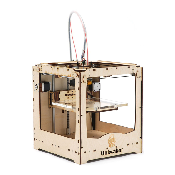
Before starting the assembly, you may want to sand the panels slightly to remove any burn marks/blemishes from the laser cutting process. You can also paint or stain your Ultimaker Original+. Be aware that paint will not cover the brown cutting edges very well. - Page 10 In this manual, you will read about FRONT side, BACK side, LEFT side, image 1: sides of the Ultimaker Original+...
-
Page 11: Assembling The Ultimaker Original
Assembling the Ultimaker Original+ ASSEMBLING THE FRAME WHAT YOU’LL NEED TO BUILD THIS SUB ASSEMBLY. Time: about 60 to 90 minutes Tools: hex key screwdriver (1,5mm) hex key wrench (2mm) 5.5mm (M3) socket wrench or pliers... - Page 12 • Blok 2: step 3 en 4 • Blok 3: step 5 en 6 In de bouwbeschrijving van Ultimaker (pagina 10-27) staan zeer belangrijke zaken met een uitroepteken aangegeven. Lees deze dus ook goed. Loop samen eerst alle pagina’s door, dan kan je het werk goed verdelen. Hieronder per stap nog een aantal tips.
- Page 13 3Dkanjers Bouwtips en Bouwinspectie Ultimaker Original + (heated bed) Step 1 (6.1.1.) Step 2 (6.1.2.) Step 1 (6.1.1.) Step 2 (6.1.2.) Step 1 (6.1.1.) Step 3 (6.1.3.) Step 2 (6.1.2.) © 2014 | 3Dkanjers...
- Page 14 3Dkanjers Bouwtips en Bouwinspectie Ultimaker Original + (heated bed) Step 4 (6.1.4.) Step 5 (6.1.5.) Step 4 (6.1.4.) Step 5 (6.1.5.) Step 5 (6.1.5.) Step 5 (6.1.5.) Step 5 (6.1.5.) Het resultaat © 2014 | 3Dkanjers...
-
Page 15: Step 1: Inserting The Ball Bearings
6.1.1. Step 1: Inserting the ball bearings The following parts are needed in this step. Letter Description Qnty. FRONT panel LEFT panel RIGHT panel BACK panel ball bearings 8mm image 2: parts needed for this step Every panel needed for this step has two corresponding holes. To place the ball bearings, perform the following actions: Get a panel. -
Page 16: Step 2: Mounting The Limit Switches
image 3: placing the ball bearings into the panel 6.1.2. Step 2: Mounting the limit switches Warning! Do not strain the tapped thread on the inside of the switch housing by putting a lot of force on the bolts. All limit switches are pre-tapped, you can fasten them directly with M3 bolts, no nuts required here! Caution! Note that all wires of limit switches need to be twisted,... - Page 17 image 4: parts needed for this step The orientation of the limit switches are engraved on the panels, except for the FRONT panel. The machine has 3 limit switches: • 1 with BLUE wires • 1with RED wires • 1 with LONG BLACK wires Step 2: Mounting the limit switches Assembling the frame...
- Page 18 To mount the BLUEwired limit switches, perform the following actions: Place the BLUE wired limit switch as shown in image 5. Attach the BLUE wired limit switch with two bolts M3x12mm. image 5: attaching the RED wired limit switches To attach the RED wired limit switch, perform the following actions: Attach the REDwired limit switch as shown in image 6.
- Page 19 image 6: attaching the BLUE wired limit switch To attach the BLACK limit switch with LONG wires, perform the following actions: Attach the BLACK limit switch with LONG wires as shown in image 7. Fine tuning the position will be described in another part of this manual.
-
Page 20: Step 3: Assembling The X And Y Motor
6.1.3. Step 3: Assembling the X and Y motor The following parts are needed in this step. Letter Description Qnty. LEFT panel BACK panel motors with long wires and rounded axles Motor spacer M3 washers short timing belts pulleys with a 5mm internal diameter bolts M3 x 25mm image 8: parts needed for this step...
Need help?
Do you have a question about the Original+ and is the answer not in the manual?
Questions and answers