Table of Contents
Advertisement
Advertisement
Table of Contents

Related Manuals for Ultimaker ORIGINAL+


Summary of Contents for Ultimaker ORIGINAL+
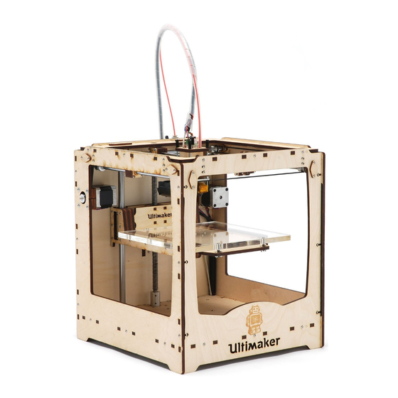
- Page 1 Ultimaker ULTIMAKER ORIGINAL+ ASSEMBLY MANUAL Original manual V3.0 2016...
- Page 2 We can not control the conditions in which you assemble the Ultimaker Original+. For this and other reasons, we do not assume responsibility and expressly disclaim liability for loss, injuries, damage, or expense arising out of or in any way connected with the assembly, handling, storage, use or disposal of the product.
-
Page 3: Table Of Contents
TABLE OF CONTENTS 1. INTRODUCTION ..................................... 5 What’s in the box? 2. FRAME ........................................13 Preparing the panels Assembling the frame Attaching various parts 3. X/Y AXLES ......................................27 Sliding blocks Attaching the caps Placing the X and Y axles 4. - Page 4 PREFACE This is the assembly manual for the Ultimaker Original+. The manual guides you through the steps to successfully assemble the 3D printer. Please read all information and follow the instructions and guidelines in this manual carefully. This ensures that possible accidents and injuries will be prevented and that you will obtain great quality prints.
-
Page 5: Introduction
(quantities, article numbers and names) that are part of the Ultimaker Original+ kit. Check if all parts are included before you start assembling. Assembling the Ultimaker Original+ takes about 8 - 16 hours and requires the following tools: hex key 2 mm (included), hex key 2.5 mm (included), a flat... -
Page 6: What's In The Box
WHAT’S IN THE BOX? LAYER 1 0,75 kg filament Power cord Serial number sticker LAYER 2 Additional pack 1144 USB cable 1225 Blue tape 1227 Hex key 2 mm 1228 Glue stick 1402 Hey key 2.5 mm 1250 SD card Bearing pack 1021 Ball bearing 8 mm... - Page 7 Cable pack 1171 Heated bed cable 1183 Double flat cable 10 wire 1185 PT100 B sensor 1513 Heater cartridge Cable management pack 1010 Velcro parts 1131 Short cable duct 1132 Long cable duct (you will only need 1) Fan pack 1326 Warning sticker 1501...
- Page 8 Grease pack 1226 Grease 1524 Copper grease Hot end pack 1048 Aluminium hot end holder 1049 Aluminium heater block 1053 Hot end isolator tube 1054 Nozzle 1055 Teflon coupler 1067 PEEK isolator 1069 Tube coupling collet 1071 Clamp clip Injection molding pack 1030 Injection molded set 1241...
- Page 9 Nuts & bolts pack 1139 Spacer 16 mm 1256 Glass retainer clip 1152 Table spring 1257 Knurled nut 1201 Washer M3 1288 Washer M6 1202 M3x10 bolt 1348 M3x4 bolt 1203 M3x12 bolt 1355 Countersunk bolt M3x8 M3x16 bolt 1204 1356 Countersunk bolt M3x20 1205...
- Page 10 Pulley pack 1084 Pulley 5 mm 1085 Pulley 8 mm UltiController pack 1129 Knob 1146 UltiPanel rev 1.1 1522 UltiController window LAYER 3 Axle pack 1011 Y linear shaft 1012 X linear shaft 1028 Z linear shaft 1046 Print head shaft X, Y 1159 Z motor with trapezoidal lead screw 1187...
- Page 11 Electronics pack 1315 Jumper (on main board) 1546 Main board 2.1.4 Motors 1017 Feeder motor 1082 X, Y motor Power adapter 1238 Power adapter...
- Page 12 LAYER 4 Laser pack 1154 Glass plate 1155 Heated bed 1294 Warning sticker 1673 Front plate 1674 Back plate 1675 Left plate 1676 Right plate 1677 Top plate 1678 Bottom plate 1679 Parts plate 1818 Aluminium base plate...
-
Page 13: Frame
FRAME In this chapter, the assembly of the frame of the Ultimaker Original+ is described. You will start preparing the panels, then you will assemble the frame and as a last step attach various parts to the frame. -
Page 14: Preparing The Panels
1. STICKERS Each Ultimaker Original+ kit has its own unique serial number. You find your Ultimaker Original+’s serial number on the box and on a sticker in the kit. Start by placing the serial number on the non-engraved side of the back panel. Fig. 1. - Page 15 2. BALL BEARINGS For this step you need the front, back, left and right panels and the 8 ball bearings (Fig. 2). Every panel has 2 corresponding holes. Take a panel, place the ball bearings on the corresponding holes and push them in. Make sure that they are inserted deep enough and do not stick out.
- Page 16 3. LIMIT SWITCHES The limit switches are used to determine the 0 point of the print head and Z stage. They make sure that the print head stays within the limits of the frame and the build plate can be calibrated. For this step you need the front, left and back panels, the limit switches and the bolts and washers (Fig.
- Page 17 Red wired limit switch To mount the red wired limit switch, perform the following actions: Take the left panel. 2. Place the red wired limit switch with the lever pointing downwards. 3. Push the limit switch towards the center of the panel as much as possible and attach with two M3x12 bolts. Fig 7. Black wired limit switch To attach the black wired limit switch, perform the following actions: Take the back panel.
- Page 18 4. BOTTOM PANEL In this step you will place the Velcro parts that will be used later to organize the electronics. You need the bottom panel and the Velcro parts. Move 4 pieces black Velcro parts through the four sets of slots of the bottom panel. Fig. 10. 2.
-
Page 19: Assembling The Frame
ASSEMBLING THE FRAME In the next steps you will put all the panels together and assemble the cube shaped frame. While assembling the frame, be careful not to put any force on the panels because they are weak in this configuration. However, when the frame is finished the structure is very strong. - Page 20 1. FIRST FOUR PANELS To assemble the frame, perform the following actions: Place the back panel on the table. Make sure the markings are facing towards you. 2. Put the top panel, with the markings downwards, into the back panel. Fig. 13. 3.
- Page 21 2. CABLE DUCTS Before adding the right and left panel you will place the cable ducts. These keep the motor and limit switch wires out of the way for safety reasons. Right side Put the frame on its left side. 2.
- Page 22 Left side Turn the frame over and put it on its right side. 2. Place the second short cable duct on the left side of the panel, fold it and tape it like you did with the cable duct on the right side.
-
Page 23: Attaching Various Parts
ATTACHING VARIOUS PARTS In the next steps you will attach the last parts to complete the frame. PARTS NEEDED Motor pack Laser pack 1082 X/Y motor Wooden part 3B Wooden part 11A Pulley pack 1084 Pulley 5 mm Nuts & bolts pack 1201 Washer M3 Belt pack... - Page 24 1. MOTORS To prepare and attach the X and Y motors, perform the following actions: Take the two 5 mm pulleys and replace the set screws in the pulleys with the new separately supplied stainless steel set screws. Fig. 28. 2.
- Page 25 5. Attach the X motor to the back panel with four M3x25 bolts and a black motor spacer. Make sure the wires face downwards. Fig. 32. 6. Attach the Y motor to the left panel with four M3x25 bolts and a black motor spacer. Make sure the wires face downwards.
- Page 26 2. OTHER PARTS Take wooden part 11A and attach it to the outside of the back panel. Use two M3x16 bolts and two lock nuts, place the lock nuts on the outside of the frame. Fig. 36. 2. Take the two wooden parts 3B (4 mm) and place them on the top panel, over the holes. 3.
-
Page 27: X/Y Axles
X/Y AXLES Once the frame is assembled, the X and Y axles can be put in the frame. Therefore you will first assemble the sliding blocks and attach the wooden caps to the frame. When this is done, the X and Y axles can be placed in the frame with pulleys, belts and sliding blocks around them. -
Page 28: Sliding Blocks
SLIDING BLOCKS PARTS NEEDED Laser pack Bearing pack Wooden parts marked FRONT (A, B, C (2x), D, E) Sintered bushing 1056 Wooden parts marked BACK (A, B, C (2x), D, E) Wooden parts marked LEFT (A, B, C (2x), D, E) Nuts &... - Page 29 1. ASSEMBLING THE SLIDING BLOCKS To assemble the four sliding blocks, perform the following actions: Sort the wooden parts marked FRONT from A through E. Make sure the text is facing the same direction. Use the part C with the hole in it. 2.
- Page 30 2. ATTACHING THE CLAWS To attach the sliding block claws, perform the following actions: Put one hex nut on each of the four M3x10 bolts. 2. Put the bolts with hex nuts through the middle hole of the 6 mm wooden part C (marked FRONT, BACK, LEFT, RIGHT) and secure with one hex nut each.
-
Page 31: Attaching The Caps
Hex nut The wooden caps have to be attached in four corners (A, B, C and D) of the Ultimaker Original+ (Fig. 51). They keep the axles in place. The wooden caps with hole will be placed on the inside, except for the places where the short motor belts pass over the bearings. - Page 32 To place the wooden caps, perform the following steps: In corner A, attach a wooden cap with hole and a wooden cap without hole to the front panel. Secure with two M3x16 bolts and two hex nuts. Fig. 52 and 53. 2.
- Page 33 5. In corner C, attach a wooden cap with hole and a wooden cap without hole to the right panel. Secure loosely with only one M3x16 bolt and one hex nut. Fig. 58. 6. Attach only a wooden cap without hole to the back panel. Secure loosely with only one M3x16 bolt and one hex nut. Fig.
-
Page 34: Placing The X And Y Axles
PLACING THE X AND Y AXLES PARTS NEEDED Axles pack Nuts & bolts pack 1011 Y linear shaft (long) 1204 M3x16 bolt 1012 X linear shaft (short) 1209 Hex nut 1211 Set screw Belt pack 1086 Long timing belt Pre-assembled parts Sliding block (front, back, left, right) Pulley pack 1088... - Page 35 First prepare all the pulleys by replacing the set screws inside the pulleys by the stainless steel set screws that are separately supplied. Do not screw them in too far, the pulleys must be able to slide over the axles. Front X axle Take one X axle (short).
- Page 36 Back X axle To correctly place the back X axle, perform the following actions: Take the other X axle (short). 2. Rotate the wooden cap without hole (right panel, back). 3. Insert the X axle through the right panel and move towards the left panel. 4.
- Page 37 Left Y axle To correctly place the left Y axle, perform the following actions: Take one Y axle (long). 2. Rotate the wooden cap without hole (back panel, left). 3. Insert the Y axle through the back panel and move towards the front panel. Fig. 73. 4.
- Page 38 Right Y axle To correctly place the right Y axle, perform the following actions: Take the other Y axle (long). 2. Rotate the wooden cap without hole (back panel, right). 3. Insert the Y axle through the back panel and move towards the front panel. 4.
-
Page 39: Z Stage
Assembly of the Z stage consists of several parts. You will start by preparing the aluminium base plate and heated bed, that together form the Z stage. After this, the Z stage cap will be assembled and the Z stage can be installed in the Ultimaker. -
Page 40: Assembling The Z Stage
ASSEMBLING THE Z STAGE PARTS NEEDED Laser pack Grease pack 1154 Glass plate 1524 Copper grease 1155 Heated bed Injection molding pack 1818 Aluminium base plate Wooden main part Z stage cap 6 mm 1243 Heated bed cable clip Wooden middle part Z stage cap 4 mm Wooden left part Z stage cap 4 mm Nuts &... - Page 41 To correctly prepare the base plate, perform the following actions: Place the aluminium plate in front of you, as shown on the pictures below. 2. Place the two linear bearings over the corresponding holes in the corners. Fig. 84. 3. Loosely secure them with four M4x10 bolts each, use the 2.5 mm hex key. Make sure that the bearings can still move a little bit, you will calibrate them later.
- Page 42 2. PREPARING THE HEATED BED Before you can place the heated bed on the base plate, you need to attach some parts. You need the heated bed, the heated bed cable, two glass retainers, four small countersunk bolts (M3x8) and four lock nuts (Fig. 88).
- Page 43 Perform the following actions: Place the two glass retainer clips on the back of the heated bed, with the wide side at the bottom (black) side. 2. Secure them with two countersunk bolts and two lock nuts each. Fig. 89. 3.
- Page 44 3. PREPARING THE BED AND BASE PLATE Now that the base plate and bed have been prepared, you can connect them to finish the Z stage. You need three long countersunk bolts (M3x20), three springs, three knurled nuts, three large washers (M6), two more glass retainer clips, the heated bed cable clip and some copper grease (Fig.
- Page 45 Perform the following actions: Take the M6 washers and apply some copper grease on the round side. Fig. 93. 2. Place the washers over the knurled nuts with the grease upwards. Fig. 94. 3. Put the knurled nuts through the three holes of the base plate, in the front, right and back middle. Fig. 95. 4.
- Page 46 5. On the front two springs, place a glass retainer clip. Fig. 97. 6. Put the heated bed on top of the springs and secure with the three countersunk M3x20 bolts. Fig. 98 and 99. Tighten the bolt and knurled nut in the back until there is approximately 1 mm of space between the bed’s screw terminal and the aluminium base plate.
- Page 47 4. Z STAGE CAP The Z stage cap will be placed over the back of the Z stage, to cover the bearings. You need the wooden parts, ten hex nuts, six M3x12 bolts and 4 M3x14 bolts (Fig. 103).
- Page 48 4. Place six hex nuts in the slots at the sides and attach the wooden left and right parts with six M3x12 bolts. Fig. 106 and 107. Make sure the part with the extra tab at the top is placed on the left side (towards the U of Ultimaker). This tab will activate the Z limit switch.
-
Page 49: Installing The Z Stage
INSTALLING THE Z STAGE PARTS NEEDED Axles pack Nuts & bolts pack 1028 Glass plate 1202 M3x10 bolt 1159 Heated bed 1203 M3x12 bolt 1204 M3x16 bolt 1209 Hex nut Laser pack Wooden part 3A Pre-assembled parts Z stage Grease pack 1126 Grease Z stage cap... - Page 50 1. PLACING THE Z STAGE INSIDE THE FRAME To install all the Z stage parts in the machine, perform the following actions: Place the frame on its back, with the bottom panel facing you. 2. Insert the two Z linear shafts through the holes in the bottom panel, until they are about halfway. Fig. 109. 3.
- Page 51 5. Place the wooden parts 3A over the end of the Z linear shafts and secure with two M3x16 bolts and two hex nuts each. Insert the bolts from the inside of the frame. Fig. 115 and 116. 6. Insert the lead screw of the Z motor through the hole in the middle and screw into the trapezoidal lead nut of the Z stage.
- Page 52 2. APPLYING GREASE For the lead screw, a small packet of green grease is supplied. This grease makes sure that the Z motor’s lead screw can rotate smoothly. Set the frame upright again and make sure the Z stage is all the way at the top. 2.
- Page 53 3. CALIBRATING To ensure that the Z stage moves smoothly and accurately, you now need to calibrate the square flanged bearings. Move the Z stage cap all the way up and tape it to the top panel to keep it out of the way. Fig. 122. 2.
-
Page 54: Print Head
PRINT HEAD The print head exists of several parts that must be assembled: the housing, hot end and fan. When the print head is assembled it can be placed in the frame and can be aligned. -
Page 55: Print Head Assembly
PRINT HEAD ASSEMBLY PARTS NEEDED Hot end pack Injection molding pack 1048 Aluminium hot end holder 1037 Print head coupling plate 1049 Aluminium heater block 1053 Hot end isolator tube Laser pack 1054 Nozzle Wooden part FRONT 1055 Teflon coupler Wooden part BACK 1067 PEEK isolator... - Page 56 1. WOODEN PARTS First prepare the wooden parts of the print head housing. You will need the following parts (Fig. 127): Take the wooden part marked TOP and attach the black injection molded part with one M3x12 bolt and a hex nut. Put this part aside, you will need it later on.
- Page 57 2. Take the wooden print head housing parts marked FRONT, BACK, LEFT, RIGHT. 3. Place one linear bearing in the FRONT and the BACK side of the print head housing. Make sure the engravings are on the outside. Fig. 130 and 131. Look at the inside of the linear bearings and note their orientation.
- Page 58 2. HOT END Now prepare the hot end. Take the aluminium heater block and hold it with the big hole up. Attach the nozzle into the bottom of the heater block. Make sure it is as tight as possible (by hand). Fig. 136. 2.
- Page 59 3. CABLES To connect the hot end cables, perform the following actions: Guide the PT100 and the heater cartridge through the front left hole of the aluminium hot end holder (with the hot end being in the front right hole) and the print head housing. Fig. 140, 141, 142 and 143. It is easiest to guide the PT100 from the top and the heater cartridge from the bottom of the print head housing and aluminium hot end holder.
- Page 60 2. Place the PT100 and heater cartridge in the side of the aluminium heater block with the three holes. The heater cartridge goes in the biggest hole and PT100 in the middle hole. Fig. 144 and 145. 3. Secure the PT100 and heater cartridge with one M3x10 bolt. Fig. 146. 4.
- Page 61 4. TIGHTENING UP Place the wooden part TOP on the rest of the assembly, with the injection molded part on the right side. Fig. 149. 2. Tighten the four M3x10 bolts of the print head housing. Fig. 150. 3. Place the teflon coupler into the wooden part 8B and the peek isolator. Fig. 151 and 152. 4.
- Page 62 5. FAN ASSEMBLY First place the warning sticker on the metal fanduct. Fig. 155. 2. Place the metal fanduct around the heater block, make sure the fan will be on the left side of the print head. Fig. 156. 3. Use two M3x4 bolts to lock it into place by screwing them into the aluminium plate of the hot end assembly. Fig. 157. 4.
-
Page 63: Placing The Print Head In The Frame
PLACING THE PRINT HEAD IN THE FRAME PARTS NEEDED Axles pack Pre-assembled parts 1046 Print head shaft X, Y Wooden part C Print head Nuts & bolts pack M3x30 bolt 1208 1209 Hex nut... - Page 64 To place the print head in the frame, perform the following actions: Guide the X print head shaft through the print head, from left to right. Fig. 162. 2. Place the print head with the X shaft inside the frame, mind the orientation. Fig. 163. 3.
- Page 65 6. Now guide the Y print head shaft through the print head, from front to back. Fig. 168. Tilt the front and back sliding blocks and insert the Y shaft into the sliding blocks. 8. Close the claws of the front and back sliding blocks. Now place the wooden parts C to secure the Y print head shaft.
-
Page 66: Aligning The Print Head
ALIGNING THE PRINT HEAD After placing the print head into the frame, you have to make sure that the print head shafts are exactly 90º. To correctly align the shafts, perform the actions described below. PARTS NEEDED Laser pack Calibration stick 1. - Page 67 2. X AXLES Position the pulleys on the X axles so that the long left and right timing belts are positioned in a straight line above the Y axles. Fig. 178. 2. Place the two calibration sticks on each side of the back X axle. Fig. 179. 3.
- Page 68 3. Y AXLES Position the pulleys on the Y axles so that the long front and back timing belts are positioned in a straight line above the X axles. 2. Place the two calibration sticks on each side of the right Y axle. Fig. 182. 3.
-
Page 69: Feeder
The feeder consists of three parts that must be assembled before the feeder can be placed on the Ultimaker: the main feeder housing, clamp and drive bolt. Once the feeder is placed on the Ultimaker, the bowden tube and spool holder will be connected as well. -
Page 70: Assembling The Feeder
ASSEMBLING THE FEEDER PARTS NEEDED Injection molding pack Bearing pack Small black gear 1021 Ball bearing 8 mm Black wheel Small ball bearing 1142 Side plate A Feeder pack Side plate B Mounting plate Feeder quick fit coupling 1016 U-bracket 1133 Knurled wheel Bolt clip... - Page 71 1. MAIN FEEDER HOUSING For the assembly of the feeder housing you will need the following parts (Fig. 186).
- Page 72 To assemble the main feeder housing, perform the following steps: Put the small black gear onto the motor axle, note the D shape of both. Make sure the top of the gear is flush with the axle. Fig. 187 and 188. Use a redundant piece of wood to place the gear, this might take some force.
- Page 73 4. Put the quick fit coupling into the T-slot, note the orientation. Fig. 191. 5. Place wooden parts 10C and 10D on top and loosely secure the wooden parts to the motor with two M3x25 bolts (through part 10D) and two M3x20 bolts (through part 10C). The motor’s position will be adjusted later. Fig. 192, 193 and 194.
- Page 74 2. CLAMP ASSEMBLY For the assembly of the feeder clamp you will need the injection molding parts, small ball bearing, feeder spring, washer and nuts and bolts (Fig. 197).
- Page 75 To assemble the feeder clamp, perform the following steps: Place the small ball bearing into the hole in the black wheel. Fig. 198. Use a redundant piece of wood to fit the bearing in place. 2. Insert four M3x16 bolts through the flat side of side plate A. Fig. 199. 3.
- Page 76 5. Put the black wheel in the notch in the mounting plate. Insert one M3x20 bolt through the side plates and ball bearing and place one lock nut on the end of the bolt. Fig. 204 and 205. 6. Put the U-bracket onto the clamp assembly. Take one M3x25 bolt and put a washer and the spring around it. Insert the bolt through the hole in the U-bracket and tighten.
- Page 77 3. DRIVE BOLT ASSEMBLY For the drive bolt assembly you will need the pre-assembled feeder, wooden gear, wooden gear cap, knurled wheel, bolt clip, M6 nut, M6 washers, M6 cap nut, bolts and lock nuts (Fig. 210).
- Page 78 To assemble the drive bolt, perform the following steps: Take the wooden gear and place the M8 hex nut into the corresponding hole. Make sure it is as straight as possible; if the nut is slanted, this might lead to feeder problems later on. Fig. 211. 2.
- Page 79 5. Place two M8 washers over the knurled wheel. Ensure the flat sides of the washers are facing each other. Fig. 217. 6. Put the drive bolt assembly through the two ball bearings and check if the notch in the knurled wheel is aligned with the ball bearing.
-
Page 80: Bowden Tube
BOWDEN TUBE PARTS NEEDED Bowden pack Feeder pack & hot end pack 1097 Bowden tube 1071 Clamp clip 1266 Spiral sleeve The bowden tube has one end marked with blue tape. This end has been slightly drilled out to make the inserting of material easier. - Page 81 3. Place the other side of the bowden tube into the tube coupling collet on the print head. Push it through the print head housing, into the teflon coupler. Fig. 226 and 228. Insert the screwdriver through the back of the print head housing to guide the bowden tube in place. 4.
-
Page 82: Spool Holder
SPOOL HOLDER PARTS NEEDED Laser pack Wooden parts 11B (short) Wooden parts 11B (long) Wooden parts 11C... - Page 83 The laser pack contains two different spool holders. The small spool holder can hold exactly one spool of Ultimaker filament. The larger spool holder can hold exactly two spools of Ultimaker filament. Take the two short wooden parts 11B and place two wooden parts 11C in the corresponding slots. Fig. 233.
-
Page 84: Ulticontroller
ULTICONTROLLER The UltiController is the display and control panel of your Ultimaker Original+. This chapter describes how to assemble it and place it on the front panel. - Page 85 PARTS NEEDED Laser pack Cable pack UltiController front 1171 Double flat cable 10 wire UltiController back Nuts & bolts pack UltiController left UltiController right 1139 Spacer 16 mm 1540 Nylon hex nut UltiController pack 1541 Nylon bolt M3x12 1129 Knob 1542 Nylon bolt M3x25 1146...
- Page 86 To assemble the UltiController, perform the following actions: Remove the foil from the display and the window. 2. Place the wooden part front face down and fit the UltiController window in the cutout. Fig. 237. 3. Insert four nylon M3x25 bolts through the wooden part front, put four 16 mm spacers over them and place the UltiPanel on top.
- Page 87 5. Plug the flat cables into the connectors and mark the other end of the cable connected to EXP1. Fig. 243. 6. Put the flat cables through the wooden part back and attach the back to the front with two nylon bolts M3x12 and two nylon hex nuts.
-
Page 88: Electronics
ELECTRONICS The last step of the assembly process is connecting the electronics. You will first mount the main board to the bottom side of the Ultimaker Original+ and then connect all the wires to it. -
Page 89: Mounting The Main Board
MOUNTING THE MAIN BOARD PARTS NEEDED Electronics pack Nuts & bolts pack 1315 Jumper (on main board) 1206 M3x20 bolt 1546 Main board 2.1.4 1502 Spacer 8 mm... - Page 90 Touch bare metal before continuing with the following steps. Place the Ultimaker on its left side and raise the Z stage. 2. Insert four M3x20 bolts through the bottom panel from the inside and place the spacers around the bolts. Fig. 250 and 251.
-
Page 91: Connecting
CONNECTING In the following steps you will connect all the cables to the appropriate places on the main board. On the bottom panel is engraved where all cables should be connected. 1. HEATERS Take the white heater cartridge wires. Use a small flat screwdriver to press on the terminal marked Heater 1 and insert the heaters. - Page 92 3. Take the plug from the Z motor and connect it to Z-motor. Fig. 258. 4. Take the plug from the feeder motor. This is the shortest motor cable coming from the top right corner. Connect it to E1-motor. Fig. 259. 5.
- Page 93 3. ULTICONTROLLER Take the flat cables from the UltiController. You have marked one of the cables while assembling the controller. 2. Connect the marked cable to exp. 1, connect the other to exp. 2. Fig. 261. 4. SENSORS Connect the PT100 sensor to temp 1. Fig. 262. 2.
- Page 94 5. LIMIT SWITCHES Take the blue wired limit switch from the bottom left corner and connect it to x-end stop. Fig. 264. 2. Take the red wired limit switch from the bottom left corner and connect it to y-end stop. Fig. 265. 3.
- Page 95 Lastly, push the main board towards the right panel as far as possible and completely tighten the four bolts to secure the main board in place. Fig. 268. Your electronics should now look like this:...
-
Page 96: Cover
COVER PARTS NEEDED Laser pack Nuts & bolts pack Electronics cover 1206 M3x20 bolt 1502 Spacer 8 mm... - Page 97 Now that all the cables have been connected, you will place a cover over the electronics to protect the main board. Take the four M3x20 bolts and put a spacer 8 mm over each bolt. Fig. 271. 2. Screw the four bolts into the main board’s threaded spacers, but only two turns. Fig. 272. 3.
- Page 98 Congratulations! You have completed the assembly of the Ultimaker Original+. Before you can start printing you must configure and calibrate your Ultimaker Original+. Therefore, follow the steps described on website.
- Page 99 www.ultimaker.com...
Need help?
Do you have a question about the ORIGINAL+ and is the answer not in the manual?
Questions and answers