Table of Contents
Advertisement
Quick Links
Contents
Safety ············································································································ 1
Safety information ·············································································································································· 1
General operating safety ···························································································································· 1
Electrical safety ·········································································································································· 1
Safety precautions ············································································································································· 1
ESD prevention ·················································································································································· 1
Preventing electrostatic discharge ············································································································· 1
Grounding methods to prevent electrostatic discharge ·············································································· 2
Overview of the BX720E switch module ························································ 1
Product overview················································································································································ 1
High availability ·················································································································································· 1
Redundancy of devices ······························································································································ 1
Redundancy of links ··································································································································· 2
Specifications ····················································································································································· 2
Port····································································································································································· 3
Port numbering rules ·································································································································· 3
External ports ············································································································································· 3
Internal Ports ·············································································································································· 5
LEDs ·································································································································································· 5
Logical structure ················································································································································· 7
Installation guidelines ········································································································································· 8
Internal Networking ························································································ 1
Hardware compatibility ·················································································· 1
Compatibility between switch modules and Mezz NICs ····················································································· 1
Compatibility between switch modules and optical modules/cables ·································································· 1
Replacing the switch module ········································································· 1
Scenario ····························································································································································· 1
Installation tools ················································································································································· 1
Preparations ······················································································································································· 2
Replacement procedure ····································································································································· 2
Powering on and powering off ······································································· 1
Powering on the switch module ························································································································· 1
Supported power-on modes ······················································································································· 1
Operation methods ····································································································································· 1
Powering off the switch module ························································································································· 3
Supported power-off modes ······················································································································· 3
Operation methods ····································································································································· 4
Configuring the switch module ······································································· 1
Logging in to the switch module ························································································································· 1
Obtaining the related data ·························································································································· 1
Login mode ················································································································································ 1
Logging in to the switch module through the SYS serial port (console port) ·············································· 1
Logging in to the SOL serial port through redirection················································································· 2
Configuring the management IP address of the switch module ········································································· 3
Obtaining and planning related data ·········································································································· 3
Configuration mode ···································································································································· 3
Configuring the management IP address through Web UI of the OM module ··········································· 3
Configuring the management IP address through the CLI of the OM module ··········································· 5
Configuring the management IP address through the CLI of the switch module ······································· 5
Configuring services of the switch module ········································································································· 5
Saving the configuration in profile ······················································································································ 6
i
Advertisement
Table of Contents

Related Manuals for H3C BX720E


Summary of Contents for H3C BX720E
-
Page 1: Table Of Contents
Safety precautions ············································································································································· 1 ESD prevention ·················································································································································· 1 Preventing electrostatic discharge ············································································································· 1 Grounding methods to prevent electrostatic discharge ·············································································· 2 Overview of the BX720E switch module ························································ 1 Product overview················································································································································ 1 High availability ·················································································································································· 1 Redundancy of devices ······························································································································ 1 Redundancy of links ···································································································································... - Page 2 Common operations ··········································································································································· 7 Logging in to the Web UI of the OM module ······························································································ 7 Logging in to the CLI of the OM module ···································································································· 8 Firmware upgrade·························································································· 1...
-
Page 3: Safety
General operating safety • Only H3C authorized or professional engineers are allowed to operate the device. • Keep the device clean and dust-free. Do not place it in a humid place or allow liquids to enter it. -
Page 4: Grounding Methods To Prevent Electrostatic Discharge
Grounding methods to prevent electrostatic discharge When removing or installing the device, you can use one or multiple of the following grounding methods to prevent electrostatic discharge: • Wear an ESD wrist strap and ensure that it is reliably grounded. Ensure that the ESD wrist strap makes good skin contact and can be flexibly stretched out and draw back. -
Page 5: Overview Of The Bx720E Switch Module
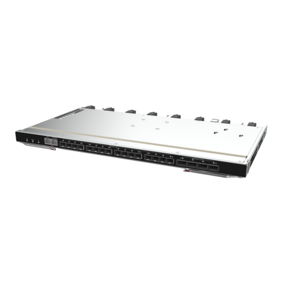
As an Ethernet switching control module inside the blade enclosure, the H3C UniServer BX720E switch module (BX720E for short) provides data switching functions for servers installed in the front slots of the blade enclosure and centrally provides external data ports, to achieve the communication between blade servers and external networks. -
Page 6: Redundancy Of Links
Figure 2 Installation position for switch modules (1) ICM1 slot (2) ICM2 slot (3) ICM3 slot (4) ICM4 slot (5) ICM5 slot (6) ICM6 slot Redundancy of links Switch modules are connected to blade servers through the mid plane and provide external ports to achieve uplink connection for blade servers. -
Page 7: Port
Category Item Description • Operating temperature: 5°C to 45°C (41°F to 113°F) Temperature • Storage temperature: –40°C to 70°C (–40°F to 158°F) • Operating humidity: 8% to 90% (non-condensing) Humidity • Environment Storage humidity: 5% to 95% (non-condensing) specifications • Operating altitude: –60 to +5000 m (–196.85 to +16404.20 ft) (The allowed maximum temperature decreases by 0.33°C(32.59°F) as the altitude increases by 100 m (328.08 ft) from 900 m (2952.76... - Page 8 Figure 3 External ports (1) AMC serial port (2) SYS serial port (Console port) (3) 10GE optical port (4) 40GE optical port Table 2 Description of external ports Port Port name Port type Description quantity Serial port used to enter the AMC CLI. The baud rate is 115200 bit/s.
-
Page 9: Internal Ports
Internal Ports Table 3 shows the internal port provided by the switch module. Table 3 Description of the internal port Port Port Port quantity Description name type • A total of 32 ports are provided to connect to blade servers. Port numbers are XGE 1/0/1 through XGE 1/0/32. - Page 10 Figure 4 LEDs (1) UID LED (2) RUN LED (3) Health LED (4) Port LED The appearance of all port LEDs of the switch module is identical. The figure takes one port LED for illustration. Table 4 Description of LEDs Name Color Status...
-
Page 11: Logical Structure
Name Color Status reen as follows: • 10GE optical port Steady green: The port link is connected, the port rate is 10 Gbit/s, but no data is transmitted. Flashing green: The port link is connected, the port rate is 10 Gbit/s, and data transmission is in progress. -
Page 12: Installation Guidelines
Installation guidelines • As shown in Figure 6, up to six switch modules can be installed in the blade enclosure. • The installation positions of the switch modules and Mezz NICs must satisfy internal connection relationships. For details, see Table 5Figure 7 Table 5Figure •... -
Page 13: Internal Networking
Table 5 Connections between switch modules and Mezz NICs Maximum number of Model of Blade server Internal connection diagram supported Mezz NICs H3C UniServer B5700 G3 Figure 7 Note H3C UniServer B7800 G3 Figure 8 The connection diagram is a logical diagram used to identify the mapping between Mezz NIC slot and switch module slot. - Page 14 Figure 8 shows the second mode of connections between switch modules and Mezz NICs, where: • The onboard NIC is connected to the active and standby OM modules. • Mezz NIC 1 and Mezz NIC 4 are connected to switch modules in slot 1 and slot 4. •...
-
Page 15: Hardware Compatibility
Compatibility between switch modules and Mezz NICs Table 6 describes the compatibility between the BX720E switch module and the Mezz network adapter. Table 6 Mezz NIC compatible with the switch module Mezz NIC model... - Page 16 • 150 m (492.13 16G/8G/4G FC optical ft) (8G) SFP-FC-16G-SW-MM850-CM 850 nm module • 380 m (1246.72 ft) (4G) 16G/8G/4G FC optical SFP-FC-16G-LW-SM1310-CM 1310 nm 10 km (6.21 miles) module Note • H3C SFP/SFP+ modules are recommended as switch modules.
- Page 17 • For specifications of optical modules or cables, see the H3C Optical Module Manual. • The types of H3C SFP/SFP+ modules may change over time. If you need accurate information about module types, consult H3C marketing or technical support personnel.
-
Page 18: Replacing The Switch Module
Replacing the switch module Scenario • The switch module is faulty. • The switch module needs to be replaced by a switch module or straight-through module in another model. Installation tools The following tools or devices may be required when you install, use, and maintain the equipment. Table 9 Required tools Image Name... -
Page 19: Preparations
." Replacement procedure NOTE: For specific procedures, see http://www.h3c.com/cn/home/qr/default.htm?id=354. Remove the switch module. Press the unlock button on the switch module to fully open the ejector, and slowly pull the switch module out of the chassis horizontally. Put the switch module into the ESD bag. - Page 20 Install the switch module. Take out the switch module to be installed from the ESD bag. Press the unlock button to automatically open the ejector. Slowly insert the switch module into the blade enclosure horizontally with UP facing upwards, and then lock the ejector.
-
Page 21: Powering On And Powering Off
Powering on and powering off This section describes how to power on/off the switch module. Powering on the switch module This section describes how to power on the switch module. Supported power-on modes Table 10 describes power-on modes supported by the switch module. Table 10 Power-on modes supported by the switch module Power-on mode Application scenario... - Page 22 As shown in ① of Figure 9, open the browser on the PC and enter the URL (in the format of https://OM_ip_address) used to log in to the OM web UI. As shown in ②, enter the admin user name and password. As shown in ③, click Login. Figure 9 Logging in to the web UI of the OM module As shown in Figure...
-
Page 23: Powering Off The Switch Module
After login, the OM CLI displays the login page, as shown below. ****************************************************************************** * Copyright (c) 2004-2019 New H3C Technologies Co., Ltd. All rights reserved.* * Without the owner's prior written consent, * no decompiling or reverse-engineering shall be allowed. -
Page 24: Operation Methods
Table 13 Power-off modes supported by the switch module Power-off Mode Application Scenario Mode 1: The switch module is powered off together with the blade enclosure. Mode 2: The switch module is powered off through the OM web UI. The blade enclosure and switch module are powered on, the switch module works properly. - Page 25 Figure 12 Logging in to the web UI of the OM module As shown in Figure 13, perform the following steps to power off the switch module. a. Click Switch Module. b. Select a target switch module. c. Click Power state, and click Power Off. d.
- Page 26 After login, the OM CLI displays the login page, as shown below. ****************************************************************************** * Copyright (c) 2004-2019 New H3C Technologies Co., Ltd. All rights reserved.* * Without the owner's prior written consent, * no decompiling or reverse-engineering shall be allowed.
-
Page 27: Configuring The Switch Module
Configuring the switch module Note The data in operations of this section is used for illustration only. The actual operation data on site shall prevail. Logging in to the switch module Obtaining the related data Before logging in to the switch module, obtain the related data, as described in Table Table 16 Related data Required Data... -
Page 28: Logging In To The Sol Serial Port Through Redirection
After login, the CLI of the switch module displays the login page, as shown below. ******************************************************************************** * Copyright (c) 2004-2019 New H3C Technologies Co., Ltd. All rights reserved. * Without the owner's prior written consent, * no decompiling or reverse-engineering shall be allowed. -
Page 29: Configuring The Management Ip Address Of The Switch Module
Configuring the management IP address of the switch module Obtaining and planning related data Before configuring the management IP address of the switch module, obtain and plan the related data, as described in Table Table 18 Related data Data Example Required data •... - Page 30 Configuration procedure As shown in Figure 15, click Enclosure – Chassis and choose Enclosure > Network > IPv4 Setting. Figure 15 Configure the management IP address (1) Toggle on the Enable in Position button to enable the function of configuring the management IPv4 address of the ICM module, and configure the management IP address of the ICM module, as shown in Figure...
-
Page 31: Configuring The Management Ip Address Through The Cli Of The Om Module
• You have logged in to the switch module. For details, see "Logging in to the switch module." Configuration procedure For specific operation procedures, see the H3C UniServer BX720E Switch Module Configuration Command Manual. Configuring services of the switch module Prerequisites •... -
Page 32: Saving The Configuration In Profile
Configuration procedure For specific operation procedures, see the H3C UniServer BX720E Switch Module Configuration Command Manual. Saving the configuration in profile Prerequisites • The switch module has been powered on. For details, see "Powering on the switch module." • You have logged in to the switch module. For details, see "Logging in to the switch module."... -
Page 33: Common Operations
<Sysname>tftp 192.168.1.1 put flash:/uis-cmw710-boot-1.00.10.bin Press CTRL+C to abort. Total Received % Xferd Average Speed Time Time Time Current Dload Upload Total Spent Left Speed 100 5572k 0 100 5572k 832k 0:00:06 0:00:06 --:--:-- 828k <Sysname> In the user view on the CLI of the switch module, run the command to back up profile tftp put startup.cfg on the TFTP file server:... -
Page 34: Logging In To The Cli Of The Om Module
① of As shown in Figure 19, open the browser on the PC and enter the URL (in the format of ②, enter the https://OM_ip_address) used to log in to the OM web UI. As shown in ③, click name and password. As shown in Login. - Page 35 After login, the OM CLI displays the login page, as shown below. ****************************************************************************** * Copyright (c) 2004-2019 New H3C Technologies Co., Ltd. All rights reserved.* * Without the owner's prior written consent, * no decompiling or reverse-engineering shall be allowed.
-
Page 36: Firmware Upgrade
Firmware upgrade For specific procedures, see the H3C UniServer B16000 Blade Server Upgrade Guide.
Need help?
Do you have a question about the BX720E and is the answer not in the manual?
Questions and answers