Bacharach MGS-550 - Dual Sensor Gas Detector Quick Start Guide
- User manual (79 pages) ,
- Installation manual (12 pages) ,
- Quick start manual (2 pages)
Advertisement
Introduction
The MGS-550 gas detector is designed for use in refrigeration applications and may be used as a standalone device, connected to the MGS-402 or MGS-408 controllers, or connected to a facility's BMS / BAS. It enables compliance with refrigeration safety codes (ASHRAE 15, EN 378, CSA-B52) and features audible and visual alarms to alert personnel in the event of a leak.
Safety Instructions

The MGS-550 is NOT certified or approved for operation in oxygen-enriched atmospheres. Failure to comply may result in severe injury or death.

Use this product ONLY for the purposes and under the conditions listed in MGS-550 User Manual. Failure to comply may result in injury and / or damage to the product.
The MGS-550 has not been designed to be intrinsically safe for use in areas classified as being hazardous locations. For your safety, DO NOT use in hazardous locations.
Consult a qualified professional before connecting the MGS-550 to devices not mentioned in this manual. Failure to comply may result in injury and / or damage to the product.

Except for the maintenance detailed in this manual, this product should ONLY be opened and / or serviced by authorized personnel. Failure to comply may void the warranty.

Comply with a l local and national laws, rules and regulations associated with this equipment. Operators should be aware of the regulations and standards in their industry / locality for the operation of the MGS-550.
The MGS-550 must be insta led by a suitably qualified technician who wi l insta l this unit in accordance with these instructions and the standards in their particular industry / country. This document is only intended as a guide and the manufacturer bears no responsibility for the insta lation or operation of this unit.
Component Overview

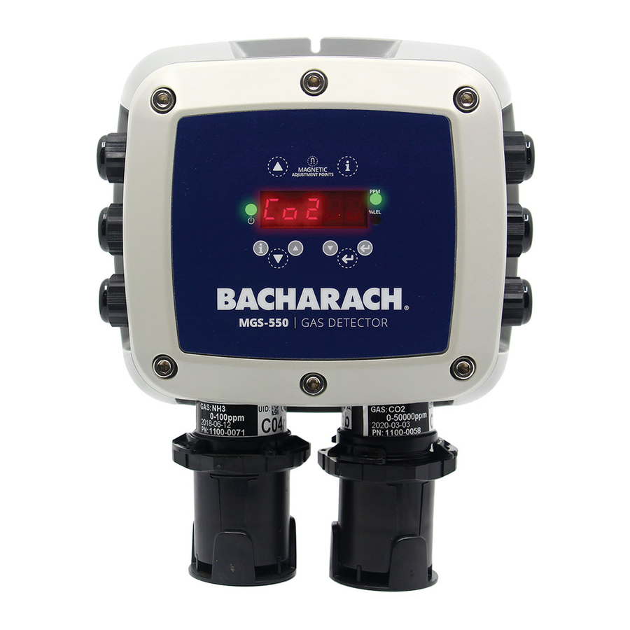
Front Panel
Front Panel Component Description:
- Controller Power LED
- Concentration LEDs (PPM, %LEL, %Vol - both off)
- 5-digit, 7-segment display (Gas, real-time concentration)
- Magnetic Switches (dashed line around icon)
- Tactile Switches (solid line around icon)
- Local gas sensor element (remote sensor elements available)
Internal Connections

Installation
The manufacturer of this product recommends that a bump test be performed following installation to verify instrument functionality.
STEP 1 Mount Gas Detector & Remove Lid
DO NOT allow the lid/sensor to hang from the ribbon cable. Failure to comply may result in damage to the product.
- Mount the MGS-550 according to the product dimensions, maximum wiring lengths and following considerations:
- Environment: the full range of environmental conditions when selecting a location.
- Application: the specifics of the application (possible leaks, air movement / draft, etc.), when selecting a location.
- Accessibility: the degree of accessibility required for maintenance purposes when selecting a location.
- Target Gas: the specific gravity of the target gas when selecting the height of the instrument.
- Using a 5/32' (4 mm)hex key / Allen wrench (not included)remove the lid and disconnect the ribbon cable from the base.
- Set the lid and rubber gasket aside to be reinstalled later
STEP 2 Wire Connections
Ensure that all wiring connections are made BEFORE applying power.
POLARITY: For 24 VAC installations in a daisy-chain configuration, the neutral polarity must be maintained for all instruments.
The MGS-550 must be powered by either (a) a suitable UL 60950 / CSA certified power supply that is isolated from line voltage by double insulation, or (b) an appropriately rated UL listed / CSA Class 2 transformer.
Refer to MGS-550 User Manual for instructions for connecting to the MGS-402 or MGS-408 controller.
- Strip 0.2 to 0.25 inches(5 to 7 mm) of wiring insulation.
- Unscrew the appropriate cable gland and gasket.
- Connect the wires as indicated in the Internal Connections in Section 3. Component Overview. (Refer to the MGS-550 User Manual for complete wiring details.)
- Connect the shield of the power wires to the earth ground of the central control system.
- Screw the gland gasket onto the housing and tighten.
STEP 3 Installing One or Two Sensors
The MGS-550 will come with one or no sensors installed from the factory.
The gas detector may have come with one factory installed gas sensor element. A second gas sensor element may be installed (if applicable)in the second M25 Cable gland at the bottom of the gas detector.
Any newly installed sensor(s) will need to be registered with the gas detector.
- Remove the factory installed cable gland and gasket.
- Route the sensor lead into the cable gland with gasket installed and tighten sensor into the gas detector housing.
- Plug the sensor lead into either sensor connector J2 or J3 (see component overview, Internal Wiring Description) routing the sensor as shown in the diagram below. If both sensors are to be installed (none installed from the factory) follow the above instructions for each sensor to be installed.
STEP 4 Reconnect Lid
DO NOT leave excess cable inside of the gas detector housing. Failure to comply may result in damage to the product.
When installing the sensor ribbon cable, care must be taken to ensure the proper orientation of the connector at both ends of the cable. Failure to ensure proper orientation may result in loss of functionality and / or product damage.
To achieve proper seal, the lid screws should be torqued to 15 to 20 lbfin (1.5 to 2.0 Nm).
- Ensure that all excess wire is minimized in the enclosure so it doesn't interfere with internal components.
- Reinstall the rubber gasket. Ensure that it is correctly seated by placing the side with two grooves face down and the edge with two bumps on the top.

- Carefully reattach the ribbon cable to J1 as shown in Internal Wiring Description in Section 2, carefully noting the keyed position on the connector.
![]()
- Using a 5/32' (4 mm)hex key / allen wrench, tighten the lid screws in an "X" tightening pattern.


STEP 5 | Register the New Sensor
If there was a sensor element installed in Step 3, the sensor needs to be registered with the gas detector.
- Power up the gas detector. The detector will prompt you to start the registration. (e.g., "rEg 2").
- Acknowledge by tapping [↵]. The detector will indicate a successful registration (e.g., "PASS2") if the sensor was correctly installed.
Operation Overview
Refer to MGS-550 User Manual for complete configuration and operation instructions.
Both tactile (Press or Hold) and magnetic (Tap or Hold) switches are provided depending on the users method of interface. Both sets of switches have redundant functions and can be used to configure, calibrate and maintain the MGS-550.
The following table describes the switches functionality
| Button / Mag Switch | Description |
 | Hold: 3sec - Access User Menu Hold: 3sec - Returns to next higher menu without saving changes (ESC) Press / Tap: Brings up sensor ID in succession |
 | Press / Tap: Scrolls through User Menu in sequence Hold: Accelerates scrolling Hold Up Arrow at Top of Menu: Enters Diagnostic Screen |
 | Press / Tap: Confirms menu selection Press / Tap During Alarm: Mutes buzzer Hold: Cancels Off-Line Mode Hold: Acknowledge latched alarm / fault |
LED indicators
| STATE | LEDs | Display | Relay 11 | Relay 21 | Relay 31 | Buzzer |
| Warm-Up | Flashing Green, 0.5 Hz | Display is blank | Off-line | Off-line | Off-line | OFF |
| Normal | Constant Green | Toggles between target gas name and real-time concentration for each sensor installed | Normal | Normal | Normal | OFF |
| Low Alarm (Sensor 1 and / or Sensor 2) | Flashing Red, 0.5 Hz | Display will toggle between ALARM, gas name, concentration of each sensor until concentration falls below low alarm level | Alarm State | Normal | Normal | PULSE, 0.5 Hz |
| High Alarm (Sensor 1 and / or Sensor 2) | Flashing Red, 2 Hz | Display will toggle between ALARM, gas name, concentration of each sensor until alarm is acknowledged and concentration falls below High alarm level | Alarm State | Alarm State | Normal | PULSE, 2 Hz |
| Fault Alarm (Sensor 1 and / or Sensor 2) | Constant Amber | Display will toggle between FAULT 1 (or 2), gas name, concentration of each sensor until the fault is corrected and acknowledged | Normal | Normal | Fault State | CONSTANT |
| Off-line | Green > Amber > Red | "oFFLn" is displayed | Off-line | Off-line | Off-line | OFF |
1 - Each of the three relays can be configured for low alarm, medium alarm, high alarm or fault – this example of operation assumes a low alarm, high alarm and fault configuration
General Calibration Procedure
The MGS-550 MUST NOT be in an alarm or fault condition during calibration. Acknowledge any alarms or faults BEFORE attempting to begin the calibration process.
Except for CO2or O2 sensors, calibration gas must be in a balance of air, not nitrogen (N2).
Calibration and / or bump testing requires the MGS-550 calibration adapter kit (P/N: 1100-0034).
- Ensure the instrument has been powered on for at least 1 hour prior to beginning the sensor adjustment procedure. For semiconductor sensors, you must wait at least 24 hours.
- Assemble the calibration kit.
- Firmly push the calibration adapter over the calibration port on the sensor assembly.
- If using a variable flow regulator, adjust the gas flow to approximately 0.3 L/min.

Zero Adjustment
Except for CO2or O2 sensors, ambient air may be used instead of zero gas if the area is know to be free of the target gas or any gases to which the sensor may be cross-sensitive.
- Enter the menu and select function F-02 Zero Sensor:
- Press the [UP]/[DOWN] arrows to select the sensor to be calibrated, then press [
![]() ].
].
- Press the [UP]/[DOWN] arrows to select the sensor to be calibrated, then press [
- Apply Synthetic air (i.e., 20.9% zero air) or nitrogen, and then press [
![]() ].
]. - The current value will be blinking in the display (e.g., "2"). The gas value may go negative. This is normal.
- Wait for the current gas concentration value to stabilize.
- Press [
![]() ]to save the current calibration.
]to save the current calibration. - The instrument will indicate success status with a "PASS" display. If a "FAIL" message is displayed.
- Turn off gas flow and remove the calibration adapter from the sensor or disconnect the tubing.
- For oxygen, ensure that the concentration is below the enrichment alarm thresholds. Refer to user manual (P/N 1100-1000) for troubleshooting.
- Press [
![]() ] to exit the function
] to exit the function
 ].
].Span Adjustment
- Enter the menu and select function F-03 Zero Sensor:
- Press the [UP]/[DOWN] arrows to select the sensor to be calibrated, then press [
![]() ]. The last span gas concentration will be displayed
]. The last span gas concentration will be displayed
- Press the [UP]/[DOWN] arrows to select the sensor to be calibrated, then press [
- Apply calibration gas at the concentration listed on the cal gas concentration label (located on top of the instrument):
- 50% Max Range for Butane, CO, CO2, Methane, NH3, NO2, O2, and Propane (0-100% LEL) gas detectors
- Up to 100% (do not exceed 100%) Max Range for all other gas detectors

- Press the [UP] / [DOWN] arrows to change the values to match the concentration of the calibration gas (in the units of the sensor – i.e., ppm, Vol %, %LEL, etc.) and then press [
![]() ].
]. - Apply span gas and then press [
![]() ].
]. - The display will show the current gas concentration value blinking in the units of the sensor – i.e., ppm, Vol %, %LEL, etc. (e.g., "100").
- Wait for the current gas concentration value to stabilize.
- Tap [
![]() ] to perform the calibration adjustment.
] to perform the calibration adjustment. - (The instrument will indicate success status with a "PASS" display. Otherwise a "FAIL" message is displayed.)
- Turn off gas flow and remove the calibration adapter from the sensor or disconnect the tubing.
- Ensure that the concentration is below the alarm thresholds.
- (For oxygen, ensure that the concentration is below the enrichment alarm thresholds.)
- Tap [
![]() ] to exit the function.
] to exit the function.

Bump Test
- Connect adapter and gas cylinder according to the instructions in the General Calibration Procedure.
- If desired, disable / silence external annunciators (e.g., shutdown valves, notification of authorities, etc.):
- Apply a sufficiently high concentration of the target gas to trigger alarms, but NOT pure refrigerant or hydrocarbons (e.g., do not use a butane lighter).
- Once thresholds have been exceeded, relays should activate, digital outputs should transmit the gas concentration and:
- Gas concentration should be displayed, the instrument status should be "Low Alarm" or "High Alarm" and alarms states should be "On."
- Turn off gas flow and remove the calibration adapter.
- Allow sensor to recover / stabilize before the instrument returns to normal operation (green LED).
USA Customer Service: +1 724 334 5000
CAN Customer Service: +1 905 882 8985
EU Customer Service: +353 1 284 6388
website: mybacharach.com
email: help@mybacharach.com

Documents / Resources
References

Download manual
Here you can download full pdf version of manual, it may contain additional safety instructions, warranty information, FCC rules, etc.
Download Bacharach MGS-550 - Dual Sensor Gas Detector Quick Start Guide
Advertisement


Need help?
Do you have a question about the MGS-550 and is the answer not in the manual?
Questions and answers