Bacharach MGS-550 User Manual
Fixed gas detector
Hide thumbs
Also See for MGS-550:
- Quick start manual ,
- Installation manual (12 pages) ,
- User manual (2 pages)

Related Manuals for Bacharach MGS-550


Summary of Contents for Bacharach MGS-550
- Page 1 Fixed Gas Detector User Manual Installation ● Operation ● Configuration ● Troubleshooting March 28, 2016 Version 1 Product Leadership • Training • Service • Reliability 1.800.561.8187 information@itm.com www. .com...
- Page 2 All software utilized and/or distributed by Bacharach is subject to copyright protection. All rights are reserved. No party may use or copy such software in any manner or format, except to the extent that Bacharach grants them a license to do so. If this software is being loaded onto more than one computer, extra software licenses must be purchased.
-
Page 3: Table Of Contents
Power and Signal Wiring .................... 14 3.4.3 Relay Wiring ....................... 15 3.4.4 Installation of Remote Sensing Head ................. 16 3.4.5 Connecting One or More MGS-550s to a Bacharach Controller ........ 17 3.4.6 Modbus RTU Interface ....................17 3.4.7 Conclusion ........................17 SECTION 4. - Page 4 10.2 MGS-550 Gas Detector, IP66 with IP66 Sensor ..............72 10.3 MGS-550 Ex d Instruments with Sensing Heads ..............74 10.4 MGS-550 Gas Detector, Ex d Enclosure with Ex d Sensing Head ......... 74 10.5 MGS-550 5m Remote and Second Sensing Heads ..............75 10.6 MGS-550 Replacement Parts and Accessories ..............
-
Page 5: Safety
Maintenance that is not detailed in this manual must be completed by Bacharach or personnel qualified by Bacharach. • Use only genuine Bacharach spare parts and accessories. Otherwise, operation may be impaired. • Only operate the product within the framework of a risk-based alarm signaling concept. -
Page 6: Description
MGS-550 Fixed Gas Detector SECTION 2. DESCRIPTION Product Overview The Bacharach MGS-550 continuously monitors indoor or outdoor ambient air for the following gases: • toxic and combustible gases • oxygen • refrigerants. The instrument is housed in one of the following: •... -
Page 7: Key Product Features
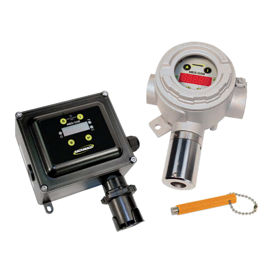
MGS-550 Fixed Gas Detector Key Product Features • Enclosure options: o General-purpose (GP): ABS plastic housing (rectangular) o Explosion-proof (XP): Aluminum housing (round) • Power options (refer to section 9.1: General Specifications on page 62): o 24 VAC o 19.5 to 28.5 VDC •... -
Page 8: General Purpose Option
MGS-550 Fixed Gas Detector General Purpose Option P/N: 1100-1000 Version 1 1.800.561.8187 information@itm.com www. .com... -
Page 9: Explosion Proof Option
MGS-550 Fixed Gas Detector Explosion Proof Option P/N: 1100-1000 Version 1 1.800.561.8187 information@itm.com www. .com... -
Page 10: Sensor Styles
MGS-550 Fixed Gas Detector Sensor Styles For General Purpose (GP) Enclosure For Explosion Proof (XP) Enclosure P/N: 1100-1000 Version 1 1.800.561.8187 information@itm.com www. .com... -
Page 11: Installation
28.5 VDC or 24 VAC). Refer to section 9: Technical Data on page 62. This ultimately determines the distance the instrument can be mounted from the controller or power supply. The MGS-550 must be powered by either: • a suitable UL/CSA/IEC 60950 certified power supply that is isolated from line voltage by double insulation, or •... -
Page 12: Mechanical Installation
Use the drilling template for proper positioning (see Installation Guide P/N 1100-0999). • Ensure that any installed sensor is pointing downwards. • Bacharach recommendations using M5 bolts (or smaller) with hex socket caps to mount the device. Electrical Installation 3.4.1 Preparations Ensure wiring for relays and connections for sensor(s) are made before applying power. - Page 13 MGS-550 Fixed Gas Detector P/N: 1100-1000 Version 1 1.800.561.8187 information@itm.com www. .com...
-
Page 14: Power And Signal Wiring
MGS-550 Fixed Gas Detector 3.4.2 Power and Signal Wiring • Using appropriate cable glands and/or conduit, connect the wires for power and signal to the appropriate terminal as indicated in the figure and wiring table that follow. • Polarity must not be reversed. -
Page 15: Relay Wiring
MGS-550 Fixed Gas Detector 3.4.3 Relay Wiring At voltages > 30 VAC or > 42.2 VDC, the relay cables must be enclosed in protective conduit, or double-insulated cables must be used. WARNING • Using appropriate cable glands and/or conduit, connect the wires for relay 1, relay 2, and relay 3 to the terminals (see previous wiring figure) as indicated in the following wiring table. -
Page 16: Installation Of Remote Sensing Head
MGS-550 Fixed Gas Detector 3.4.4 Installation of Remote Sensing Head • Remove a blind-plug from the enclosure (if applicable). • Feed the connector of the sensor (see below, left) through a cable gland or conduit (if applicable), through the opening of the enclosure, and then into the enclosure. -
Page 17: Connecting One Or More Mgs-550S To A Bacharach Controller
System, are configured identically. See section 4.4.5: Modbus Configuration (MB-xx) on page 35. • If the MGS-550 is at the end of the Modbus network, the terminating resistor must be set to “IN”. All other instrument terminating resistor must be set to “OUT” (factory default). See section 4.4.5: Modbus Configuration (MB-xx) on page 35. -
Page 18: Operation
MGS-550 Fixed Gas Detector SECTION 4. OPERATION Overview of Normal Operation Before leaving the instrument for normal operation, check the configuration for proper settings and check calibration. WARNING 4.1.1 Applying Power and the Start-up Sequence After applying power, the instrument will go through a start-up sequence (LED test, software version, and initialization) and start the warm-up period. -
Page 19: Verifying Analog Signals
• 0 to 10V • 2 to 10 V The MGS-550 uses different current values to indicate various modes of operation. See section 9.1: General Specifications on page 62 for additional information. 4.1.3 Verifying the Digital Modbus Signal The MGS-550 provides a Modbus RTU digital interface. All status messages and most parameters which can be accessed and/or configured through the menu can also be accessed and/or configured via a Building Management using a Modbus network. - Page 20 MGS-550 Fixed Gas Detector Symbol/Message Description The measuring range of the sensor has been exceeded (“upper hockey sticks” symbol). The sensor drifted negative (<0) (“lower hockey sticks” symbol). If a fault has been detected, the display toggles between gas name and "Exxx", and the green power LED is off.
-
Page 21: Menus
NOTICE Menus 4.2.1 General Navigation The MGS-550 offers two methods of navigating through the menu. • Use the non-intrusive magnetic wand (tapping above the “magnetic” icons with dashes) • Use the internal push buttons (pressing the push button points). -
Page 22: Checking Status And Changing Parameter Values
MGS-550 Fixed Gas Detector Magnetic Switch Points Internal Push Function(s) Button Points Tapping/pressing and holding the [i] key for more than 3 seconds gives access to the user menu (which displays the firmware version first). It is also used to return to the next higher menu item without saving any changes (“escape”). -
Page 23: Menu Overview
MGS-550 Fixed Gas Detector 4.2.4 Menu Overview The menu is divided in functions and parameters. Individual parameters are grouped into logical menus. Function Description F-01 00 = instrument online, 01 = instrument OFFLINE F-02 1 = zero sensor 1, 2 = zero sensor 2... - Page 24 MGS-550 Fixed Gas Detector P/N: 1100-1000 Version 1 1.800.561.8187 information@itm.com www. .com...
-
Page 25: Functions
MGS-550 Fixed Gas Detector Functions 4.3.1 Offline Mode (F-01) In OFFLINE mode the instrument does not respond to alarm conditions, but allows the execution of functions and the setting of parameters. OFFLINE mode is useful in eliminating false alarms while performing maintenance. -
Page 26: Parameter Menu (F-05)
MGS-550 Fixed Gas Detector Test Description The relay test changes the state of each relay. Use the [UP] / [DOWN] key to toggle the relay. Tap [ENTER] to test the next relay. Tap [i] to exit the function. Relay Note that changing the state of the relays can trigger alarms in connected equipment. -
Page 27: De-Register One Sensor (F-07)
MGS-550 Fixed Gas Detector New sensors all have address 100. The first sensor registered will be sensor #1 and the second sensor #2. Resetting sensor registration through F-08 will reset them all to 100; then they need to be registered one at a time. -
Page 28: Diagnostics, System Information And Fault Data (F-09)
MGS-550 Fixed Gas Detector Before unplugging ANY sensor, it must be de-registered using function F-07. Failure to do this will require you to de-register all sensors using F-08 (with the sensors still connected to the main electronics), remove the sensors, and then re-install and re- register the sensors one at a time using function F-06. -
Page 29: Parameters
MGS-550 Fixed Gas Detector Parameters 4.4.1 Sensor 1 Settings (S1-xx) and Sensor 2 Settings (S2-xx) if Connected S1 & S2 Param Name (n=1 or 2) Description (n=1 or 2) S1-01 S2-01 Sensor n Gas Name Abbreviated Gas Name S1-02 S2-02... - Page 30 MGS-550 Fixed Gas Detector A fixed hysteresis of 5% of full scale is set in order to avoid chatter at an alarm threshold. NOTICE For all instruments except oxygen, the alarm occurs on gas concentrations that increase beyond the set-points.
- Page 31 MGS-550 Fixed Gas Detector Alarm hierarchy exists. An A2 alarm overrides an A1 alarm on the display. However, the A1 and A2 states operate independently. An example follows. • A1 is acknowledgeable • A2 is not acknowledgeable • The gas concentration is such that it triggers A1 and A2 Acknowledging will cause the A1 relay to release.
-
Page 32: Relay Designation (Rx-Xx)
MGS-550 Fixed Gas Detector 4.4.2 Relay Designation (RX-xx) Parameter Name Description R1-01 Relay 1 Contact Behavior Select behavior for Relay 1: 0 = NO, 1 = Failsafe. R1-02 Relay 1 Source Select alarm configuration (01 to 14) to activate Relay 1:... -
Page 33: Alarm Configuration (Af-Xx)
MGS-550 Fixed Gas Detector 4.4.3 Alarm Configuration (AF-xx) Parameter Name Description AF-01 Alarm ON Delay Value 00 = no delay, 01 to 15 = delay in minutes. If an alarm ON delay is set, the gas concentration has to be... -
Page 34: Analog Output Configuration (Ax-Xx)
MGS-550 Fixed Gas Detector 4.4.4 Analog Output Configuration (AX-xx) Parameter Name Description A1-01 Analog Output 1 1 = Sensor 1 Source 2 = Sensor 2 A1-02 Analog Output 1 Type 0 = 0 to 5 V 1 = 1 to 5 V... -
Page 35: Modbus Configuration (Mb-Xx)
Select alarm configuration (01 to 14) to activate Buzzer. 00 = Buzzer disabled Each MGS-550 has a built-in buzzer which can be designated to any alarm configuration. Refer to section 4.4.2: Relay Designation (RX-xx) on page 32 for a list of alarm configurations. -
Page 36: Maintenance
Every 6 Check LEDs for proper operation. Months* Check for proper triggering of alarm devices. Calibrate the sensor or contact Bacharach for sensor exchange with factory- calibrated sensor. As Required Replace sensor(s). See section 5.4 Sensor Maintenance on page 44. -
Page 37: General Procedure
MGS-550 Fixed Gas Detector When entering the functions F-02 (zero adjustment) or F-03 (span adjustment), the instrument will automatically enter OFFLINE mode. The instrument will remain OFFLINE until either the OFFLINE mode is canceled using function F-01 (see section 4.3.1: Offline... -
Page 38: Zero Adjustment
MGS-550 Fixed Gas Detector 5.2.3 Zero Adjustment Ambient air can be used to zero the sensor instead of nitrogen or synthetic air only if the area is known to be free of the target gas or any gas to which the sensor may be cross- sensitive (as listed on the sensor data sheet). -
Page 39: Troubleshooting
MGS-550 Fixed Gas Detector • Apply target gas; if required a sufficiently high concentration (low concentration for oxygen displacement) to trigger alarms. • The display will show the current gas concentration value. • Once the alarm thresholds are exceeded, verify that all designated gas alarm relays are activated and the analog and digital outputs properly transmitted the corresponding gas concentrations. -
Page 40: Instrument Electronics Critical (E100) Faults
MGS-550 Fixed Gas Detector Attribute Description D-04 Number of days since the last span calibration of Sensor 1. This value automatically resets to 0000 after completing a span adjustment via F-03. D-05 Number of days since the last span calibration of Sensor 2. This value automatically resets to 0000 after completing a span adjustment via F-03. -
Page 41: Non-Critical (E300) Faults
MGS-550 Fixed Gas Detector Code Critical Fault Possible Causes Remedy 0800 Sensor 1 error Sensor is registered, Sensor was removed. Replace sensor. but not responding Sensor was replaced without re-registration. 1000 Sensor 2 error correctly or the wrong Register sensor. See section 4.3.6: Register sensor installed. -
Page 42: Sensor Faults
MGS-550 Fixed Gas Detector Non-Critical Code Possible Causes Remedy Fault Verify proper communications settings for the network. Refer to section 4.4.5: Modbus Configuration (MB-xx) on page 35 for more information. A possible hardware problem may exist. Contact the factory. 0040... - Page 43 MGS-550 Fixed Gas Detector Code Sensor Fault Possible Causes Remedy long to receive buffer) occurs then call service 0200 RS485 checksum fault Checksum error in received packet Power-cycle. If it re- occurs then call service 0400 Modbus fault Packet timeout. Modbus message Power-cycle.
-
Page 44: Sensor Maintenance (General Purpose Housings)
MGS-550 Fixed Gas Detector Sensor Maintenance (General Purpose Housings) 5.4.1 Components Overview This product uses semiconductors which can be damaged by electrostatic discharge (ESD). When handling the PCB, care must be taken so that the electronics is not damaged. CAUTION If the instrument has two sensors installed, and both sensors, modules or heads should be replaced, then replace and register them one at a time. -
Page 45: Replacing The Sensor Module
MGS-550 Fixed Gas Detector 5.4.2 Replacing the Sensor Module See illustration in section 5.4.1: Components Overview on page 44. Step Description Power down the instrument. Unscrew M40 locknut (item 10). Pull sensor cap (item 9) down. Remove sensor spacer (optional on certain sensors) if it is in place. -
Page 46: Replacing The Sensor Control Board
MGS-550 Fixed Gas Detector 5.4.3 Replacing the Sensor Control Board See illustration in section 5.4.1: Components Overview on page 44. Step Description Power down the instrument. Unscrew M40 locknut (item 10). Pull sensor cap (item 8) down. Remove sensor spacer (optional on certain sensors) , if it is in place (if applicable). -
Page 47: Replacing The Local Sensing Head Assembly
MGS-550 Fixed Gas Detector 5.4.4 Replacing the Local Sensing Head Assembly See illustration in section 5.4.1: Components Overview on page 44. Step Description Deregister the old sensor (see section 4.3.7: De-register One Sensor (F-07) on page 27). Power down the instrument. -
Page 48: Adding A Second Sensor
MGS-550 Fixed Gas Detector 5.4.5 Adding a Second Sensor Step Description Power down the instrument. Open the housing. For the GP housing: • Loosen the four screws of the lid using an M5 hex key and remove the lid. Using a flat-head screwdriver, loosen the three screws and carefully pull out the bezel from the enclosure. -
Page 49: Replacing The Remote Sensing Head Assembly
MGS-550 Fixed Gas Detector 5.4.6 Replacing the Remote Sensing Head Assembly See illustration in section 5.4.1: Components Overview on page 44. Step Description Power down the instrument. Loosen the four screws of the lid using an M5 hex key and remove the lid. -
Page 50: Sensor Maintenance (Explosion Proof Housings)
MGS-550 Fixed Gas Detector Sensor Maintenance (Explosion Proof Housings) 5.5.1 Components Overview This product uses semiconductors which can be damaged by electrostatic discharge (ESD). When handling the PCB, care must be taken so that the electronics is not damaged. CAUTION If the instrument has two sensors installed, and both sensors, modules or heads are to be replaced, then replace and register them one at a time. -
Page 51: Replacing The Sensor Module
MGS-550 Fixed Gas Detector 5.5.2 Replacing the Sensor Module See illustration in section 5.5.1: Components Overview on page 50. Step Description Power down the instrument. Loosen the set screw (see photos to right) in the sensing head cap (item 8) using a 1.5 mm hex wrench. -
Page 52: Replacing The Sensor Control Board
MGS-550 Fixed Gas Detector 5.5.3 Replacing the Sensor Control Board See illustration in section 5.5.1: Components Overview on page 50. Step Description Power down the instrument. Loosen the set screw (see photos to right) in the sensing head cap (item 8) using a 1.5 mm hex wrench. -
Page 53: Replacing The Local Sensing Head Assembly
MGS-550 Fixed Gas Detector 5.5.4 Replacing the Local Sensing Head Assembly See illustration in section 5.5.1: Components Overview on page 50. Step Description Power down the instrument. Loosen the set-screw (1.5 mm hex key) and unscrew lid from instrument. Using a flat-head screwdriver,... -
Page 54: Replacing The Remote Sensing Head Assembly
MGS-550 Fixed Gas Detector 5.5.5 Replacing the Remote Sensing Head Assembly See illustration in section 5.5.1: Components Overview on page 50. Step Description Power down the instrument. Loosen the set-screw (1.5 mm hex key) and unscrew lid from instrument. Using a flat-head screwdriver,... -
Page 55: Replacing The Instrument Electronics
MGS-550 Fixed Gas Detector Replacing the Instrument Electronics This product uses semiconductors which can be damaged by electrostatic discharge (ESD). When handling the PCB, care must be taken so that the electronics are not damaged. CAUTION Step Description The user should note parameters, settings such as alarm setpoints, relay configurations, etc., as the unit will have factory settings after replacement of the processor board Power down the instrument. -
Page 56: Replacing The Interface Board
MGS-550 Fixed Gas Detector Replacing the Interface Board This product uses semiconductors which can be damaged by electrostatic discharge (ESD). When handling the PCB, care must be taken so that the electronics are not damaged. CAUTION Step Description Power down the instrument. -
Page 57: Factory Default Settings
MGS-550 Fixed Gas Detector SECTION 6. FACTORY DEFAULT SETTINGS Parameter Name Factory Default Changed To S1-01 Sensor 1 Gas Name Sensor dependent S1-02 Sensor 1 UID 5-digits, alphanumeric S1-03 Sensor 1 Low Alarm Sensor dependent ppb/ppm/%LEL/Vol% S1-04 Sensor 1 Medium Alarm... - Page 58 MGS-550 Fixed Gas Detector Parameter Name Factory Default Changed To R3-01 Relay 3 Contact Behavior / 0 = normally open Failsafe R3-02 Relay 3 Source 1-Sensor system = 04 AF-01 Alarm ON Delay Value 00 = no delay AF-02 Alarm OFF Delay Value...
-
Page 59: Sensor Principle
MGS-550 Fixed Gas Detector SECTION 7. SENSOR PRINCIPLE Electrochemical Sensors Electrochemical sensors measure the partial pressure of gases under atmospheric conditions. The monitored ambient air diffuses through a membrane into the liquid electrolyte in the sensor. The electrolyte contains a measuring electrode, a counter-electrode and a reference electrode. An electronic “potentiostat”... -
Page 60: Infrared Sensors
MGS-550 Fixed Gas Detector Certain substances in the environment to be monitored may impair the sensitivity of the sensors: 1. Materials containing silicone or silicone rubber/putty 2. Corrosive gases such as hydrogen sulfide, sulfur oxide, chlorine, hydrogen NOTICE chloride, etc. -
Page 61: Disposing Of The Instrument
Therefore it must not be disposed of through these channels. The device can be returned to your national Bacharach Sales Organization for disposal. Please do not hesitate to contact Bacharach if you have any further questions on this issue. Disposing of Electrochemical Sensors Dispose of sensors in accordance with local laws. -
Page 62: Technical Data
MGS-550 Fixed Gas Detector SECTION 9. TECHNICAL DATA General Specifications Category Specifications Signals to Analog Current Normal operation: ............. 4 to 20 mA Central Drift below zero: ............. 3.8 mA Controller Measuring range exceeded: ......... 20.5 mA Instrument fault: ............≤ 1.2 mA Fault on analog interface: .......... -
Page 63: Sensor Specifications
Approvals Company USA Certification (for units assembled in USA): Certifications Bacharach (USA) is a TÜV-SÜD certified company. Ireland Certification (for units assembled in Ireland): Murco (a Bacharach Company) is an NSAI certified company. Sensor Specifications Electro-Chemical Semi-Conductor Catalytic Bead Infrared... -
Page 64: Modbus Registers
MGS-550 Fixed Gas Detector IR Sensors Formula Measuring Range 0 to 5,000 ppm = 0 to 0.5 Vol% 0 to 10,000 ppm = 0 to 1 Vol% 0 to 20,000 ppm = 0 to 2 Vol% Carbon Dioxide 0 to 30,000 ppm = 0 to 3 Vol%... -
Page 65: Analog Input Registers
MGS-550 Fixed Gas Detector 9.3.1 Analog Input Registers Analog input registers are read only and use Modbus function code 04 (Read Input Register). Description Range Units Param 16-bit Current Fault Code Instrument See 5.3.4: 30001 D-01 electronics Non-Critical E300) Faults on page 41 and 5.3.3... - Page 66 MGS-550 Fixed Gas Detector Description Range Units Param 30028 Sensor 1 Instrument electronics UID Char 1,2 0 to 9; a to z ASCII Text 30029 Sensor 1 Instrument electronics UID Char 3,4 0 to 9; a to z ASCII Text...
-
Page 67: Analog Output Registers
MGS-550 Fixed Gas Detector Description Range Units Param 30055 Sensor 2 Module SID Char 3,4 0 to 9; a to z ASCII Text 30056 Sensor 2 Module SID Char 5,NULL 0 to 9; a to z ASCII Text 9.3.2 Analog Output Registers Analog output registers are readable (using function code 03) and writable (using function code 06). - Page 68 MGS-550 Fixed Gas Detector Description Range Units Menu 40019 Sensor 2 High Alarm ppb, ppm, %LEL or 0 to sensor full Unit S2-05 Vol%. (Note: % LEL and Vol% sensors scale dependent are always displayed as “x 10” the actual value.
-
Page 69: Input Status Flags
MGS-550 Fixed Gas Detector Description Range Units Menu 40040 Critical Fault Latch AF-03 40041 Instrument electronics fault code See 5.3.4: Non- D-01 Critical (E300) Faults on page 41 and 5.3.3 Critical Faults on page 40 40042 Instrument electronics last fault See 5.3.4: Non-... -
Page 70: Output Status Flags
MGS-550 Fixed Gas Detector Description Range 10015 Sensor 2 Saturation Overflow 0 or 1 = gas > full scale 10016 Sensor 2 Saturation Underflow 0 or 1 = gas < 0 10017 Sensor 2 Start-up 0 or 1 = start-up... - Page 71 MGS-550 Fixed Gas Detector Description Range 00007 Analog Output Zero Test. Setting this to one 0 or 1 = test in process drives the analog outputs to their minimum value. This depends on the configuration of the analog output. •...
-
Page 72: Ordering Information
SECTION 10. ORDERING INFORMATION 10.1 MGS-550 Instrument Only In the descriptions below, "MGS-550 Gas Detector" includes an instrument and one sensing head mounted directly to the instrument housing. Remote or secondary local sensors must be ordered as separate items. NOTICE... - Page 73 MGS-550 Fixed Gas Detector MGS-550 Gas Detector, IP66 with IP66 Sensor Installed at the Factory 6600-8040 MGS-550 Gas Detector, IP66, SC, R22, 0-1000 ppm 6600-8041 MGS-550 Gas Detector, IP66, SC, R32, 0-1000 ppm 6600-8042 MGS-550 Gas Detector, IP66, SC, R134a, 0-1000 ppm...
-
Page 74: Mgs-550 Ex D Instruments With Sensing Heads
NOTICE MGS-550 Ex d Instruments with Sensing Heads MGS-550 Instrument ONLY, Ex d Enclosure (For remote sensor applications, order sensing heads 6600-8500 below) 10.4 MGS-550 Gas Detector, Ex d Enclosure with Ex d Sensing Head... -
Page 75: Mgs-550 5M Remote And Second Sensing Heads
6600-8575 MGS-550 Gas Detector, Ex d, SC, Ethylene, 0-2000 ppm 10.5 MGS-550 5m Remote and Second Sensing Heads Below is the MGS-550 Sensing Head Part Number Configurator. Part number format is: 6600-8ABC. NOTICE All 5m remote and second, directly mounted sensing heads must be ordered separately. - Page 76 MGS-550 Fixed Gas Detector Codes Sensing Head Target Gas and Range "B & C" "B & C" Select the Target Gas and Range, Noting the "B & C" Codes IR, CO , 0-5000 ppm IR, CO , 0-10000 ppm IR, CO...
- Page 77 MGS-550 Fixed Gas Detector Codes Sensing Head Target Gas and Range "B & C" "B & C" Select the Target Gas and Range, Noting the "B & C" Codes SC, HFO1234YF, 0-1000 ppm SC, HFO1234ZE, 0-1000 ppm SC, R22, 0-10000 ppm...
-
Page 78: 10.6 Mgs-550 Replacement Parts And Accessories
MGS-550 Replacement Parts and Accessories Replacement interface I/O PCB Assembly, MGS-550 GP. Base PCB with terminal blocks for IP66 6600-8400 housing. Replacement interface I/O PCB Assembly, MGS-550 XP. Base PCB with terminal blocks for Ex d 6600-8401 housing. 6600-8402 Replacement display PCB Assembly, MGS-550 GP/XP 6600-8403 Ribbon Cable, MGS-550 GP/XP. -
Page 79: Declaration Of Conformity
DECLARATION OF CONFORMITY NOTE: The Directives or Harmonized Standards to which this product has been evaluated may have changed. Bacharach, Inc. however continues to market this product under a presumption of conformity even though the Standards may no longer be harmonized.
Need help?
Do you have a question about the MGS-550 and is the answer not in the manual?
Questions and answers