Sign In
Upload
Download
Table of Contents
Contents
Add to my manuals
Delete from my manuals
Share
URL of this page:
HTML Link:
Bookmark this page
Add
Manual will be automatically added to "My Manuals"
Print this page
×
Bookmark added
×
Added to my manuals
Manuals
Brands
Bacharach Manuals
Gas Detectors
MGS-400
User manual
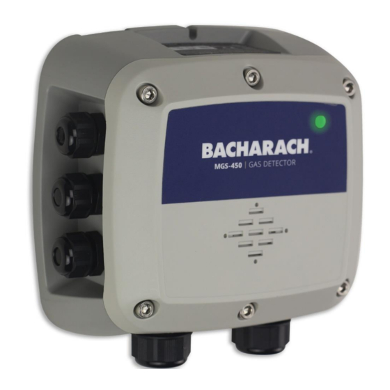
Bacharach MGS 400 User Manual
Fixed gas detectors for safety compliance applications
Hide thumbs
Also See for MGS 400
:
User manual
(81 pages)
1
2
Table Of Contents
3
4
5
6
7
8
9
10
11
12
13
14
15
16
17
18
19
20
21
22
23
24
25
26
27
28
29
30
31
32
33
34
35
36
37
38
39
40
41
42
43
44
45
46
47
48
49
50
51
52
53
54
55
56
page
of
56
Go
/
56
Contents
Table of Contents
Troubleshooting
Bookmarks
Table of Contents
Table of Contents
1 Introduction
About this Manual
Conventions
Short Form Instructions
Iconography
General Safety Statements
Safe Connection of Electrical Devices
2 Product Descriptions
Intended Uses / Applications
Transmitter Construction
Power Options
Diagnostic / Status LED
Configurable Output Signals
User Interface
Technical Specifications
Components
MGS-410 Components
MGS-450 Components
MGS-460 Components
3 Installation
General Information
Restrictions
Mechanical Installation
Electrical Installation
Preparations
Power & Signal Wiring
Relay Wiring
Installation of Remote Sensing Head
Connecting to MGS-408 Gas Detection Controller
Modbus RTU RS-485 Interface
Confirming Instrument Functionality
4 Operation
Overview of Normal Operation
Applying Power & the Start-Up Sequence
Verifying Analog Signals
Verifying the Modbus Signal
Status Indication
Switch Functions
Reset System to Factory Default Settings
MGS-400 Smartphone Application
Enable Bluetooth Connection
Checking Status
Instrument Configuration
Change Alias
Change Bluetooth Passcode
Change Unlock Code
Alarm Configuration
Low Alarm Setpoint
Reset to Factory Defaults
Address
Alarm Latching
High Alarm Setpoint
Modbus Configuration
Analog Output Range
Baud Rate
Enable 120Ω Termination
Output Configuration
Parity
Stop Bits
Alarm Delay
Analog Zero Adjust
Buzzer
Relay Failsafe
Analog Span Range
5 Care & Maintenance
Maintenance Intervals
Adjustments
Introduction
General Calibration Procedure
Zero Adjustment
Span Adjustment
System Bump Test
Troubleshooting
Hexadecimal Format
Fault Codes
Sensor Maintenance
Replacing the Sensor Module
Cleaning the Instrument
6 Additional Information
Sensor Principle
Electrochemical Sensors
Catalytic Bead Sensors
Semiconductor Sensors
Infrared Sensors
Disposing of the Instrument
Disposing of the Electrical & Electronic Equipment
Disposing of Sensors
Sensor Specifications
Modbus Registers
Integration - Dynamic Sensor Data
Integration - Static Sensor Data
Integration - General System Setup
Integration - Calibration
Integration - User Debug Tools
MGS Compatibility - Status Flags
Integration - Status Flags
MGS Compatibility - Clear Special States
Integration - User Tasks
7 Ordering Information
Part Numbers
MGS-400 Gas Detector Configurations
MGS-400 Series Accessories
Service Center Locations
Advertisement
Quick Links
1
Electrical Installation
Download this manual
See also:
User Manual
1100-2294 Rev 1
1
Table of
Contents
Previous
Page
Next
Page
1
2
3
4
5
Advertisement
Table of Contents
Need help?
Do you have a question about the MGS 400 and is the answer not in the manual?
Ask a question
Questions and answers
Related Manuals for Bacharach MGS 400
Gas Detectors Bacharach MGS-400 User Manual
Refrigerant gas detectors for machinery rooms, cold rooms & freezers (81 pages)
Gas Detectors Bacharach MGS-460 Quick Start Manual
Refrigerant gas detector for machinery rooms, cold rooms & freezers (14 pages)
Gas Detectors Bacharach MGS-410 Quick Start Manual
Refrigerant gas detector for machinery rooms, cold rooms & freezers (14 pages)
Gas Detectors Bacharach HFO1234ZE Installation And Operation Manual
Infrared gas detector (59 pages)
Gas Detectors Bacharach MGS-550 User Manual
Fixed gas detector (79 pages)
Bacharach MGS-550 - Dual Sensor Gas Detector Quick Start Guide
(article)
Gas Detectors Bacharach MGS-450 User Manual
Fixed gas detectors for safety compliance applications (56 pages)
Gas Detectors Bacharach MGS-350 Installation And Operation Manual
(44 pages)
Gas Detectors Bacharach MVR-300 User Manual
Refrigerant gas detector for occupied spaces (49 pages)
Gas Detectors Bacharach H25-IR PRO Manual
(10 pages)
Gas Detectors Bacharach Multi-Zone 3015-6143 Installation Manual
Tower light (2 pages)
Gas Detectors Bacharach H25-IR Instruction
Ir sensor replacement (4 pages)
Gas Detectors Bacharach LEAKATOR 10 Instruction Manual
Combustible gas detector (24 pages)
Gas Detectors Bacharach LEAKATOR 10 Instructions Manual
Combustible gas detector (29 pages)
Gas Detectors Bacharach GDA-1600 Instructions Manual
Gas alarm 16-channel controller (54 pages)
This manual is also suitable for:
Mgs-410
Mgs-450
Mgs-460
Table of Contents
Print
Rename the bookmark
Delete bookmark?
Delete from my manuals?
Login
Sign In
OR
Sign in with Facebook
Sign in with Google
Upload manual
Upload from disk
Upload from URL


Need help?
Do you have a question about the MGS 400 and is the answer not in the manual?
Questions and answers