Table of Contents

Related Manuals for Bacharach HFO1234ZE


Summary of Contents for Bacharach HFO1234ZE
- Page 1 Infrared Gas Detector Installation and Operation Manual Instruction 6490-9000 September 2016 Revision 4 Product Leadership x x Training x Service x Reliability 1.888.610.7664 www.calcert.com sales@calcert.com...
- Page 2 MGS-250 Manual WARRANTY POLICY BACHARACH, INC. WARRANTS THIS GAS DETECTOR TO BE FREE FROM DEFECTS IN MATERIALS AND WORKMANSHIP FOR A PERIOD OF ONE YEAR FROM THE DATE OF PURCHASE BY THE ORIGINAL OWNER. IF THE PRODUCT SHOULD BECOME DEFECTIVE WITHIN THIS WARRANTY PERIOD, WE WILL REPAIR OR REPLACE IT AT OUR DISCRETION.
- Page 3 PROTECTION AND ALL RIGHTS ARE RESERVED. NO PARTY MAY USE OR COPY SUCH SOFTWARE IN ANY MANNER OR FORMAT, EXCEPT TO THE EXTENT THAT BACHARACH GRANTS THEM A LICENSE TO DO SO. IF THIS SOFTWARE IS BEING LOADED ONTO MORE THAN ONE COMPUTER, EXTRA SOFTWARE LICENSES MUST BE PURCHASED.
- Page 4 MGS-250 Manual 6490-9000 Revision 4 1.888.610.7664 www.calcert.com sales@calcert.com...
-
Page 5: Table Of Contents
MGS-250 Manual Table of Contents SECTION 1. INTRODUCTION ................ 9 1.1. Overview ...................... 9 1.2. Detection Options ..................9 1.2.1. Broadband vs. Gas Specific ..............9 1.2.2. Broadband Gas Detection ..............10 1.2.3. Detecting Specific Gases ..............11 1.3. Remote Controller Options ................ 15 1.4. - Page 6 MGS-250 Manual 5.2. Setting Parameters ..................34 5.2.1. Overview ..................34 5.2.2. Configuration Parameters ..............34 5.3. Completing Setup ..................42 SECTION 6. FUNCTIONAL TESTS AND ADJUSTMENTS ........ 43 6.1. Introduction ....................43 6.2. Bump Testing vs. Adjusting Detector Response ......... 44 6.3.
- Page 7 MGS-250 Manual List of Figures SECTION 1. INTRODUCTION ................ 9 Figure 1. MGS-250 Components ................. 9 Figure 2. Broadband Gas Groups 1-3 ..............11 Figure 3. Gas Specific MGS-250 Gas Detectors ..........12 Figure 4. Changing Gas Types and Accuracy ............. 14 SECTION 2.
- Page 8 MGS-250 Manual List of Tables SECTION 1. INTRODUCTION ................ 9 Table 1: Broadband Gas Groups and Performance (P/N 6401-0500) ....10 Table 2: Gas Specific Detector Measurement Performance ......13 Table 3: Parts List ....................15 Table 4: Technical Specifications ............... 16 SECTION 3.
-
Page 9: Introduction
MGS-250 Manual Section 1. Introduction 1.1. Overview The MGS-250 NDIR (non-dispersive infrared) is a state-of-the-art fixed gas detector which can detect a wide range of refrigerant gases. The MGS-250 can be used on a stand-alone basis or integrated into controls or a Building Management System (BMS). -
Page 10: Broadband Gas Detection
R448A ±40% R449A ±40% R422a ±25% R422d ±20% HFO1234YF ±25% P.-11 = 2 HFO1234Ze ±25% R452A ±25% R513A ±35% P.-11 = 3 ±25% P.-11 = 4 ±35% See Section 5 for information on Parameter 11 and other configuration instructions. 6490-9000 Revision 4 1.888.610.7664... -
Page 11: Detecting Specific Gases
MGS-250 Manual Figure 2. Broadband Gas Groups 1-3 1.2.3. Detecting Specific Gases Each gas-specific gas detector (PNs 6401-0501 to 6401-0520) is shipped factory calibrated to its specific target refrigerant. Refer to Figure 3 and Table 2. 6490-9000 Revision 4 1.888.610.7664 www.calcert.com sales@calcert.com... -
Page 12: Figure 3. Gas Specific Mgs-250 Gas Detectors
MGS-250 Manual Figure 3. Gas Specific MGS-250 Gas Detectors 6490-9000 Revision 4 1.888.610.7664 www.calcert.com sales@calcert.com... -
Page 13: Table 2: Gas Specific Detector Measurement Performance
6401-0508 R410a ±3% 6401-0509 R422a ±5% 6401-0510 R422d ±5% 6401-0511 R427a ±3% 6401-0512 R507 ±5% 6401-0513 HFO1234YF ±5% 6401-0514 HFO1234Ze ±5% 6401-0515 HFO1233ZD ±5% 6401-0516 ±5% 6401-0517 R448A ±5% 6401-0518 R449A ±5% 6401-0519 R513A ±5% 6401-0520 R452A ±5% See Section 5 for information on Parameter 11 and other configuration instructions. -
Page 14: Figure 4. Changing Gas Types And Accuracy
MGS-250 Manual Part number 6401-0501 (R22) is factory calibrated to R22 and has an as-shipped R22 response accuracy of r5% of reading. The gas detector may be changed to respond to any of the other listed refrigerants (see parameter P.-11, in section 5.2). If changed, the gas detector will have a lower accuracy for the target refrigerant (without calibration). -
Page 15: Remote Controller Options
6401-0508 MGS-250, R410a 6401-0509 MGS-250, R422a 6401-0510 MGS-250, R422d 6401-0511 MGS-250, R427a 6401-0512 MGS-250, R507 6401-0513 MGS-250, HFO1234YF 6401-0514 MGS-250, HFO1234ZE 6401-0515 MGS-250, HFO1233ZD 6401-0516 MGS-250, R32 6401-0517 MGS-250, R448A 6401-0518 MGS-250, R449A 6401-0519 MGS-250, R513A 6401-0520 MGS-250, R452A 6490-9000... -
Page 16: Specifications
MGS-250 Manual 1.5. Specifications Table 4: Technical Specifications Specification Description Power Supply 24 VDC @ 0.15 A min; 24 VAC, 5 VA min @ 50/60 Hz, 2.5 W max Power Monitoring Green LED Visual Alarm Red 4-digit LED display Audible Alarm Buzzer (audible alarm), enable/disable Fault Monitoring Fault codes presented to user... -
Page 17: Mounting The Gas Detector
MGS-250 Manual Section 2. Mounting the Gas Detector 2.1. Warnings and Prerequisites WARNING: Explosion hazard! Do not mount the MGS-250 in an area that may contain flammable liquids, vapors, or aerosols. Operation of any electrical equipment in such an environment constitutes a safety hazard. CAUTION: MGS-250 contains... -
Page 18: Machinery Rooms
MGS-250 Manual 2.2.2. Machinery Rooms There is no absolute rule in determining the number of gas detectors and their locations. However, a number of simple guidelines will help to make a decision. Gas detectors monitor a point as opposed to an area. If the gas leak does not reach the detector then no alarm will be triggered. -
Page 19: Chillers
MGS-250 Manual any direct airflow. In large rooms with multiple evaporators, gas detectors should be mounted on the central line between 2 adjacent evaporators, as turbulence will result in airflows mixing. 2.2.4. Chillers In the case of small water- or air-cooled enclosed chiller units mount the gas detector so as to monitor airflow to the extract fans. -
Page 20: Figure 5. Initial Housing Separation
MGS-250 Manual Step Mounting Procedure Wall Mount Junction Box Mount Attach the MGS-250 base to Attach the MGS-250 base to the mounting surface using the junction box (using two #6 screws (provided) mounting hardware provided through two of the mounting with your junction box) holes, being careful not to through the two junction box... -
Page 21: Figure 6. Front And Back Views Of Mgs-250 Base
MGS-250 Manual Figure 6. Front and Back Views of MGS-250 Base 6490-9000 Revision 4 1.888.610.7664 www.calcert.com sales@calcert.com... -
Page 22: Wiring And Configuration
MGS-250 Manual Section 3. Wiring and Configuration 3.1. Overview Prior to wiring and configuring the MGS-250, assure the following conditions have been met: MGS-250 backplate is mounted in an appropriate location the cover panel is removed. If the cover panel was reattached after mounting, open the gas detector enclosure by pressing the top latch with a suitable screwdriver or other flat blade. -
Page 23: Wiring Supply Power (24Vac Or 24Vdc)
MGS-250 Manual 3.2. Wiring Supply Power (24VAC or 24VDC) WARNING: Incorrect wiring may permanently damage the gas detector, and void the warranty. Double check all terminations before applying power. Either 24VAC or 24VDC may be used to power the MGS-250. Connect wiring to the appropriate terminal locations (see Table 5). -
Page 24: Figure 9. Maintaining Neutral Polarity
MGS-250 Manual WARNING: The MGS-250 must be powered by either: a suitable UL 60950/CSA certified power supply that is isolated from line voltage by double insulation, or an appropriately rated UL listed/CSA Class 2 transformer. Failure to comply can result in personal injury or death. WARNING: Neutral polarity must be maintained across units. -
Page 25: Wiring Alarm Output (Analog Signal)
MGS-250 Manual 3.3. Wiring Alarm Output (Analog Signal) The MGS-250 provides an analog output signal that is proportional to the level of gas detected. NOTE: No jumpers or hardware switch settings are required to configure the analog output. This is done electronically from the front panel display. -
Page 26: Wiring The Digital Alarm Output Relay
MGS-250 Manual 3.4. Wiring the Digital Alarm Output Relay An alarm setpoint may be programmed from the front panel of the MGS-250. When the the sensed gas level exceeds the alarm setpoint, the MGS-250 enters the alarm state. An on-board relay is tied to the alarm state, so you may activate (or deactivate) external equipment based on the MGS-250’s current alarm status. -
Page 27: Modbus Network Configuration
MGS-250 Manual 3.5. Modbus Network Configuration If your application includes a Modbus network, make network connections (RS-485 A and RS-485 B) using 18 to 24 AWG shielded twisted pair wires (with 120 ohm characteristic impedance) to terminal block positions 7 and 8 (see Figure 12), noting inverted B (-) and non- inverted A (+) signal connectors per Table 8. - Page 28 MGS-250 Manual IMPORTANT: Connect the RS-485 cable shield to pin 9 (board ground). NOTE: Selection of the Modbus Address and Baud Rate is completed through the gas detector setup menu, described later. No jumpers or hardware switch settings are required to configure the Modbus communications network.
-
Page 29: Conclusion
MGS-250 Manual Figure 13. Setting Network Termination Resistors 3.6. Conclusion Once the base is mounted and all wiring is complete, align the gas detector housing and press it onto the base. The gas detector will snap into position, completing all electrical connections. Ensure the top and bottom snap locks are engaged. -
Page 30: Operation And Stabilization
IMPORTANT: It is vital when first installing the gas detector that it warms up in an atmosphere that is known not to contain any background concentrations of refrigerant. Bacharach offers portable gas detectors for this purpose. Contact the factory for more information. 4.3. Perform a Manual Zero After the gas detector stabilizes, the power LED stops flashing and is lit continuously. -
Page 31: Alarms
MGS-250 Manual 4.4. Alarms The following occurs during an alarm condition. Table 9: MGS-250 Behavior during Alarm Conditions Item Behavior During Alarm State Green LED On (solid) Display On (blinks); reports detected PPM concentration On (if enabled and after programmed delay Audible Alarm expires) Relay Output... -
Page 32: Critical Faults
MGS-250 Manual Table 10: MGS-250 Behavior during a Non-Critical Fault Item Behavior During Non-Critical Fault State Green LED On (solid) Display Shows the appropriate fault code Analog Output Operates normally Modbus Registers Modbus registers indicate the fault. 4.5.3. Critical Faults Critical faults may indicate an unrecoverable condition. -
Page 33: Configure The Gas Detector
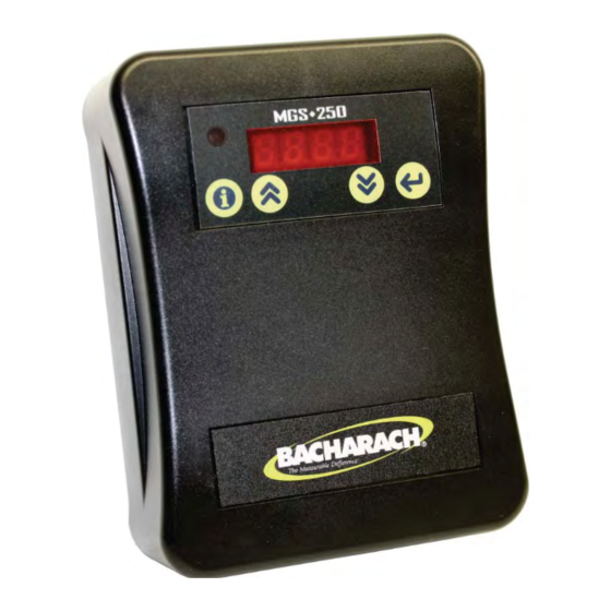
MGS-250 Manual Section 5. Configure the Gas Detector 5.1. User Interface Overview The gas detector is configured through the built in menu system. Once mounting is complete, attach the gas detector to the base and apply power. Figure 14. The User Interface of the MGS-250 The user interface consists of four pushbuttons, a four digit LED numeric display, and a power LED. -
Page 34: Setting Parameters
MGS-250 Manual 5.2. Setting Parameters 5.2.1. Overview Press and hold the information button (L) for 5 seconds (then release) to activate the parameter list. Each parameter is shown in turn by using the UP or DOWN buttons. The parameter is shown as P.-XX, with XX being the parameter value. - Page 35 MGS-250 Manual Parameter Description Alarm ON Delays Sets the ON delay time (0-15 minutes) for the alarm output signals (relay, Modbus). The default delay is 0 minutes. Alarm OFF Delays Sets the OFF delay time for the alarm output signals (relay, Modbus) in minutes (0-15).
- Page 36 Select from 4 groups of gases: R134a, R404a, R407a, R407c, R407f, R427a, R507, HFO1233ZD, R448a, R449a R422a, R422d HFO1234YF, and HFO1234Ze, R513a, R452a R22 (by itself) R32 (by itself). Specific Gas: The actual refrigerant name is shown. Select the appropriate refrigerant.
- Page 37 MGS-250 Manual Parameter Description Buzzer Mute Time Sets a time (0-59 minutes) during which the active buzzer remains muted: after the “I” button is pressed, or after Modbus register 4000 is set to 0. Baud Rate Sets the baud rate for Modbus (RS-485) communications.
- Page 38 MGS-250 Manual Parameter Description Analog Output Scaling Allows the user to select the full-scale PPM value that represents maximum analog output (e.g., 20 mA) for scaling the analog output. Adjustment range is from 100 PPM to 3500 PPM. Default = 3500 PPM.
-
Page 39: Figure 15. Analog Output Scaling Options
MGS-250 Manual Figure 15. Analog Output Scaling Options 6490-9000 Revision 4 1.888.610.7664 www.calcert.com sales@calcert.com... - Page 40 MGS-250 Manual Parameter Description Gas Test Mode Places the gas detector in gas test mode. Disabled (default) Enabled When enabled, the display continuously cycles through the following: CAL is displayed briefly. Next, the gas group number or gas type (based on product code) is displayed. Then four dashes (----) are displayed.
- Page 41 MGS-250 Manual Parameter Description Diagnostics Menu Parameter 18 provides access to the self diagnostic information. The LED display shows “DIAG” until the Enter button is pressed. Use the UP and DOWN buttons to scroll through the list of diagnostic attributes. A.-01 Current fault condition A.-02...
-
Page 42: Completing Setup
MGS-250 Manual Parameter Description Response Filtering This parameter is used to turn filtered output ON (01) or OFF (00). The default setting is ON (01). The Modbus and analog output are filtered so that responses below 75 ppm are squelched. If the display mode (P.-09) is set to ON (01) the display shows 0 for any signal level below 75 ppm. -
Page 43: Functional Tests And Adjustments
In applications where life safety is critical, calibration gas adjustment should be done quarterly (every 3 months) or on a more frequent basis. Bacharach is not responsible for setting safety practices and policies. Safe work procedures including calibration policies are best determined by company policy, industry standards, and local codes. -
Page 44: Bump Testing Vs. Adjusting Detector Response
MGS-250 Manual IMPORTANT: After initial installation, the MGS-250 should be gas tested to ensure proper operation. IMPORTANT: The testing and/or adjustment of the unit must be carried out by a suitably qualified technician, and must be done: in accordance with this manual in compliance with locally applicable guidelines and regulations. -
Page 45: Bump Testing
MGS-250 Manual the actual gas detector response level (via parameter P.-17) to ensure that the gas detector activates at the specified gas concentration. Refer to the following sections for addition information on bump testing and gas detector response adjustment. CAUTION: Before you carry out the test or adjustment: Advise occupants, plant operators, and supervisors. -
Page 46: Adjustment Using Calibration Gas
6.4. Adjustment Using Calibration Gas Adjustment Using Calibration Gas requires a gas cylinder with the appropriate gas and concentration. Note that Bacharach offers a calibration kit that consists of a calibration gas cylinder and a flow regulation valve with flexible non-absorbent tubing. - Page 47 MGS-250 Manual NOTE: For improved accuracy and response, the gas detector should be protected from excess drafts while performing the adjustment. Excess air circulation may dilute the applied calibration gas and lead to lower than expected response. Step Adjustment Using Calibration Gas Cylinders Connect the regulator to the test gas port using 3 mm or 1/8”...
- Page 48 MGS-250 Manual Step Adjustment Using Calibration Gas Cylinders If no further changes to the other parameters are required, press and hold the L button for 5 seconds to exit the Parameter list. Upon exiting the parameters list, the gas detector will enter offline mode for a period of 10 minutes. This allows time for the calibration gas to dissipate after testing.
-
Page 49: Modbus Communications
MGS-250 Manual Section 7. Modbus Communications 7.1. Introduction The MGS-250 gas detector can be configured to communicate on an RS-485 network using Modbus-RTU protocol. Before configuring the gas detector for Modbus communications, be sure your network connection is complete and your network termination switches are set appropriately. -
Page 50: Analog Input Registers
MGS-250 Manual 7.3. Analog Input Registers Analog input registers are read only and use function code 04. Table 14: Analog Input Registers Description Range Units P.-## 1000 Concentration gas level 0-100 % FS 1001 Concentration gas level 0-65,535 1002 Reserved 1003 Full scale detector level 0-65,535... -
Page 51: Analog Output Registers
MGS-250 Manual 7.4. Analog Output Registers Analog output registers are readable (using function code 03) and writable (using function code 06). Table 15: Analog Output Registers Description Range Units P.-## 2000 Alarm setpoint 75-3500 P.-02 Alarm ON delay (Alarm flag 2001 0-15 P.-04... -
Page 52: Input Status Flags
MGS-250 Manual 7.5. Input Status Flags Input Status Flags are readable (using function code 02). Table 16: Input Status Flags Description Range P.-## 3000 Alarm flag (0 or 1=Alarm) 3001 Relay state (0 or 1=energized) 3002 Detector fault (0 or 1=fault) 3003 Red LED state (0 or 1=ON) Green LED state (0 or 1=powered... -
Page 53: Troubleshooting
MGS-250 Manual Section 8. Troubleshooting 8.1. Fault Codes To comply with the requirements of EN378 and the European F-GAS regulation, gas detectors must be tested annually. However, local regulations may specify the nature and frequency of this test. The MGS-250 features sophisticated internal status monitoring and will indicate whether a fault condition exists, both on the front display (F.-XX, with XX being the fault number) and over the Modbus communications network. -
Page 54: Table 18: Fault Codes
MGS-250 Manual Table 18: Fault Codes Description Fault Code Possible Causes Code Gas Detector 0x0001 Gas Detector temperature Temperature reports > 55° C or < -35° C. Fault Gas Detector 0x0002 Temperature rate of change Temperature exceeds ~1°C/min for more Rate of than 15 minutes. -
Page 55: Diagnostics Attributes (P.-18)
Critical fault. Cycle power to the sensor and see of the fault clears. If not, contact Bacharach technical support for additional guidance. IMPORTANT: Fault F.-15 may be caused by rapid changes in temperature, and other environmental effects. If the F.-15 fault remains after the ambient temperature has stabilized, perform a manual re-zero to clear the fault. -
Page 56: Resetting Mgs-250 To Default Values
MGS-250 Manual Attribute Description Displays the elapsed time (in days) from the last gas adjustment or test. This value is automatically reset to 0000 after completing a gas adjustment via Test Mode P.-17. (Note that the new adjustment is stored using the Enter button.) The value may be reset to 0000 by pressing the ENTER button. -
Page 57: Other Symptoms
MGS-250 Manual Before performing this operation it is advisable to write down all the parameter settings, so they can be re-programmed. Step Description Access diagnostics menu P.-18. Press and hold both the UP and DOWN buttons for 5 seconds. This will cause the following to occur: All the LED segments will then light for 3 seconds The gas detector resets to the default settings The gas detector beeper sounds for 3 seconds. -
Page 58: Section 9. Replacement Parts And Accessories
Gas Detector Module, R427a Calibrated 6400-0027 Gas Detector Module, R507 Calibrated 6400-0028 Gas Detector Module, HFO1234YF Calibrated 6400-0029 Gas Detector Module, HFO1234ZE Calibrated 6400-0030 Gas Detector Module, HFO1233ZD Calibrated 6400-0031 Gas Detector Module, R32 Calibrated 6400-0032 Gas Detector Module, R448A Calibrated... -
Page 59: Eu Declaration Of Conformity
Bacharach, Inc. NOTE: The Directives or Harmonized Standards to which this product has been evaluated may have changed. Bacharach, Inc. however continues to market this product under a presumption of conformity even though the Standards may no longer be harmonized.
Need help?
Do you have a question about the HFO1234ZE and is the answer not in the manual?
Questions and answers