Table of Contents
Advertisement
Quick Links
Advertisement
Table of Contents

Subscribe to Our Youtube Channel
Related Manuals for Ubiquiti AGM5-HP-1114


Summary of Contents for Ubiquiti AGM5-HP-1114
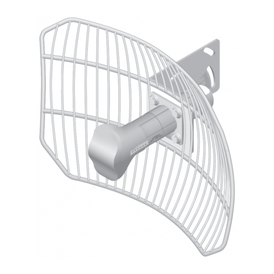
- Page 1 5 GHz High-Performance Integrated InnerFeed Antenna Model: AGM5-HP-1114...
-
Page 3: Package Contents
Introduction Thank you for purchasing the Ubiquiti Networks airGrid 5 GHz ™ High-Performance Integrated InnerFeed Antenna, model AGM5-HP-1114. This Quick Start Guide is designed to walk you through the installation of the airGrid. Package Contents 5 GHz High-Performance Integrated InnerFeed Antenna Model: AGM5-HP-1114 11x14"... -
Page 4: Installation Requirements
Ethernet connections and should be grounded through the AC ground of the PoE. We recommend that you protect your networks from the most brutal environments and devastating ESD attacks with industrial-grade shielded Ethernet cable from Ubiquiti Networks . For more details, visit www.ubnt.com/toughcable ™... - Page 5 Hardware Installation 2. Route an Ethernet cable through the cable opening of the Feed Support and connect it to the Ethernet port on the back of the Antenna Feed.
- Page 6 AGM5-HP-1114 Quick Start Guide ™ 3. Insert the Antenna Feed into the Feed Support until it locks into place. Horizontal Polarization Vertical Polarization WARNING: The orientation of the Antenna Feed and Grid Reflector must match the orientation required for your signal polarization, horizontal or vertical.
- Page 7 Hardware Installation 5. Attach the airGrid to the pole. Note: The mounting assembly can accommodate a Ø 1.25" - 2.2" pole. a. Ensure that the cable opening of the Feed Support faces down. b. Insert the M6 U Bolt into the Pole Clamp and L Bracket. c.
-
Page 8: Connecting Power Over Ethernet
AGM5-HP-1114 Quick Start Guide ™ Connecting Power over Ethernet 1. Connect the other end of the Ethernet cable from the airGrid to the Ethernet port labeled POE on the PoE Adapter. 2. Connect an Ethernet cable from your LAN to the Ethernet port labeled LAN on the PoE Adapter. - Page 9 Accessing airOS Accessing airOS Verify connectivity in the airOS Configuration Interface. 1. Make sure that your host machine is connected via Ethernet to the airGrid. 2. Configure the Ethernet adapter on your host system with a static IP address on the 192.168.1.x subnet. 3.
-
Page 10: Installer Compliance Responsibility
Since Ubiquiti Networks equipment can be paired with a variety of antennas and cables, the Antenna and Output Power fields are provided to the professional installer to assist in meeting... -
Page 11: Specifications
Specifications Specifications AGM5-HP-1114 Dimensions 370 x 270 x 264 mm (Mount Included) Weight 1.440 kg (Mount Included) Networking Interface (1) 10/100 Ethernet Port Enclosure Outdoor UV Stabilized Plastic Frequency 5470 – 5825 MHz* Gain 23 dBi Output Power 25 dBm Max. -
Page 12: Electrical Safety Information
Buyer for breach of warranty and shall constitute fulfillment of all liabilities of UBIQUITI NETWORKS with respect to the quality and performance of the Products. UBIQUITI NETWORKS reserves the right to inspect all defective Products (which must be returned by Buyer to UBIQUITI NETWORKS factory freight prepaid). -
Page 13: Warranty Conditions
Return Materials Authorization (RMA) number from UBIQUITI NETWORKS. Products returned without an RMA number will not be processed and will be returned to Buyer freight collect. UBIQUITI NETWORKS shall have no obligation to make repairs or replacement necessitated by catastrophe, fault, negligence, misuse, abuse, or accident by Buyer, Buyer’s customers or... -
Page 14: Industry Canada
AGM5-HP-1114 Quick Start Guide ™ NOTE: This equipment has been tested and found to comply with the limits for a Class A digital device, pursuant to part 15 of the FCC Rules. These limits are designed to provide reasonable protection against harmful interference when the equipment is operated in a commercial environment. -
Page 15: Rf Exposure Warning
Compliance RF Exposure Warning The antennas used for this transmitter must be installed to provide a separation distance of at least 2.52 m from all persons and must not be located or operating in conjunction with any other antenna or transmitter. Les antennes utilisées pour ce transmetteur doivent être installé... - Page 16 AGM5-HP-1114 Quick Start Guide ™ Deutsch Die Europäische Richtlinie 2002/96/EC verlangt, dass technische Ausrüstung, die direkt am Gerät und/oder an der Verpackung mit diesem Symbol versehen ist , nicht zusammen mit unsortiertem Gemeindeabfall entsorgt werden darf. Das Symbol weist darauf hin, dass das Produkt von regulärem Haushaltmüll getrennt entsorgt werden sollte.
-
Page 17: Declaration Of Conformity
Declaration of Conformity Česky UBIQUITI NETWORKS tímto prohla uje, e tento UBIQUITI NETWORKS device, je ve shod se základními po adavky a dal ími p [Czech] íslu n mi ustanoveními sm rnice 1999/5/ES. - Page 18 UBIQUITI NETWORKS device, megfelel a vonatkozó alapvetõ [Hungarian] követelményeknek és az 1999/5/EC irányelv egyéb elõírásainak. Íslenska Hér me l sir UBIQUITI NETWORKS yfir ví a UBIQUITI NETWORKS device, er í samræmi vi grunnkröfur og a rar kröfur, sem ger ar eru í [Icelandic] tilskipun 1999/5/EC.
-
Page 20: Ubiquiti Networks Support
Email: support@ubnt.com Phone (9 a.m. - 5 p.m. PST): 408-942-1153 Online Resources Wiki Page: wiki.ubnt.com Support Forum: forum.ubnt.com Downloads: downloads.ubnt.com w w w . u b n t . c o m © 2012 Ubiquiti Networks, Inc. All rights reserved.
Need help?
Do you have a question about the AGM5-HP-1114 and is the answer not in the manual?
Questions and answers