Goodwe SMT Series User Manual
Grid-tied pv inverter
Hide thumbs
Also See for SMT Series:
- User manual (64 pages) ,
- Quick installation manual (22 pages) ,
- User manual (44 pages)
Table of Contents
Advertisement
Advertisement
Chapters
Table of Contents

Related Manuals for Goodwe SMT Series


Summary of Contents for Goodwe SMT Series
- Page 1 User Manual Grid-Tied PV Inverter SMT Series V1.3-2023-01-31...
- Page 2 GoodWe Technologies Co., Ltd. Trademarks and other GoodWe trademarks are trademarks of GoodWe Company. All other trademarks or registered trademarks mentioned in this manual are owned by GoodWe Technologies Co., Ltd. Notice The information in this user manual is subject to change due to product updates or other reasons.
-
Page 3: Table Of Contents
Content User Manual V1.3-2023-01-31 CONTENT 1 About This Manual ............1 1.1 Applicable Model ..................1 1.2 Target Audience ..................1 1.3 Symbol Definition ..................2 1.4 Updates ...................... 2 2 Safety Precaution ............3 2.1 General Safety ................... 3 2.2 DC Side: ...................... 3 2.3 AC Side ....................... - Page 4 User Manual V1.3-2023-01-31 Content 6.2 Connecting the PE Cable ................ 17 6.3 Connecting the PV Input Cable ............... 18 6.4 Connecting the AC Output Cable ............23 6.5 Communication ..................25 6.5.1 Connecting the Communication Cable ............25 6.5.2 Installing the Communication Module (optional) ..........30 6.5.3 Control the Ethernet communication via the dial switch ......31 7 Equipment Commissioning ...........
-
Page 5: About This Manual
All the installers and users have to be familiar with the product features, functions, and safety precautions. This manual is subject to update without notice. For more product details and latest documents, visit www.goodwe.com. 1.1 Applicable Model... -
Page 6: Symbol Definition
User Manual V1.3-2023-01-31 01 About This Manual 1.3 Symbol Definition Different levels of warning messages in this manual are defined as follows: DANGER Indicates a high-level hazard that, if not avoided, will result in death or serious injury. WARNING Indicates a medium-level hazard that, if not avoided, could result in death or serious injury. CAUTION Indicates a low-level hazard that, if not avoided, could result in minor or moderate injury. -
Page 7: Safety Precaution
• Strictly follow the installation, operation, and configuration instructions in this manual. The manufacturer shall not be liable for equipment damage or personal injury if you do not follow the instructions. For more warranty details, visit https://en.goodwe.com/warranty. asp. 2.2 DC Side: DANGER Connect the DC cables using the delivered DC connectors and terminals. -
Page 8: Ac Side
02 Safety Precaution User Manual V1.3-2023-01-31 2.3 AC Side WARNING • The voltage and frequency at the connecting point should meet the on-grid requirements. • An additional protective device like the circuit breaker or fuse is recommended on the AC side. -
Page 9: Product Introduction
03 Product Introduction User Manual V1.3-2023-01-31 3 Product Introduction 3.1 Application Scenarios The SMT inverter is a three-phase PV string grid-tied inverter. The inverter converts the DC power generated by the PV module into AC power and feeds it into the utility grid. The intended use of the inverter is as follows: PV String Circuit... -
Page 10: Supported Grid Types
03 Product Introduction User Manual V1.3-2023-01-31 The circuit diagram of GW60KS-MT, GW60KS-MT-EU and GW35KLS-MT is as follows. SWITCH BOOST MPPT 1+ OUT FILTER MPPT 1- AC RELAY MPPT 2+ DC SPD MPPT 2- MPPT 3+ Filter MPPT 3- Filter Filter MPPT 4+ MPPT 4- AS SPD... -
Page 11: Appearance
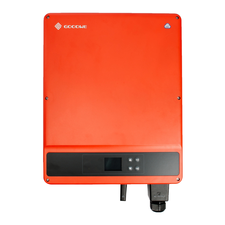
03 Product Introduction User Manual V1.3-2023-01-31 3.4 Appearance The colors of the inverter are designed as red, white, and so on. The graphic on the cover is for reference only. 3.4.1 Parts GW30KLS-MT, GW35KLS-MT, GW50KS- GW12KLV-MT, GW15KLV-MT, GW20KLV- MT, GW50KS-MT-EU, GW60KS-MT and MT, GW25K-MT, GW29.9K-MT, GW30K-MT, GW60KS-MT-EU GW36K-MT... -
Page 12: Dimension
03 Product Introduction User Manual V1.3-2023-01-31 3.4.2 Dimension GW12KLV-MT, GW15KLV-MT, GW20KLV- GW30KLS-MT, GW35KLS-MT, GW50KS- MT, GW25K-MT, GW29.9K-MT, GW30K-MT, MT, GW60KS-MT, GW50KS-MT-EU and GW36K-MT GW60KS-MT-EU 3.4.3 Indicators Indicator Status Description ON = EQUIPMENT POWER ON OFF = EQUIPMENT POWER OFF ON = THE INVERTER IS FEEDING POWER OFF = THE INVERTER IS NOT FEEDING POWER SINGLE SLOW FLASH = SELF CHECK BEFORE CONNECTING TO THE GRID... -
Page 13: Nameplate
03 Product Introduction User Manual V1.3-2023-01-31 3.4.4 Nameplate The nameplate is for reference only. Goodwe trademark, product type, and product model Technical parameters Safety symbols and certification marks Contact information and serial number... -
Page 14: Check And Storage
04 Check and Storage User Manual V1.3-2023-01-31 4 Check and Storage 4.1 Check Before Receiving Check the following items before receiving the product. 1. Check the outer packing box for damage, such as holes, cracks, deformation, and others signs of equipment damage. Do not unpack the package and contact the supplier as soon as possible if any damage is found. -
Page 15: Storage
04 Check and Storage User Manual V1.3-2023-01-31 PV Tool*N 4.3 Storage If the equipment is not to be installed or used immediately, please ensure that the storage environment meets the following requirements: 1. Do not unpack the outer package or throw the desiccant away. 2. -
Page 16: Installation
05 Installation User Manual V1.3-2023-01-31 5 Installation 5.1 Installation Requirements Installation Environment Requirements 1. Do not install the equipment in a place near flammable, explosive, or corrosive materials. 2. Install the equipment on a surface that is solid enough to bear the inverter weight. 3. - Page 17 User Manual V1.3-2023-01-31 05 Installation ALT: ≤3000m IP65 0%~100%RH Mounting Support Requirements 1. The mounting support shall be nonflammable and fireproof. 2. Make sure that the support surface is solid enough to bear the product weight load. 3. Do not install the product on the support with poor sound insulation to avoid the noise generated by the working product, which may annoy the residents nearby.
-
Page 18: Inverter Installation
05 Installation User Manual V1.3-2023-01-31 DC terminal Diagonal pliers Wire stripper Hammer drill Heat gun crimping tool Marker Level Heat shrink tube Rubber hammer Vacuum cleaner M3/M5/M 6/M8 Multimeter Cable tie Torque wrench Torque wrench 5.2 Inverter Installation 5.2.1 Moving the Inverter CAUTION Move the inverter to the site before installation. - Page 19 User Manual V1.3-2023-01-31 05 Installation Installing the mounting plate Mounting on the wall A, B, C, D: GW12KLV-MT, GW15KLV-MT, GW20KLV-MT, GW25K-MT, GW29.9K-MT, GW30K-MT, GW36K-MT. A, B, C, D, E, F: GW30KLS-MT, GW35KLS-MT, GW50KS-MT, GW60KS-MT, GW50KS-MT-EU and GW60KS-MT-EU. Mounting on the bracket (Contact the local sales center to purchase the bracket.) Mounting on the bracket (If you want other brackets, please prepare them by yourself.)
- Page 20 05 Installation User Manual V1.3-2023-01-31 Installing the Inverter For Australia only. 1.6~2N·m...
-
Page 21: Electrical Connection
User Manual V1.3-2023-01-31 06 Electrical Connection 6 Electrical Connection 6.1 Safety Precautions DANGER • Disconnect the DC switch and the AC output switch of the inverter to power off the equipment before any electrical connections. Do not work with power on. Otherwise, an electric shock may occur. -
Page 22: Connecting The Pv Input Cable
User Manual V1.3-2023-01-31 06 Electrical Connection 6.3 Connecting the PV Input Cable DANGER Confirm the following information before connecting the PV string to the inverter. Otherwise, the inverter may be damaged permanently or even cause fire and cause personal and property losses. - Page 23 User Manual V1.3-2023-01-31 06 Electrical Connection Click GW25K-MT, GW29.9K-MT, GW30K-MT, GW36K-MT, GW50KS-MT, GW60KS-MT: ≤ 1100V GW12KLV-MT, GW15KLV-MT, GW20KLV-MT, GW30KLS-MT, GW35KLS-MT: ≤ 800V Click Click...
- Page 24 User Manual V1.3-2023-01-31 06 Electrical Connection MC4 PV Connectors (1000V) Connecting the DC Input Cable Step 1 Prepare DC cables. Step 2 Crimp the crimp contacts. Step 3 Disassemble the PV connectors. Step 4 Make the DC cable and detect the DC input voltage. Step 5 Plug the PV connectors into the PV terminals.
- Page 25 User Manual V1.3-2023-01-31 06 Electrical Connection Click Click GW25K-MT, GW29.9K-MT, GW30K-MT, GW36K- MT, GW50KS-MT, GW60KS-MT, GW50KS-MT-EU and GW60KS-MT-EU: ≤ 1100V GW12KLV-MT, GW15KLV-MT, GW20KLV-MT, GW30KLS-MT, GW35KLS-MT: ≤ 800V Vaconn PV Connectors Connecting the DC Input Cable Step 1 Prepare DC cables. Step 2 Crimp the crimp contacts.
- Page 26 User Manual V1.3-2023-01-31 06 Electrical Connection 7~8mm 7~8mm Click Click GW25K-MT, GW29.9K-MT, GW30K-MT, GW36K-MT, GW50KS-MT, GW60KS-MT, GW50KS-MT-EU and GW60KS-MT-EU: ≤ 1100V GW12KLV-MT, GW15KLV-MT, GW20KLV-MT, GW30KLS-MT, GW35KLS-MT: ≤ 800V...
-
Page 27: Connecting The Ac Output Cable
User Manual V1.3-2023-01-31 06 Electrical Connection 6.4 Connecting the AC Output Cable WARNING Do not connect loads between the inverter and the AC switch directly connected to it. Select and Install RCD depending on local laws and regulations. Type A RCDs (Residual Current Monitoring Device) can be connected to the outside of the inverter for protection when the DC component of the leakage current exceeds the limit value. - Page 28 User Manual V1.3-2023-01-31 06 Electrical Connection WARNING • Pay attention to the silkscreens L1, L2, L3, N, PE on the AC terminal. Connect the AC cables to the corresponding terminals. The inverter may be damaged if the cables are connected inappropriately.
-
Page 29: Communication
4. DRED function is achieved by Ezlogger Pro or DRED COM port, please connect the Ezlogger Pro through RS485 port. You can refer to EzLogger Pro SERIES USER MANUAL. Visit https://en.goodwe.com/Ftp/EN/ Downloads/User%20Manual/GW_Ezlogger%20Pro_User%20Manual-EN.pdf to get the user manual. - Page 30 User Manual V1.3-2023-01-31 06 Electrical Connection RS485 networking scenario Inverter Inverter Inverter Internet EzLogger Pro Router RS485 RS485 RS485 Power limit networking scenario (single inverter) RS485+ RS485- Smart meter Inverter Grid Three-phase Meter circuit breaker Power limit networking scenario (multi inverters) Router Cloud RS485+...
- Page 31 User Manual V1.3-2023-01-31 06 Electrical Connection Connecting DRED or RS485 6pin Communication Cable (optional) Contat the after-sales service to get the DRED terminal if you need to use DRED function. DRED function is off by default. Start this function via SolarGo App if it's needed. DRED: For Australia only.
- Page 32 User Manual V1.3-2023-01-31 06 Electrical Connection RS485 (5PIN) Cable For Europe and India. RS485 Function RS485-A1 RS485-B1 RS485-A1 RS485-B1...
- Page 33 User Manual V1.3-2023-01-31 06 Electrical Connection Remote Shutdown and Emergency Power Off Cable (optional) Remote Shutdown (RSD): For Europe only. Emergency Power Off (EPO): For India only. RSD/EPO 6.5mm 25mm RSD/EPO +: SC-A - : SC-B 0.6~0.8N·m...
-
Page 34: Installing The Communication Module (Optional)
NOTICE • Refer to the delivered communication module user manual to get more introduction to the module. For more detailed information, visit https://en.goodwe.com/. • Remove the communication module using the unlock tool. The manufacturer shall not be liable for the port damage if the module is removed without the unlock tool. -
Page 35: Control The Ethernet Communication Via The Dial Switch
User Manual V1.3-2023-01-31 06 Electrical Connection 6.5.3 Control the Ethernet communication via the dial switch Turn the dial switch to ON, the Ethernet will be connected; turn the dial switch to OFF, the Ethernet will be disconnected. The dial switch beside the RS485 port is OFF by default. Turn the switch to ON when a single inverter is in the communication state, the terminal resistance of RS485 will be 120ohm. -
Page 36: Equipment Commissioning
07 Equipment Commissioning User Manual V1.3-2023-01-31 7 Equipment Commissioning 7.1 Check Items Before Switching Power ON Check Item The inverter is firmly installed in a clean place where is well-ventilated and easy to operate. The PE cable, DC input cable, AC output cable, and communication cable are connected correctly and securely. -
Page 37: System Commissioning
08 System Commissioning User Manual V1.3-2023-01-31 8 System Commissioning 8.1 Indicators Indicator Status Description ON = EQUIPMENT POWER ON OFF = EQUIPMENT POWER OFF ON = THE INVERTER IS FEEDING POWER OFF = THE INVERTER IS NOT FEEDING POWER SINGLE SLOW FLASH = SELF CHECK BEFORE CONNECTING TO THE GRID SINGLE FLASH = CONNECTING TO THE GRID ON = WIRELESS IS CONNECTED/ACTIVE... -
Page 38: User Interface Introduction
08 System Commissioning User Manual V1.3-2023-01-31 8.2.1 User Interface Introduction WiFi 36.00 20.5kWH 93.3kWH E-DAY E-TOTAL CARBON 01/01/2020 00:00:00 Normal 1: Communication information icon: GPRS and WiFi show the signal strength, RS485 shows the communication address. 2: Communication icon: The way of communication,There are GPRS, WiFi and RS485 3: LVRT/HVRT icon: The icon indicates that the system LVRT/HVRT function is on 4: Grid Type icon: The icon indicates that the system select Delta Grid/Star Grid 5: Power limit icon: The Power limit icon indicates that the Power limit function is on... -
Page 39: User Interface Introduction
08 System Commissioning User Manual V1.3-2023-01-31 8.2.2 User Interface Introduction The display menu through the Up, Down, Enter, Esc key to operate the menu, which Enter key is divided into long press (greater than 3s) and short press, so a total of five key operation. Press the Enter Esc key to toggle the 123 menu, use the up and down keys to select the item and change the parameters, and long press the Enter (short press is also ok for some item) to set the parameters.The display and keys of series is shown in the below figure. - Page 40 08 System Commissioning User Manual V1.3-2023-01-31 Level 1 menu Level 2 menu Level 3 menu Contry Code Contry Code Set Home Hour Select Data Select Data Running Info Configuration Month Select Data History Info Year Select Data Device Info Language Set Language Basic Date&Time...
-
Page 41: System Configuration
08 System Commissioning User Manual V1.3-2023-01-31 8.2.4 System Configuration Basic Settings Basic Settings is mainly used to set the commonly used parameters, including language settings, time settings, communication settings and safety settings for projects. And these parameters could be set by App. - Page 42 08 System Commissioning User Manual V1.3-2023-01-31...
- Page 43 08 System Commissioning User Manual V1.3-2023-01-31 Advanced Settings User must enter password to operate advanced settings because permission is required. Note: Initial password: "1111". Advanced Settings include nine Settings: 1. Power limit; 2. CT ratio; 3. Power factor; 4. Shadow scanning;...
- Page 44 08 System Commissioning User Manual V1.3-2023-01-31 Power Limit Setting...
- Page 45 08 System Commissioning User Manual V1.3-2023-01-31 History Information The history information mainly includes the information of the generating capacity of the equipment, the power generation information mainly includes the amount of electricity generation, daily power generation, monthly power generation and annual power generation information.
-
Page 46: Setting Inverter Parameters Via App
2. Set grid parameters and communication parameters of the inverter. 3. Maintain the equipment. For more details, refer to the SolarGo APP User Manual. Scan the QR code or visit https:// en.goodwe.com/Ftp/EN/Downloads/User%20Manual/GW_SolarGo_User%20Manual-EN.pdf get the user manual. SolarGo App SolarGo App User Manual 8.4 Monitoring via SEMS Portal... -
Page 47: Maintenance
User Manual V1.3-2023-01-31 09 Maintenance 9 Maintenance 9.1 Power Off the Inverter DANGER • Power off the inverter before operations and maintenance. Otherwise, the inverter may be damaged or electric shocks may occur. • Delayed discharge. Wait until the components are discharged after power off. Step 1 (optional) Send shutdown command to the inverter. - Page 48 09 Maintenance User Manual V1.3-2023-01-31 Type of fault Alarm Troubleshooting 1.Disconnect DC switch, take off DC connector, check the impedance between PV (+) & PV (-) to earth. 2. If impedance is less than 100 kΩ, please check the insulation of PV string wiring to the earth.
- Page 49 User Manual V1.3-2023-01-31 09 Maintenance Type of fault Alarm Troubleshooting Relay-check Failure DCI High 1. Disconnect the DC connector. EEPROM R/W Failure Inverter 2. Reconnect the DC connector. Failure SPI Failure 3. If the problem still exists, please call the local service office. DC Bus High GFCI Failure 1.
-
Page 50: Routine Maintenance
09 Maintenance User Manual V1.3-2023-01-31 9.5 Routine Maintenance Maintaining Item Maintaining Method Maintaining Period Check the heat sink, air intake, and air System Clean Once 6-12 months outlet for foreign matter or dust. Check the fan for proper working status, Once a year low noise, and intact appearance. -
Page 51: Technical Parameters
User Manual V1.3-2023-01-31 10 Technical Parameters 10 Technical Parameters Technical Data GW12KLV-MT GW15KLV-MT GW20KLV-MT Input Max. Input Power (kW) 15.6 19.5 Max. Input Voltage (V) MPPT Operating Voltage Range (V) 200~650 MPPT Voltage Range at Nominal 360~600 Power (V) Start-up Voltage (V) Nominal Input Voltage (V) Max. - Page 52 10 Technical Parameters User Manual V1.3-2023-01-31 Technical Data GW12KLV-MT GW15KLV-MT GW20KLV-MT Max. Output Fault Current (Peak and 160@2.8μs Duration)(A) Inrush Current (Peak and Duration) (A) 60@1.5ms Nominal Output Current (A) 31.5 39.4 54.3 Output Power Factor ~1 (Adjustable from 0.8 leading to 0.8 lagging) Max.
- Page 53 User Manual V1.3-2023-01-31 10 Technical Parameters Technical Data GW12KLV-MT GW15KLV-MT GW20KLV-MT Cooling Method Smart Fan Cooling User Interface LED, LCD (Optional), WLAN+APP Communication RS485, WiFi or 4G or PLC(Optional) Communication protocols Modbus-RTU(SunSpec Compliant) Weight (kg) 40.0 Dimensions (W*H*D mm) 480*590*200 Noise Emission (dB) <...
-
Page 54: Max. Input Power (Kw)
10 Technical Parameters User Manual V1.3-2023-01-31 Technical Data GW25K-MT GW29.9K-MT GW30K-MT GW36K-MT Input(DC) Max. Input Power (kW) 32.5 42.9 Max. Input Voltage (V) 1100 MPPT Operating Voltage 200~950 Range (V) MPPT Voltage Range at 510~860 Nominal Power (V) Start-up Voltage (V) Nominal Input Voltage (V) Max. -
Page 55: Ac Grid Frequency Range (Hz)
User Manual V1.3-2023-01-31 10 Technical Parameters Technical Data GW25K-MT GW29.9K-MT GW30K-MT GW36K-MT AC Grid Frequency Range 47.5~51.5/57~61.8 (Hz) Max. Output Current (A) 40.0 43.3 48.0 53.3 Max. Output Fault Current 160@2.8μs (Peak and Duration)(A) Inrush Current (Peak and 60@1.5ms Duration) (A) Nominal Output Current (A) 36.1 43.2... - Page 56 10 Technical Parameters User Manual V1.3-2023-01-31 Technical Data GW25K-MT GW29.9K-MT GW30K-MT GW36K-MT General Data Operating Temperature -30 ~ 60 (60 °C for outdoor unconditioned with solar effects) Range (℃) Relative Humidity 0~100% Max. Operating Altitude (m) 3000 Cooling Method Smart Fan Cooling User Interface LED, LCD (Optional), WLAN+APP Communication...
- Page 57 User Manual V1.3-2023-01-31 10 Technical Parameters Technical Data GW30KLS-MT GW35KLS-MT GW50KS-MT GW60KS-MT Input(DC) Max.Input Power (kW) 45.5 Max.Input Voltage(V) 1100 MPPT Operating Voltage 200~650 200~950 Range (V) MPPT Voltage Range at 270~650 510~860 Nominal Power (V) Start-up Voltage (V) Nominal Input Voltage (V) Max.
- Page 58 10 Technical Parameters User Manual V1.3-2023-01-31 Technical Data GW30KLS-MT GW35KLS-MT GW50KS-MT GW60KS-MT Inrush Current (Peak and 50 (at 5ms) Duration) (A) Nominal Output Current (A) 78.7 91.9 72.2 86.6 Power Factor ~1 (Adjustable from 0.8 leading to 0.8 lagging) Max. Total Harmonic <3% Distortion Maximum Output...
- Page 59 User Manual V1.3-2023-01-31 10 Technical Parameters Technical Data GW30KLS-MT GW35KLS-MT GW50KS-MT GW60KS-MT Storage Temperature (℃) -40 ~ +85 Relative Humidity 0~100% Max. Operating Altitude (m) 3000 Cooling Method Smart Fan Cooling Display LED, LCD (Optional), WLAN+APP Communication RS485,WiFi or 4G or PLC (Optional) Communication protocols Modbus-RTU (SunSpec Compliant) Weight (Kg)
- Page 60 10 Technical Parameters User Manual V1.3-2023-01-31 Technical Data GW50KS-MT-EU GW60KS-MT-EU Input(DC) Max.Input Power (kW) Max.Input Voltage(V) 1100 MPPT Operating Voltage 200~950 Range (V) MPPT Voltage Range at 510~860 Nominal Power (V) Start-up Voltage (V) Nominal Input Voltage (V) Max. Input Current per MPPT Max.
- Page 61 User Manual V1.3-2023-01-31 10 Technical Parameters Technical Data GW50KS-MT-EU GW60KS-MT-EU Inrush Current (Peak and 50 (at 5ms) Duration) (A) Nominal Output Current (A) 72.2 86.6 Power Factor ~1 (Adjustable from 0.8 leading to 0.8 lagging) Max. Total Harmonic <3% Distortion Maximum Output Overcurrent Protection (A) Efficiency...
- Page 62 10 Technical Parameters User Manual V1.3-2023-01-31 Technical Data GW50KS-MT-EU GW60KS-MT-EU Operating Temperature -30 ~ +60 Range (℃) Derating temperature (℃) Storage Temperature (℃) -40 ~ +80 Relative Humidity 0~100% Max. Operating Altitude (m) 3000 Cooling Method Smart Fan Cooling User Interface LED, LCD (Optional), WLAN+APP Communication RS485, WiFi...
- Page 63 User Manual V1.3-2023-01-31 10 Technical Parameters Overvoltage levels: Overvoltage I: Devices connected to the circuit which can limit instantaneous overvoltage to a relatively low level. Overvoltage II: Energy-consuming devices powered by fixed power distribution equipment, including appliances, portable tools, and other household and similar equipment. Overvoltage III is also applicable if there are special requirements for the reliability and applicability of the equipment.
- Page 64 GoodWe Website GoodWe Technologies Co., Ltd. No. 90 Zijin Rd., New District, Suzhou, 215011, China www.goodwe.com Local Contacts service@goodwe.com...
Need help?
Do you have a question about the SMT Series and is the answer not in the manual?
Questions and answers