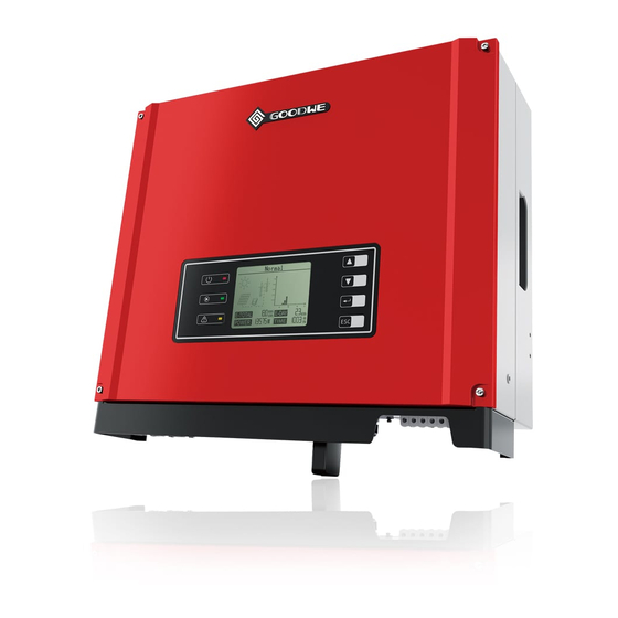
Goodwe Smart DT Series User Manual

Goodwe Smart DT Series User Manual

Solar inverter
Hide thumbs Also See for Smart DT Series:

Advertisement

app
GoodWe(China)
No.189 Kunlunshan Rd.,SND,
Suzhou,215163,China
T: 400 998 1212
service.chn@goodwe.com.cn
www.goodwe.com.cn
GoodWe(Netherlands)
service.nl@goodwe.com.cn
www.goodwe.com.cn
Note: The information above is subject to change without prior notice,details refer to www.goodwe.com.cn.
GoodWe(Australia)
service.au@goodwe.com.cn
www.goodwe.com.cn
GoodWe(UK)
enquiries@goodwe.co.uk
www.goodwe.co.uk
Smart DT SERIES USER MANUAL
SOLAR INVERTER

Advertisement

Table of Contents
loading
Need help?

Need help?

Do you have a question about the Smart DT Series and is the answer not in the manual?

Questions and answers

Summary of Contents for Goodwe Smart DT Series

  • Page 1 Smart DT SERIES USER MANUAL GoodWe(Australia) GoodWe(China) No.189 Kunlunshan Rd.,SND, service.au@goodwe.com.cn Suzhou,215163,China www.goodwe.com.cn T: 400 998 1212 service.chn@goodwe.com.cn www.goodwe.com.cn SOLAR INVERTER GoodWe(Netherlands) GoodWe(UK) enquiries@goodwe.co.uk service.nl@goodwe.com.cn www.goodwe.co.uk www.goodwe.com.cn Note: The information above is subject to change without prior notice,details refer to www.goodwe.com.cn.
  • Page 2: Table Of Contents

    1 Symbols ......................01 2 Safety and Warning ..............01 3 Installation 3.1 Mounting Instruction ......02 3.2 Overview and Packaging ......02 3.3 Inverter Installation ......04 ....... 05 3.4 Electrical Connection 4 System Operation 4.1 LED Lights ..........13 .......
  • Page 3: Symbols

    ●Prohibit inserting or pulling the AC and DC terminals when the inverter is working. ●Only DC connectors provided by GoodWe are permitted to use, otherwise the inverter may be damaged and the warranty will be No more than six (6) identical packages be annulled.
  • Page 4: Inverter Installation

    3.3 Inverter Installation 3.2.1 Inverter Overview 3.3.1 Selecting the Installation Position SDT4~10KW inverter illustration. Installation position should be selected based on the following aspects: ● The installation method and mounting location must be suitable for the inverter's weight and dimensions. 1.
  • Page 5: Electrical Connection

    3.3.2 Mounting Procedure Installation instruction of waterproof coupling series connector please refer to Figure 3.4.1-1. (1) Use the wall-mounted bracket as a template and drill 6 holes on the wall, 10 mm in diameter and 80 mm deep. L1 ----- Live Wire The size of SDT series refer to Figure 3.3.2-1.
  • Page 6: Dc Side Connection

    3.4.1-5. SDT series support four different types of grid. TN-S TN-C TN-C-S Transformer Transformer Transformer Transformer GoodWe GoodWe GoodWe GoodWe DT Series DT Series DT Series DT Series Figure 3.4.1-5 Note:For TT grid structure, RMS voltage between neutral wire and earth wire must be less than 20V.
  • Page 7 3.4.4 Gateway connect The gateway port connects to tigo’s gateway port. Port1 connects to A, Port2 connects to B, Port3 connects to +, Port4 Inverter Positive connector connects to -. Gateway connection please refer to Figure 3.4.4-1. INVERTER Negative connector Figure 3.4.3-1 Note: For installation of Amphenol connectors, These two limit buckles of Amphenol connectors are only for installation positioning use, can’t crimp the wire.
  • Page 8 Lock the sheet metal parts onto the box and tighten the screw cap. Note:1.Meter is non-standard accessories, if the need to use a meter, please contact GOODWE sales manager. 2.Supported DRM command: DRM0, DRM5, DRM6, DRM7, DRM8. 3.Please referto Meter instruction Guide.
  • Page 9: Led Lights

    4 System Operation Error Log Over Utility Date&Time Enter Temperatur Loss 13:29:25 Language 13:12:25 Down Down Histogram 2012-03-25 2012-01-18 Error Log Normal Date&Time Language Error Log Set Time 2012-03-26 Histogram Enter Date&Time Language 13: 12 :25 Down Down Histogram 2012-03-25 Error Log Date&Time Vp1=5500.3V...
  • Page 10 -Histogram Display: Area ③ Normal Error Log Over Utility Enter Temperatur Date&Time Loss 13:29:25 Language 13:12:25 Area③ uses histogram to demonstrate the average power generation at each hour from 4:00am to 8:00pm on one day. Each 2012-03-26 Down Down Histogram 2012-03-25 2012-01-18 columnar points 20 scale, the left top area shows the maximum rated power generation each hour for inverter.
  • Page 11: Error Code

    In all levels of menu, it will automatically enter the first item of the level 1 menu if no action is taken within 305, meanwhile, the Rated', then the output power will be limited to 70%. The function is only for using with VDE AR-N 4105 standard or in France modified data will be stored into internal memory.
  • Page 12: Power Limiting Function Setting

    It is adjustable through special software ,if you want to use it ,ple se contact with after sales. 2.PIug in DC connector, and turn on DC switch. The methods document of using the software can download from goodwe website or contact with after sales. 3.1f voltage is lower than 250V , please check configuration of invert module.
  • Page 13: Technical Parameters

    6 Technical Parameters and Block Diagram GW4000-DT GW5000-DT GW6000-DT GW8000-DT GW9000-DT GW10KN-DT Technical Data Output Over Voltage Protection 6.1 Technical Parameters Operating Temperature Range(℃) -25~60 Technical Data GW4000-DT GW5000-DT GW6000-DT GW8000-DT GW9000-DT GW10KN-DT 0~100% PV String Input Data Operating Altitude(m) ≤4000 Max.DC Input Power(W) 5200...
  • Page 14: Block Diagram

    7.1 Cleaning Level Moisture parameters 4K4H DT series inverter is fitted with two fans on its left side. The fan intakes and handle covers should be cleaned yearly with a vacuum Temperature Range 0~+40℃ -33~+40℃ -20~+55℃ Humidity Range 5%~85% cleaner. For more thorough cleaning, completely remove the fans. 15%~100% 4%~100% Disconnect the AC breaker firstly and then disconnect DC breaker.
  • Page 15 8 Certificates...

This manual is also suitable for:

Gw4000-dtGw9000-dtGw8000-dtGw10kn-dtGw5000-dtGw6000-dt

Table of Contents