Goodwe SMT Series User Manual
Grid-tied pv inverter
Hide thumbs
Also See for SMT Series:
- User manual (64 pages) ,
- Quick installation manual (22 pages) ,
- User manual (44 pages)
Table of Contents
Advertisement
Advertisement
Table of Contents

Related Manuals for Goodwe SMT Series


Summary of Contents for Goodwe SMT Series
- Page 1 User Manual Grid-Tied PV Inverter SMT Series V1.1-2022-09-29...
- Page 2 Copyright ©GoodWe Technologies Co., Ltd., 2022. All rights reserved No part of this manual can be reproduced or transmitted to the public platform in any form or by any means without the prior written authorization of GoodWe Technologies Co., Ltd. Trademarks and other GoodWe trademarks are trademarks of GoodWe Company.
- Page 3 Content User Manual V1.1-2022-09-29 CONTENT...
- Page 4 User Manual V1.1-2022-09-29 Content...
-
Page 5: About This Manual
This manual describes the product information, installation, electrical connection, commissioning, troubleshooting, and maintenance. Read through this manual before installing features, functions, and safety precautions. This manual is subject to update without notice. For www.goodwe.com. 1.1 Applicable Model Model Nominal Output Power... - Page 6 User Manual V1.1-2022-09-29 01 About This Manual DANGER WARNING CAUTION NOTICE 1.4 Updates The latest document contains all the updates made in earlier issues. V1.0 2022-05-31 • First Issue V1.1 2022-09-29 • Chapter 5.1.7.
-
Page 7: Safety Precaution
02 Safety Precaution User Manual V1.1-2022-09-29 2 Safety Precaution Notice and follow all the safety instructions and cautions before any operations. Improper operation 2.1 General Safety Notice • The information in this document is subject to change due to product updates or other reasons. -
Page 8: Inverter Installation
02 Safety Precaution User Manual V1.1-2022-09-29 2.3 AC Side WARNING • • Current. • if you want to use other cables. 2.4 Inverter Installation DANGER • will be damaged. • alter, or damage any label. • Delayed discharge. Wait 5 minutes Disconnect all incoming power are completely discharged. -
Page 9: Product Introduction
03 Product Introduction User Manual V1.1-2022-09-29 3 Product Introduction 3.1 Application Scenarios PV String Circuit Meter Utility combiner Grid 3.2 Circuit Diagram The circuit diagram of GW12KLV-MT, GW15KLV-MT, GW20KLV-MT, GW25K-MT, GW29.9K-MT, GW30K-MT, GW36K-MT is as follows. SWITCH BOOST OUT FILTER AC RELAY MPPT 1+ DC SPD... - Page 10 03 Product Introduction User Manual V1.1-2022-09-29 The circuit diagram of GW60KS-MT and GW35KLS-MT is as follows. SWITCH BOOST MPPT 1+ OUT FILTER MPPT 1- AC RELAY MPPT 2+ DC SPD MPPT 2- MPPT 3+ Filter MPPT 3- Filter Filter MPPT 4+ MPPT 4- MPPT 5+ DC SPD...
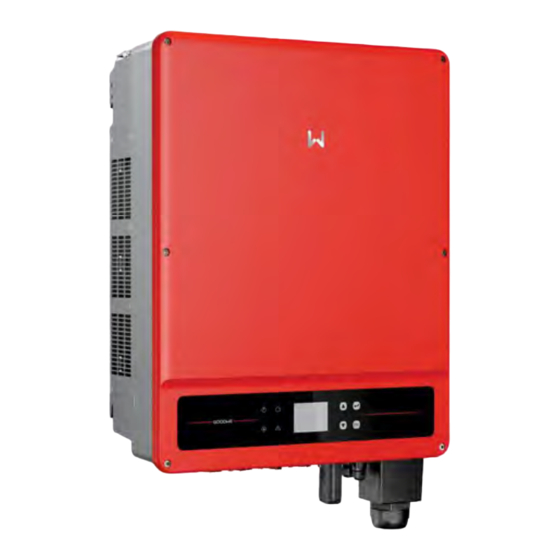
- Page 11 03 Product Introduction User Manual V1.1-2022-09-29 3.4 Appearance reference only. 3.4.1 Parts GW30KLS-MT, GW35KLS-MT, GW12KLV-MT, GW15KLV-MT, GW20KLV- GW50KS-MT, GW60KS-MT MT, GW25K-MT, GW29.9K-MT, GW30K-MT, GW36K-MT Indicator Mounting Plate Handle PV Input PE Terminal DC Switch Terminal Communication Module or Remote Shutdown or...
- Page 12 03 Product Introduction User Manual V1.1-2022-09-29 3.4.2 Dimension GW12KLV-MT, GW15KLV-MT, GW20KLV- GW30KLS-MT, GW35KLS-MT, GW50KS- MT, GW25K-MT, GW29.9K-MT, GW30K-MT, MT, GW60KS-MT GW36K-MT 3.4.3 Indicators Indicator Status Description THE GRID...
- Page 13 03 Product Introduction User Manual V1.1-2022-09-29 3.4.4 Nameplate The nameplate is for reference only. Goodwe trademark, product type, and product model Technical parameters Contact information and serial number Delayed discharge. Wait 5 minutes Disconnect all incoming power are completely discharged.
- Page 14 04 Check and Storage User Manual V1.1-2022-09-29 4 Check and Storage 4.1 Check Before Receiving 1. Check the outer packing box for damage, such as holes, cracks, deformation, and others possible if any damage is found. product and contact the supplier. the supplier as soon as possible if any damage is found.
- Page 15 04 Check and Storage User Manual V1.1-2022-09-29 PV Tool*N 4.3 Storage 1. Do not unpack the outer package or throw the desiccant away. appropriate and no condensation. packing box. put into use.
-
Page 16: Installation Requirements
05 Installation User Manual V1.1-2022-09-29 5 Installation 5.1 Installation Requirements Installation Environment Requirements installation space should be large enough for operations. The temperature and humidity at the installation site should be within the appropriate range. sunshade if it is needed. connections, and checking indicators and labels. - Page 17 User Manual V1.1-2022-09-29 05 Installation Mounting Support Requirements 2. Make sure that the support surface is solid enough to bear the product weight load. generated by the working product, which may annoy the residents nearby. Installation Angle Requirements • • Installation Tool Requirements on site if necessary.
-
Page 18: Moving The Inverter
05 Installation User Manual V1.1-2022-09-29 M3/M5/M 6/M8 Multimeter Cable tie 5.2 Inverter Installation 5.2.1 Moving the Inverter CAUTION 5.2.2 Installing the Inverter NOTICE • • when drilling holes. Step 1 Put the mounting plate on the wall horizontally and mark positions for drilling holes. Step 2 should be 10mm. - Page 19 User Manual V1.1-2022-09-29 05 Installation GW36K-MT. , GW60KS-MT.
-
Page 20: Electrical Connection
06 Electrical Connection User Manual V1.1-2022-09-29 6 Electrical Connection 6.1 Safety Precautions DANGER • may occur. • Perform electrical connections in compliance with local laws and regulations. Including • NOTICE • during electrical connections. • • local laws and regulations. 6.2 Connecting the PE Cable WARNING •... - Page 21 User Manual V1.1-2022-09-29 06 Electrical Connection 6.3 Connecting the PV Input Cable DANGER losses. the permissible range. WARNING • liable for the damage if other connectors are used. • The PV strings cannot be grounded. Ensure the minimum isolation resistance of the •...
- Page 22 06 Electrical Connection User Manual V1.1-2022-09-29 GW25K-MT, GW29.9K-MT, GW30K-MT, Click 1100V GW12KLV-MT, GW15KLV-MT, GW20KLV-MT,...
- Page 23 User Manual V1.1-2022-09-29 06 Electrical Connection Click Click MC4 PV Connectors Connecting the DC Input Cable Step 1 Prepare DC cables. Step 2 Crimp the crimp contacts. Step 3 Disassemble the PV connectors. Step 4 Step 5 Plug the PV connectors into the PV terminals. 4mm²...
- Page 24 06 Electrical Connection User Manual V1.1-2022-09-29 Click Click GW25K-MT, GW29.9K-MT, GW30K-MT, GW36K- 1100V GW12KLV-MT, GW15KLV-MT, GW20KLV-MT, DEVALAN PV Connectors Connecting the DC Input Cable Step 1 Prepare DC cables. Step 2 Crimp the crimp contacts. Step 3 Disassemble the PV connectors. Step 4 Step 5 Plug the PV connectors into the PV terminals.
- Page 25 User Manual V1.1-2022-09-29 06 Electrical Connection Click Click GW25K-MT, GW29.9K-MT, GW30K-MT, GW36K- 1100V GW12KLV-MT, GW15KLV-MT, GW20KLV-MT,...
- Page 26 06 Electrical Connection User Manual V1.1-2022-09-29 6.4 Connecting the AC Output Cable WARNING Inverter model GW12KLV-MT, GW15KLV-MT, GW20KLV-MT, GW25K-MT, GW29.9K-MT, GW30K-MT, GW36K-MT, GW30KLS-MT, GW35KLS-MT GW50KS-MT, GW60KS-MT Inverter model Recommended nominal current of AC breaker GW12KLV-MT GW15KLV-MT GW20KLV-MT GW25K-MT GW29.9K-MT GW30K-MT GW36K-MT GW30KLS-MT GW35KLS-MT...
- Page 27 User Manual V1.1-2022-09-29 06 Electrical Connection WARNING • inappropriately. • the cable core can be exposed. • • an example. • Step 1 Step 2 Step 3 Step 4 GW12KLV-MT, GW15KLV-MT, GW20KLV- MT, GW25K-MT, GW29.9K-MT, GW30K- 90mm 10mm S 25mm 70mm 11mm 22~30mm GW30KLS-MT, GW35KLS-MT, GW50KS-MT,...
-
Page 28: Connecting The Communication Cable
06 Electrical Connection User Manual V1.1-2022-09-29 NOTICE • debris in the maintenance compartment. • 6.5 Communication 6.5.1 Connecting the Communication Cable NOTICE connecting cable should not exceed 1000m. communication from being interfered. Downloads/User%20Manual/GW_Ezlogger%20Pro_User%20Manual-EN.pdf to get the user manual. - Page 29 User Manual V1.1-2022-09-29 06 Electrical Connection RS485 networking scenario Internet EzLogger Pro Router Power limit networking scenario (single inverter) Smart meter Grid Three-phase Meter circuit breaker Power limit networking scenario (multi inverters) Router Cloud SEC1000 Grid Three-phase Meter circuit breaker export power limit control or output power limit control.
- Page 30 06 Electrical Connection User Manual V1.1-2022-09-29 Connecting DRED or RS485 6pin Communication Cable (optional) DRED 6.5mm 25mm DRED RS485 DRED1 DRED2 DRED3 DRED4 REF1 REF2...
- Page 31 User Manual V1.1-2022-09-29 06 Electrical Connection RS485 (5PIN) Cable For Europe and India. Function...
- Page 32 06 Electrical Connection User Manual V1.1-2022-09-29 6.5mm 25mm...
- Page 33 User Manual V1.1-2022-09-29 06 Electrical Connection USB Cable 6.5.2 Installing the Communication Module (optional) and the smartphone or web pages. The communication module can be a WiFi module, or 4G NOTICE • module. •...
- Page 34 06 Electrical Connection User Manual V1.1-2022-09-29 6.5.3 Control the Ethernet communication via the dial switch The terminal resistance of 120ohm...
- Page 35 User Manual V1.1-2022-09-29 07 Equipment Commissioning 7 Equipment Commissioning 7.1 Check Items Before Switching Power ON Check Item operate. correctly and securely. Unused ports and terminals are sealed. 7.2 Power On Step 1 Step 2 Grid DC Isolator The DC switch locking Power ON Power OFF Turn on...
-
Page 36: System Commissioning
08 System Commissioning User Manual V1.1-2022-09-29 8 System Commissioning 8.1 Indicators Indicator Status Description THE GRID 8.2 Setting Inverter Parameters via LCD NOTICE • V1.01.01.01. The screen shots are for • •... -
Page 37: User Interface Introduction
08 System Commissioning User Manual V1.1-2022-09-29 8.2.1 User Interface Introduction communication address. - Page 38 08 System Commissioning User Manual V1.1-2022-09-29 8.2.2 User Interface Introduction The display menu through the Up, Down, Enter, Esc key to operate the menu, which Enter key is the Enter Esc key to toggle the 123 menu, use the up and down keys to select the item and Enter Cancel Down...
- Page 39 08 System Commissioning User Manual V1.1-2022-09-29 Level 1 menu Level 2 menu Level 3 menu Contry Code Contry Code Set Home Hour Select Data Select Data Running Info Configuration Month Select Data History Info Year Select Data Device Info Language Set Language Basic Date&Time...
- Page 40 08 System Commissioning User Manual V1.1-2022-09-29 8.2.4 Basic Settings...
- Page 41 08 System Commissioning User Manual V1.1-2022-09-29...
- Page 42 08 System Commissioning User Manual V1.1-2022-09-29 Advanced Settings...
- Page 43 08 System Commissioning User Manual V1.1-2022-09-29 Power Limit Setting...
- Page 44 08 System Commissioning User Manual V1.1-2022-09-29 History Information The history information mainly includes the information of the generating capacity of the generation, daily power generation, monthly power generation and annual power generation information. Wi-Fi Reset & Wi-Fi Reload...
- Page 45 08 System Commissioning User Manual V1.1-2022-09-29 8.3 Setting Inverter Parameters via App en.goodwe.com/Ftp/EN/Downloads/User%20Manual/GW_SolarGo_User%20Manual-EN.pdf get the user manual. User Manual 8.4 Monitoring via SEMS Portal SEMS Portal is an monitoring platform used to manage organizations/users, add plants, and monitor plant status.
-
Page 46: Maintenance
09 Maintenance User Manual V1.1-2022-09-29 9 Maintenance DANGER • damaged or electric shocks may occur. • Step 1 Step 2 Step 3 9.2 Removing the Inverter WARNING • • Wear proper PPE before any operations. Step 1 communication module, and PE cables. Step 2 Step 3 9.3 Disposing of the Inverter... - Page 47 User Manual V1.1-2022-09-29 09 Maintenance Type of fault Alarm Troubleshooting PV string wiring to the earth. Isolation Failure 1. Disconnect DC switch, check the insulation of PV string wiring to earth. Ground I Failure 2. Reconnect the DC switch again. System Failure 2.
- Page 48 09 Maintenance User Manual V1.1-2022-09-29 Type of fault Alarm Troubleshooting Relay-check Failure DCI High 1. Disconnect the DC connector. 2. Reconnect the DC connector. Failure SPI Failure GFCI Failure 2. Plug in DC connector, and reconnect DC switch. No display Earth Fault Alarm occurs.
-
Page 49: Routine Maintenance
User Manual V1.1-2022-09-29 09 Maintenance 9.5 Routine Maintenance Maintaining Item Maintaining Method Maintaining Period Check the heat sink, air intake, and air System Clean outlet for foreign matter or dust. Check the fan for proper working status, low noise, and intact appearance. DC Switch working properly. -
Page 50: Technical Parameters
10 Technical Parameters User Manual V1.1-2022-09-29 10 Technical Parameters... - Page 51 User Manual V1.1-2022-09-29 10 Technical Parameters Technical Data GW12KLV-MT GW15KLV-MT GW20KLV-MT 60@1.5ms 31.5 39.4 54.3 Max. Total Harmonic Distortion Protection PV String Current Monitoring Integrated PV Insulation Resistance Detection Integrated Residual Current Monitoring Integrated Integrated Integrated Integrated Integrated Integrated DC Switch Integrated DC Surge Protection Remote Shutdown...
- Page 52 10 Technical Parameters User Manual V1.1-2022-09-29 Technical Data GW12KLV-MT GW15KLV-MT GW20KLV-MT User Interface Communication Communication protocols 40.0 Topology Non-isolated Ingress Protection Rating IP65 DC Connector 4K4H Pollution Degree Country of Manufacture China...
- Page 53 User Manual V1.1-2022-09-29 10 Technical Parameters...
- Page 54 10 Technical Parameters User Manual V1.1-2022-09-29 Technical Data GW25K-MT GW29.9K-MT GW30K-MT GW36K-MT 40.0 43.3 53.3 60@1.5ms 36.1 43.2 43.3 52.0 Max. Total Harmonic Distortion Protection PV String Current Monitoring Integrated PV Insulation Resistance Integrated Detection Residual Current Monitoring Integrated Integrated Protection Integrated Integrated...
- Page 55 User Manual V1.1-2022-09-29 10 Technical Parameters Technical Data GW25K-MT GW29.9K-MT GW30K-MT GW36K-MT 0~100% 3000 Cooling Method Smart Fan Cooling User Interface Communication Communication protocols Topology Non-isolated Self-consumption at Night Ingress Protection Rating IP65 DC Connector 4K4H Pollution Degree Country of Manufacture China 30000.
- Page 56 10 Technical Parameters User Manual V1.1-2022-09-29...
- Page 57 User Manual V1.1-2022-09-29 10 Technical Parameters Technical Data GW30KLS-MT GW35KLS-MT GW50KS-MT GW60KS-MT 50@5ms 91.9 72.2 Power Factor Max. Total Harmonic Distortion 97.7% 97.7% Protection PV String Current Monitoring Integrated Internal Humidity Monitoring Integrated PV Insulation Resistance Integrated Detection Residual Current Monitoring Integrated Integrated Integrated...
- Page 58 10 Technical Parameters User Manual V1.1-2022-09-29 Technical Data GW30KLS-MT GW35KLS-MT GW50KS-MT GW60KS-MT 0~100% 3000 Cooling Method Smart Fan Cooling Display Communication Communication protocols 55.0 520 x 660 x 220 Topology Non-isolated Ingress Protection Rating IP65 DC Connector 4K4H Pollution Degree Country of Manufacture China...
- Page 59 User Manual V1.1-2022-09-29 10 Technical Parameters Overvoltage levels: Humidity Levels: Level Environmental Parameters 4K4H Temperature range Humidity range 15% to 100% 4% to 100% Environmental levels: Pollution levels: rain and snow.
- Page 60 GoodWe Website GoodWe Technologies Co., Ltd. www.goodwe.com Local Contacts...
Need help?
Do you have a question about the SMT Series and is the answer not in the manual?
Questions and answers