Table of Contents
Advertisement
MASS 24/15-2, 24/25-2, 24/25-2 DNV, 24/25-2 large cabinet
For the latest version of this manual, visit our website:
EN
Ga om deze handleiding in andere talen te downloaden naar onze website:
NL
Um diese Anleitung in anderen Sprachen herunterzuladen, besuchen Sie bitte unsere Website:
DE
Pour télécharger ce manuel dans d'autres langues, consultez notre site Web :
FR
Para descargar este manual en otros idiomas, visite nuestro sitio web:
ES
Per scaricare questo manuale in altre lingue, visitare la pagina del prodotto sul nostro sito Web:
IT
In case of any discrepancy in the interpretation of different language versions, the English version shall prevail.
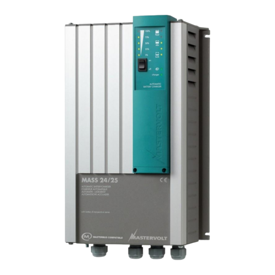
Mass Charger
FULLY AUTOMATIC BATTERY CHARGER
USER AND INSTALLATION MANUAL
www.mastervolt.com
Advertisement
Table of Contents

Related Manuals for Mastervolt Mass Series


Summary of Contents for Mastervolt Mass Series
- Page 1 Para descargar este manual en otros idiomas, visite nuestro sitio web: Per scaricare questo manuale in altre lingue, visitare la pagina del prodotto sul nostro sito Web: www.mastervolt.com In case of any discrepancy in the interpretation of different language versions, the English version shall prevail.
-
Page 2: Table Of Contents
Mass 24/15-2, 24/25-2, 24/25-2 DNV, 24/25-2 (large cabinet) – User and Installation Manual TABLE OF CONTENTS GENERAL INFORMATION .............................. 4 Use of this manual .............................. 4 Validity of this manual ............................4 Use of pictograms .............................. 4 Identification label ............................... 4 Liability ................................ - Page 3 Mass 24/15-2, 24/25-2, 24/25-2 DNV, 24/25-2 (large cabinet) – User and Installation Manual 4.18 Storage and transportation ..........................15 4.19 Re-installation ..............................15 DIP SWITCH SETTINGS ............................... 16 DIP Switch operation ............................16 DIP switch functions ............................16 5.2.1 Force Float (DIP switch 1) ....................... 16 5.2.2 Traction setting (DIP switch 2) ......................
-
Page 4: General Information
Validity of this manual All of the specifications, provisions and instructions contained in this manual apply solely to standard versions of the Mass Charger delivered by Mastervolt. This manual is valid for the following models: Part number Serial number PD05A2002 with device version “A”... -
Page 5: Important Safety Instructions
IMPORTANCE THAT EACH TIME BEFORE USING Use of an attachment or spare part not recommended THE MASS CHARGER, YOU READ THIS MANUAL or sold by Mastervolt may result in a risk of fire, electric AND FOLLOW THE INSTRUCTIONS EXACTLY. shock, or injury to persons. -
Page 6: Warning Regarding Life Support Applications
In addition, the manufacturer must agree to voltages can cause serious damage to batteries. Do indemnify and not hold Mastervolt responsible for any not exceed the recommended limits of discharge level claims arising from the use of the Mass Charger in the life of your batteries. -
Page 7: Operation
See figure 3. On the front of the Mass Charger LED 9 to 13 battery charger/rectifier, developed and produced by represent the charging current. The more LEDs are Mastervolt. The MASS series features a family of advanced illuminated, the higher the charging current. LED 1-5 quality battery chargers. The Mass Charger not only represent the charging state. -
Page 8: Bulk (Led 1 Illuminates)
Mass 24/15-2, 24/25-2, 24/25-2 DNV, 24/25-2 (large cabinet) – User and Installation Manual 3.3.1 Bulk (LED 1 illuminates) battery temperature is high, the charge voltage is The battery is empty when only the first LED Bulk/ON decreased. Over charge and gassing are prevented this illuminates. -
Page 9: Installation
MOUNTING THE MASS CHARGER Mass 24/15-2, 24/25-2, 24/25-2 DNV, 24/25-2 (large cabinet) – User and Installation Manual 4 INSTALLATION CONNECTIONS Wiring During installation and commissioning of the Mass Charger, the important safety instructions are applicable at all times. CAUTION! See chapter 2 of this manual. The wire and fuse sizes stated in this manual are Connection of main given as example only. -
Page 10: Ac Safety Grounding
Never use both methods. Your batteries will be overcharged and severely damaged! Connection of main batteries Pull the cables through the cable glands of the Mass Mastervolt offers several Battery Isolators, refer to Charger. www.mastervolt.com. Crimp on the ring M6 terminals to the cable. -
Page 11: Voltage Sense
Accessories can be plugged in at The battery charger is equipped with a potential free all times. Contact your Mastervolt dealer for an overview of contacts alarm relay, see figure 7. The alarm function has available accessories. -
Page 12: Materials
Mass 24/15-2, 24/25-2, 24/25-2 DNV, 24/25-2 (large cabinet) – User and Installation Manual 4.13 Materials Make sure you have all the parts you need to install the Mass Charger: Product Quantity Mass Charger (included) Battery temperature sensor with cable and plug (included). DC-cable to connect the positive DC connection (+) of the Mass Charger to the positive pole of the DC- distribution;... -
Page 13: Installation Step-By-Step
Mass 24/15-2, 24/25-2, 24/25-2 DNV, 24/25-2 (large cabinet) – User and Installation Manual This schematic is to illustrate the general placement of the Mass Charger in a circuit. It is not meant to provide detailed wiring instructions for any particular electrical installation. AC voltage (V) Figure 8: Installation drawing of the Mass Charger 4.15 Installation step-by-step... -
Page 14: Commissioning After Installation
Mass 24/15-2, 24/25-2, 24/25-2 DNV, 24/25-2 (large cabinet) – User and Installation Manual Option: Connect the Mass Charger to the MasterBus network. Feed the AC wiring through cable gland and connect the wiring to the screw terminals. Tighten the cable gland firmly. Connect the DC-cabling of the house bank, positive to +, negative to –. -
Page 15: Masterbus (Optional)
Always use the original packing for transportation. Contact your local Mastervolt Service Centre for further details if you Some settings can only be changed via the MasterBus want to return the apparatus for repair. -
Page 16: Dip Switch Settings
Via the MasterBus network (by means of a remote control panel or an interface connected to a PC with MasterAdjust software); see chapter 7. Some settings, e.g. Lithium-ion (Mastervolt MLI), can only be changed in this way. Note: Once a DIP switch has been set to On, MasterBus settings are disabled. -
Page 17: Masterbus
Mastervolt also offers several interfaces like the Modbus allowed. and NMEA interface, making even non-MasterBus devices suitable to operate in the MasterBus network. For central monitoring and control of the connected devices Mastervolt offers different remote control panels. -
Page 18: Masterbus Settings
Option to keep MasterBus powered by the battery Disabled Disabled, Enabled when the Mass Charger is disabled. Battery The battery type settings are based on Mastervolt Flooded User defined, batteries. If connecting batteries of a different Gel/AGM, Flooded, manufacturer, make sure the manufacturer's Traction, NiCad, recommendations are met. -
Page 19: Event Based Commands
16.00-32.00 V Equalize time Equalize time 360 min 0-600 min * Depending on model Note: the following charge specifications are based on Mastervolt batteries. Specifications for a given chemistry of a different manufacturer may vary. Battery type Charging specifications Traction NiCad... - Page 20 Mass 24/15-2, 24/25-2, 24/25-2 DNV, 24/25-2 (large cabinet) – User and Installation Manual Figure 10 shows the meaning of the event data. Input (pulses) The input is represented by an on/off switch. Output (data) On changes the status to On at the first signal. Off changes the status to Off at the first signal.
-
Page 21: Trouble Shooting
In case of a failure, the Mass Charger display shows an error code to help you find its source. See section 3.3 for error codes. If you cannot solve a problem with the aid of the fault-finding table, contact your local Mastervolt Service Centre. See www.mastervolt.com. -
Page 22: Technical Data
1 x 25 A and 1x3 A Charge characteristic* 3-step, fully automatic 3-step, fully automatic 3-step, fully automatic Battery types*: Flooded lead acid, gel/AGM lead acid, NiCd, Mastervolt Lithium-ion (Mastervolt MLI) (see chapter 7 for settings) Default charge voltages at 25°C: absorption 28.5V 28.5V 28.5V... -
Page 23: Dimensions
Mass 24/15-2, 24/25-2, 24/25-2 DNV, 24/25-2 (large cabinet) – User and Installation Manual Dimensions Figure 11: Dimensions of C1 enclosure in mm [inch] DNV and large cabinet version lengths are underlined... -
Page 24: Characteristics (230 V Ac)
Mass 24/15-2, 24/25-2, 24/25-2 DNV, 24/25-2 (large cabinet) – User and Installation Manual Characteristics (230 V AC) Charge current vs input voltage Figure 12: Charge current versus input voltage... - Page 25 Mass 24/15-2, 24/25-2, 24/25-2 DNV, 24/25-2 (large cabinet) – User and Installation Manual Figure 13: Charge characteristic of the three-step Plus charging method (at 25°C / 77°F) For a 24V charger, multiply the voltages by two.
- Page 26 Mass 24/15-2, 24/25-2, 24/25-2 DNV, 24/25-2 (large cabinet) – User and Installation Manual Figure 14: Charge characteristic of the equalize charge cycle (at 25°C / 77°F)
- Page 27 Mass 24/15-2, 24/25-2, 24/25-2 DNV, 24/25-2 (large cabinet) – User and Installation Manual Figure 15: Temperature compensation characteristic (charge voltage versus temperature)
- Page 28 Technical Support T: +31 (0) 20 34 22 100 T: +1 262 293 0600 / 800 307 6702 T: +64 9 415 7261 E: ts.emea@OneASG.com E: tech.mastervolt@OneASG.com E: technical.apac@OneASG.com Location & Shipping Location & Shipping Location & Shipping Navico Group EMEA...
Need help?
Do you have a question about the Mass Series and is the answer not in the manual?
Questions and answers