Table of Contents
Advertisement
Quick Links
USERS MANUAL / GEBRUIKERSHANDLEIDING / BETRIEBSANLEITUNG
MANUEL UTILISATEUR / MANUAL DE UTILIZACION / INSTRUZIONI PER L'USO
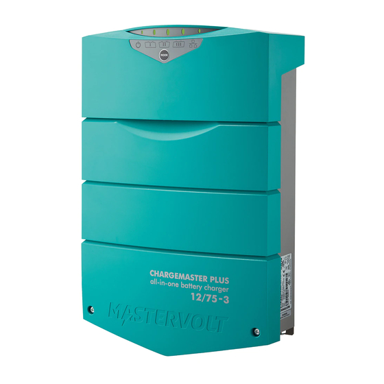
CHARGEMASTER PLUS
MASTERVOLT
Snijdersbergweg 93,
1105 AN Amsterdam
The Netherlands
Tel.: +31-20-3422100
Fax.: +31-20-6971006
www.mastervolt.com
12/75-3, 12/100-3, 24/40-3, 24/60-3
FULLY AUTOMATIC BATTERY CHARGER
Copyright © 2017 Mastervolt, 10000011898/09
ENGLISH
NEDERLANDS:
DEUTSCH:
FRANÇAIS:
CASTELLANO:
ITALIANO:
See www.mastervolt.com/chargemaster
Siehe www.mastervolt.com/chargemaster
Voir www.mastervolt.com/chargemaster
Vea www.mastervolt.com/chargemaster
Vedere www.mastervolt.com/chargemaster
Advertisement
Table of Contents

Related Manuals for Mastervolt chargemaster plus 12/75-3


Summary of Contents for Mastervolt chargemaster plus 12/75-3
- Page 1 USERS MANUAL / GEBRUIKERSHANDLEIDING / BETRIEBSANLEITUNG MANUEL UTILISATEUR / MANUAL DE UTILIZACION / INSTRUZIONI PER L’USO CHARGEMASTER PLUS 12/75-3, 12/100-3, 24/40-3, 24/60-3 FULLY AUTOMATIC BATTERY CHARGER Copyright © 2017 Mastervolt, 10000011898/09 ENGLISH MASTERVOLT NEDERLANDS: See www.mastervolt.com/chargemaster Snijdersbergweg 93, DEUTSCH: Siehe www.mastervolt.com/chargemaster 1105 AN Amsterdam FRANÇAIS:...
-
Page 2: Table Of Contents
TABLE OF CONTENTS: 1 GENERAL INFORMATION 1.1 U SE OF THIS MANUAL 1.2 V ALIDITY OF THIS MANUAL 1.3 U SE OF PICTOGRAMS 1.4 I DENTIFICATION LABEL 1.5 L IABILITY 2 IMPORTANT SAFETY INSTRUCTIONS 2.1 G ENERAL 2.2 E XPLOSIVE GASES 2.3 PERSONAL PRECAUTIONS 2.4 W ARNINGS REGARDING THE USE OF BATTERIES... - Page 3 4 INSTALLATION 4.1 U NPACKING 4.2 E NVIRONMENT 4.3 W IRING 4.3.1 DC WIRING 4.3.2 AC- WIRING 4.3.3 AC SAFETY GROUNDING 4.4 B ATTERIES 4.5 T HINGS YOU NEED 4.6 O VERVIEW CONNECTION COMPARTMENT 4.7 C ONNECTION 4.7.1 G ENERAL 4.7.2 C ONNECTION EXAMPLE 4.8 I...
-
Page 4: General Information
Important Safety Instructions. Copyright © 2017 Mastervolt. All rights reserved. Reproduction, transfer, distribution or storage of part or all of the contents in this document in any form without the... -
Page 5: Important Safety Instructions
Regulations (33CFR183, Sub part I). overheating may result. Use of an attachment or spare part not recommended EXPLOSIVE GASES or sold by Mastervolt may result in a risk of fire, – electric shock, or injury to persons. WARNING RISK EXPLOSIVE GASES. -
Page 6: Personal Precautions
PERSONAL PRECAUTIONS Never place charger directly above battery being charged; gases from battery will corrode and damage Consider having someone close enough by to come charger. to your aid when you work near a lead-acid battery. Never allow battery acid to drip on charger when Have plenty of fresh water and soap nearby in case reading electrolyte specific gravity or filling battery. -
Page 7: Follow These Steps When Battery Is Outside Vehicle
In addition the manufacturer (BLACK) charger clip to free end of cable. must agree to indemnify and not hold Mastervolt Do not face battery when making final connection. responsible for any claims arising from the use of the When disconnecting charger, always do so in reverse ChargeMaster Plus in the life support equipment. -
Page 8: Operating Instructions
3 OPERATING INSTRUCTIONS FEATURES The three-step Plus charging method guarantees that the batteries are always charged to 100%. The Mastervolt ChargeMaster Plus is a fully automatic See section 3.4 battery charger. This means that under normal circumstances it may stay switched on with the AC power Global Charging and batteries connected. -
Page 9: Local User Interface
LOCAL USER INTERFACE By holding the MODE switch pressed again for approx. 3 The status display at the front side of the ChargeMaster seconds, the ChargeMaster Plus will switch back to stand- Plus enables you to control the charger and monitor the by: the ChargeMaster Plus stops and the MODE LED charging process. -
Page 10: Status-Display
STATUS-DISPLAY Menu MODE LED color Meaning The status display has a 3 level menu. Menu navigation is Level 1 Green Status menu done by shortly pressing the MODE switch. After each Level 2 Orange Output power menu press the next menu level is shown. The MODE LED color Level 3 Error menu indicates the level that is being shown. -
Page 11: Three Step Plus Charge Algorithm
THREE STEP PLUS CHARGE ALGORITHM stage, the charge voltage is lower than in absorption stage. Pre-float ensures batteries that are nearly full don’t See Figure 3. Battery charging is accomplished in three receive the higher charge voltage needed in the automatic stages: BULK, ABSORPTION and FLOAT. -
Page 12: Smart Terminal - Output
SMART TERMINAL - OUTPUT 3 alternator can also be used to charge battery 1 & 2. The threshold voltage which is used to switch over is The Chargemaster is equipped with three full outputs. The configured via MasterBus. See section 5.2 total output current is divided over these three outputs. -
Page 13: Installation
4 INSTALLATION During installation commissioning No objects must be located within a distance of 10 cm / ChargeMaster Plus, the important safety instructions are 4 inch around the ChargeMaster Plus. applicable at all times. Do not locate the ChargeMaster Plus in the same compartment as the batteries. -
Page 14: Ac-Wiring
For safe installation it is necessary to insert a Residual Current Device (earth leakage The fuse with the fuse-holder is available from your local Mastervolt distributor or Customer Service Representative. switch) in the AC input circuit of the ChargeMaster Plus. -
Page 15: Overview Connection Compartment
Socket wrench 10mm to fix the Safety ground Tools to fix the screws / bolts (Ø 6mm) with plugs to connection mount the enclosure to a surface Flat blade screw driver 1.0 x 4.0 mm to fix the screw Philips screw driver nr. -
Page 16: Connection
CONNECTION CAUTION! 4.7.1 General Too-thin cables and/or loose connections can cause dangerous overheating of the cables WARNING and/or terminals. Therefore tighten Let installation work be done by a licensed connections well, in order to limit transition electrician. resistance as far as possible. Use cables of All electrical systems (AC and DC) must be the correct size. -
Page 17: Connection Example
4.7.2 Connection example This schematic is to illustrate the general placement of the Chargemaster Plus in a circuit. It is not meant to provide detailed wiring instructions for any particular electrical installation. Figure 6: installation drawing of the ChargeMaster Plus... -
Page 18: Installation Step-By-Step
INSTALLATION STEP-BY-STEP Fix the enclosure to the wall by fastening two screws at the lower side of the enclosure as well. Mark the position of the mounting spots by using the mounting bracket. Then Fix the mounting bracket to the wall. Connect the wiring to the screw terminals. -
Page 19: Commissioning After Installation
Check all wiring; see also figure 6 for wiring Attach the battery temperature sensor to the details. casing of battery bank 1. Plug the temperature sensor cable into the “temp.sensor” jack. Close the connection compartment by fixing the four screws. Continue with section 4.9 for commissioning Option: Connect the ChargeMaster to the of the ChargeMaster. -
Page 20: Masterbus (Optional)
Always use the original packing for transportation. Contact interface. See section 5.2 for an overview of all available your local Mastervolt Service Centre for further details if MasterBus settings. Refer to the user’s manual of the you want to return the apparatus for repair. -
Page 21: Settings
5 SETTINGS MASTERBUS FUNCTIONS Adjustment of the settings of the ChargeMaster Plus can be made in two different ways: Adjustment of the settings of the ChargeMaster Plus can By means of DIP-switches; see section 5.1; be made via the MasterBus network (by means of a ... -
Page 22: Li-Ion Battery Mli Ultra
5.2.4 Li-ion Battery MLi Ultra 5.2.5 In use If not all outputs of the ChargeMaster Plus are used, the The ChargeMaster Plus is compatible to be used with a Li- unused outputs can be excluded from sending alarm ion battery MLi Ultra. Refer to the manual of the Li-ion messages. -
Page 23: History
Value Meaning Adjustable range Output 2 Battery high DC output voltage is too high (read only) Battery low DC output voltage is too low (read only) DC + and DC –are connected in reverse (this will damage the charger) Reverse polarity (read only) Smart terminal Battery high... - Page 24 Value Meaning Factory setting Adjustable. Range Temp. Temperature depended charge voltage compensation -0,030V/°C/ -1,000/+1,000V/°C compensate -0,060V/°C Smart terminal Smart terminal operation mode 10A Starter Starter, Starter + alternator, Follow main, Follow main + alternator, 12V constant voltage, 24V constant voltage*, 12V 3-step +* Maximum current Smart terminal maximum DC input/output current...
-
Page 25: Events
5.2.10 Events Figure 8: Meaning of the event data. Input (pulses) The input is represented by an on/off switch. Output (data) On changes the status to On at the first signal. Off changes the status to Off at the first signal. Copy lets the status follow the input. -
Page 26: Event Target
5.2.12 Event target The ChargeMaster Plus can be configured as an event target by other devices on the MasterBus network. When the ChargeMaster Plus is configured as an event target by another device, this device can initiate an event command and an event action to be performed by the ChargeMaster Plus. -
Page 27: Trouble Shooting
6 TROUBLE SHOOTING If you cannot solve a problem with the aid of this chapter, contact your local Mastervolt Service Centre. See www.mastervolt.com. Make sure you have the following information present if you have to contact your local Mastervolt Service Center to solve a problem: ... -
Page 28: Technical Data
7 TECHNICAL DATA SPECIFICATIONS 12V MODELS Model 12/75-3 12/100-3 Article no. 44310750 44311000 GENERAL Nominal input voltage*: 120/230V 120/230V Nominal input frequency: 50/60Hz 50/60Hz Full load consumption: 1300VA 1700VA Max. AC input current (@ 230VAC) Max. AC input current (@ 120VAC) Nominal output voltage: Total charge current*: 75A at 14.4V... -
Page 29: Specifications 24V Models
SPECIFICATIONS 24V MODELS Model 24/40-3 24/60-3 Article no. 44320400 44320600 GENERAL Nominal input voltage*: 120/230V 120/230V Nominal input frequency: 50/60Hz 50/60Hz Full load consumption 1400VA 2000VA Max. AC input current (@ 230VAC) Max. AC input current (@ 120VAC) Nominal output voltage: Total charge current*: 40A at 28.8V 60A at 28.8V... -
Page 30: Dimensions
DIMENSIONS Dimensions in mm ChargeMaster Plus models 12/75-3, 12/100-3, 24/40-3 and 24/60-3... -
Page 31: Ordering Information
* standard included with the delivery of the ChargeMaster Plus Mastervolt can offer a wide range of products for your electrical installation, including an extended program of components for your MasterBus network, both AGM and gel batteries, shore power connections, DC distribution kits and many more See our website www.mastervolt.com for an extensive overview of all our products...
Need help?
Do you have a question about the chargemaster plus 12/75-3 and is the answer not in the manual?
Questions and answers