Table of Contents
Advertisement
USERS MANUAL / GEBRUIKERSHANDLEIDING / BETRIEBSANLEITUNG
MANUEL UTILISATEUR / MANUAL DE UTILIZACION / INSTRUZIONI PER L'USO
CHARGEMASTER 1
12/35-3, 12/50-3, 24/20-3, 24/30-3
MASTERVOLT
Snijdersbergweg 93,
1105 AN Amsterdam
The Netherlands
Tel.: +31-20-3422100
Fax.: +31-20-6971006
www.mastervolt.com
FULL AUTOMATIC BATTERY CHARGER
ENGLISH:
NEDERLANDS:
DEUTSCH:
FRANÇAIS:
CASTELLANO:
ITALIANO:
Copyright © 2009 Mastervolt v1.3 August 2009
PAGE 1
PAGINA 29
SEITE 57
PAGINA 85
PÁGINA 113
PÁGINA 141
Advertisement
Table of Contents

Related Manuals for Mastervolt ChargeMaster 12/35-3


Summary of Contents for Mastervolt ChargeMaster 12/35-3
- Page 1 FULL AUTOMATIC BATTERY CHARGER ENGLISH: PAGE 1 MASTERVOLT NEDERLANDS: PAGINA 29 Snijdersbergweg 93, DEUTSCH: SEITE 57 1105 AN Amsterdam FRANÇAIS: PAGINA 85 The Netherlands CASTELLANO: PÁGINA 113 Tel.: +31-20-3422100 ITALIANO: PÁGINA 141 Fax.: +31-20-6971006 www.mastervolt.com Copyright © 2009 Mastervolt v1.3 August 2009...
-
Page 2: Table Of Contents
CONTENTS CONTENTS: v 1.3 August 2009 GENERAL INFORMATION.............................. 4 Use of this manual.............................. 4 Validity of this manual ............................4 Use of pictograms .............................. 4 Identification label............................... 4 Liability ................................4 IMPORTANT SAFETY INSTRUCTIONS ......................... 5 General ................................5 Explosive gases ..............................5 Warnings regarding the use of batteries...................... - Page 3 CONTENTS MASTERBUS................................. 16 What is MasterBus? ............................16 How to set up a MasterBus network......................... 17 MasterBus: Monitoring and Programming of the ChargeMaster............... 18 6.3.1 Monitoring............................18 6.3.2 Alarms ............................. 18 6.3.3 History ............................. 18 6.3.4 Configuration ........................... 19 6.3.5 ChargeMaster 1 event source list (ChargeMaster as event source)..........
-
Page 4: General Information
The English version has 28 pages. IP 23 Part no : 44020300 Type : ChargeMaster 24/30-3 Copyright © 2009 Mastervolt. All rights reserved. Input : 120/230V AC 50/60 Hz 8.5A/4.2A Reproduction, transfer, distribution or storage of part or all Output : 28.5VDC- 30A... -
Page 5: Important Safety Instructions
Chargemaster in a non-ventilated room, overheating Regulations (33CFR183, Sub part I). may result. Use of an attachment or spare part not recommended EXPLOSIVE GASES or sold by Mastervolt may result in a risk of fire, electric shock, or injury to persons. WARNING – RISK EXPLOSIVE GASES. -
Page 6: Warnings Regarding The Use Of Batteries
It might manufacturing process. In addition the manufacturer must spark or short-circuit battery or other electrical part agree to indemnify and not hold Mastervolt responsible for that may cause explosion. any claims arising from the use of the Chargemaster in the Remove personal metal items such as rings, life support equipment. -
Page 7: Operation
FEATURES Once switched ChargeMaster The Mastervolt Chargemaster is a fully automatic battery automatically resumes operation after it was charger. This means that under normal circumstances it disconnected from an AC-source temporarily. may stay switched on with the AC power and batteries connected. -
Page 8: Display
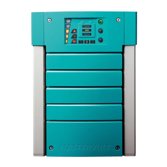
OPERATION DISPLAY The Chargemaster is equipped with a multicolour LED with the load bar shows the percentage of maximum display. Different LED colours and combinations have current, of the three Battery banks together. different meanings. Combination of the current display (A) Combination of (V) with the load bar shows the actual charging voltage. -
Page 9: Temperature Compensated Charging
13.25V (12V models) or 26.5V (24V models) at 25°C / communication between the different Mastervolt system 77°F and stabilises this voltage to maintain the batteries in devices such as the inverter, battery charger, generator, an optimum condition. Connected DC-loads are powered batteries and many more. -
Page 10: Installation
INSTALLATION 4 INSTALLATION During installation commissioning 4.3.1 AC wiring Chargemaster, the important safety instructions are For a safe installation the correct wire cross section must applicable at all times. See chapter 2 of this manual. be applied. Don’t use a cross section that is smaller than indicated. -
Page 11: Battery Capacity
The ground wire offers protection only if the The fuse with the fuse-holder is available from your local cabinet of the Chargemaster is connected to Mastervolt distributor or Customer Service Representative, the safety ground. Connect the ground see chapter 9 Ordering information. -
Page 12: Things You Need
INSTALLATION THINGS YOU NEED Make sure you have all the parts you need to install the Chargemaster: Quantity Chargemaster (included) Battery temperature sensor with cable and plug (included). DC cable to connect the positive DC connection (+) of the Chargemaster to the positive pole of the DC- distribution;... -
Page 13: Connection Example
INSTALLATION 4.6.1 Connection example AC Input DC fuse Battery fuse Battery Battery fuse fuse Temperature sensor BATTERY BATTERY BATTERY BANK 1 BANK 2 BANK 3 This schematic is to illustrate the general placement of the Chargemaster in a circuit. It is not meant to provide detailed wiring instructions for any particular electrical installation. -
Page 14: Installation Step By Step
Always use the original packing for transportation. Contact in places with insufficient ventilation, due to your local Mastervolt Service Centre for further details if the gassing of the batteries an explosion can you want to return the apparatus for repair. -
Page 15: Settings
SETTINGS 5 SETTINGS Adjustment of the settings of the ChargeMaster can be 5.1.3 DIP-switch 3: Stand-by mode for display made in two different ways: • By means of DIP-switches; see section 5.1; Display will switch off when Chargemaster is • Via the MasterBus network (by means of a remote switched to stand-by mode (factory setting) control panel or an interface connected to a PC with... -
Page 16: Masterbus
This enables For direct communication between the MasterBus network communication between the connected devices, for and a product which is not from Mastervolt, the Modbus instance to start the generator when the batteries are low. interface is recommended. -
Page 17: How To Set Up Amasterbus Network
Keep the following rules in mind: allowed. Connections between the devices are made by standard straight UTP patch cables. Mastervolt can supply these cables. These cables are also commonly available at computer supply stores. Figure 10... -
Page 18: Masterbus: Monitoring And Programming Of The Chargemaster
MASTERBUS MASTERBUS: MONITORING AND PROGRAMMING OF THE CHARGEMASTER 6.3.1 Monitoring Value Meaning State Shows charger state (Charging/ Stand by) Max input power Option to set the maximum current at the input to prevent generator or shore fuse overload Charger status State of charge algorithm: Bulk/ absorption/ float House bank Voltage of charger output 1*... -
Page 19: Configuration
MASTERBUS 6.3.4 Configuration Below parameters can be changed via the MasterBus network by means of a remote control panel or by means of an interface connected to a PC with MasterAdjust software. See applicable user’s manuals for details. Value Meaning Factory setting Adjustable. -
Page 20: Chargemaster 1 Event Source List (Chargemaster As Event Source)
MASTERBUS Value Meaning Factory setting Adjustable. range Equalize mode Equalize is suitable FOR WET BATTERIES ONLY!. Off, On** Off=no, On=yes Events Event x source Event by the ChargeMaster that should result in an Disabled See section 6.3.5 Event action by one of the other devices on the MasterBus source list network. -
Page 21: Trouble Shooting
TROUBLE SHOOTING 7 TROUBLE SHOOTING If you cannot solve a problem with the aid of this chapter, contact your local Mastervolt Service Centre. See www.mastervolt.com. Make sure you have the following information present if you have to contact your local Mastervolt Service Center to solve a problem: Article and serial number (See section 1.4) -
Page 22: Technical Data
TECHNICAL DATA 8 TECHNICAL DATA SPECIFICATIONS 12V MODELS Model 12/35-3 12/50-3 Article no. 44010350 44010500 GENERAL Nominal input voltage: 120/230V 120/230V Nominal input frequency: 50/60Hz 50/60Hz Full load consumption: 575VA 825VA Efficiency at full load (230V AC): ≥81% @ 230V input ≥81% @ 230V input Nominal output voltage: Total maximum charge current*:... -
Page 23: Specifications 24V Models
TECHNICAL DATA SPECIFICATIONS 24V MODELS Model 24/20-3 24/30-3 Article no. 44020200 44020300 GENERAL Nominal input voltage: 120/230V 120/230V Nominal input frequency: 50/60Hz 50/60Hz Full load consumption: 660VA 925VA Efficiency at full load: ≥83% @ 120V input ≥85% @ 230V input Nominal output voltage: Total maximum charge current*: 20A at 28.8V... -
Page 24: Dimensions
TECHNICAL DATA DIMENSIONS Figure 14: Dimensions in mm (inch) August 2009 / Chargemaster1 12/35-3, 12/50-3, 24/20-3 & 24/30-3 / EN... -
Page 25: Characteristics
TECHNICAL DATA CHARACTERISTICS Figure 15: Charge current versus input voltage BULK ABSORPTION FLOAT BULK `min. bulk timer: `min. abs timer: 2 min 15 min Bulk 14.40VDC Absorption 14.25VDC 13.25VDC Start max bulk timer: 13.25VDC Float 12.80VDC Return to bulk: 12.80VDC Imax 100% Imax <... - Page 26 TECHNICAL DATA FLOAT EQUALIZE FLOAT Float voltage + 2.25V = 15.50VDC Float voltage = 13.25VDC 10% of Imax Max equalize time = 6hr = voltage Start equalize cycle by jumper change (disabled when Gel) = current Figure 17: Charge characteristic of the equalize charge cycle (see section 5.1.3) (at 25°C / 77°F) Figure 18: Temperature compensation characteristic (charge voltage versus temperature) August 2009 / Chargemaster1 12/35-3, 12/50-3, 24/20-3 &...
-
Page 27: Ordering Information
* standard included with the delivery of the Chargemaster Mastervolt can offer a wide range of products for your electrical installation, including an extended program of components for your MasterBus network, both AGM and gel batteries, shore power connections, DC distribution kits and many more. -
Page 28: Ec Declaration Of Conformity
Manufacturer Mastervolt Address Snijdersbergweg 93 1105 AN Amsterdam The Netherlands Herewith declares that: Product: Chargemaster 12/35-3 44010350 Chargemaster 12/50-3 44010500 Chargemaster 24/20-3 44020200 Chargemaster 24/30-3 44020300 Is in conformity with the provision of the EC, EMC directive 89/336/EEC and amendments 92/31/EEC, 93/68/EEC.
Need help?
Do you have a question about the ChargeMaster 12/35-3 and is the answer not in the manual?
Questions and answers