Table of Contents
Advertisement
USERS MANUAL / GEBRUIKERSHANDLEIDING / BETRIEBSANLEITUNG
MANUEL UTILISATEUR / MANUAL DE UTILIZACION / INSTRUZIONI PER L'USO
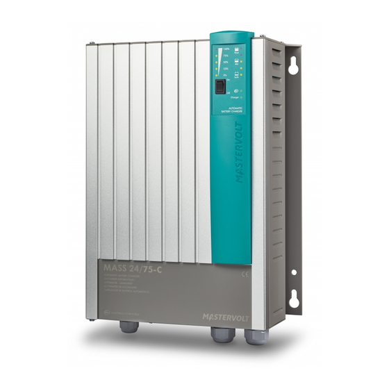
MASS 12/60-2; 12/80-2; 24/50-2; 24/75-C;
24/100-C; 3-24/100 ; 48/25 ; 48/50
MASTERVOLT
Snijdersbergweg 93,
1105 AN Amsterdam
The Netherlands
Tel.: +31-20-3422100
Fax.: +31-20-6971006
www.mastervolt.com
Mass Charger
FULL AUTOMATIC BATTERY CHARGER
ENGLISH:
NEDERLANDS:
DEUTSCH:
FRANÇAIS:
CASTELLANO:
ITALIANO:
Copyright © 2010 Mastervolt, v 2.2 July 2010
PAGE 1
PAGINA 29
SEITE 57
PAGINA 85
PÁGINA 113
PÁGINA 141
Advertisement
Table of Contents


Need help?
Do you have a question about the MASS 12/80-2 and is the answer not in the manual?
Questions and answers