Table of Contents
Advertisement
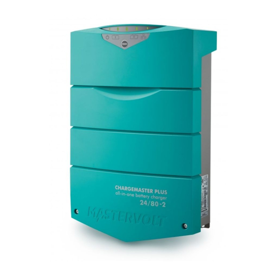
CHARGEMASTER PLUS
For the latest version of this manual, visit our website:
EN
Ga om deze handleiding in andere talen te downloaden naar onze website:
NL
Um diese Anleitung in anderen Sprachen herunterzuladen, besuchen Sie bitte unsere Website:
DE
Pour télécharger ce manuel dans d'autres langues, consultez notre site Web :
FR
Para descargar este manual en otros idiomas, visite nuestro sitio web:
ES
Per scaricare questo manuale in altre lingue, visitare la pagina del prodotto sul nostro sito Web:
IT
24/80-2, 24/110-2
AUTOMATIC BATTERY CHARGER
USER AND INSTALLATION MANUAL
10000015468/06
www.mastervolt.com
Advertisement
Table of Contents


Need help?
Do you have a question about the CHARGEMASTER PLUS 24/80-2 and is the answer not in the manual?
Questions and answers
all lights blink orange, and charger does not charge. Green lights not lit
When all lights blink orange on a Mastervolt 24/80-2 charger and the green lights are not lit, it indicates that there is no output voltage or current, and no AC input is detected. This suggests a problem with the AC input, such as disconnected wiring, low voltage, or an inactive generator.
This answer is automatically generated