Table of Contents
Advertisement
Advertisement
Table of Contents

Related Manuals for Keysight 34980A


Summary of Contents for Keysight 34980A
- Page 1 Keysight 34980A Multifunction Switch/ Measure Unit Getting Started Guide...
- Page 2 WARRANTIES OF MERCHANTABILITY AND Keysight Technologies as governed by Accordingly, Keysight provides the FITNESS FOR A PARTICULAR PURPOSE. United States and international KEYSIGHT SHALL NOT BE LIABLE FOR Software to U.S. government copyright laws. ERRORS OR FOR INCIDENTAL OR customers under its standard...
-
Page 3: Safety Symbols
This document contains references to Agilent. Please note that Agilent’s Test NOTE and Measurement business has become Keysight Technologies. For more information, go to www.keysight.com. Safety Symbols The following symbols or markings that may be on or with the instrument and in the documentation indicate precautions which must be taken to maintain safe operation of the instrument. -
Page 4: Additional Safety Notices
Keysight Technologies assumes no liability of the customer’s failure to comply with the requirements. Refer to the User Guides of the 34980A and relevant modules before using WARNING the equipment. - Page 5 WARNING or death may remain even after external circuits have been disconnected. To avoid electrical shock, remove the main power cord from the 34980A and ensure all connections to the DUT, including field wiring to the instrument and the analog bus (if present) are deenergized and all circuits are discharged before coming in contact with the system.
- Page 6 – Install the signal generators so that one of the following items is readily identifiable and easily reached by the operator: AC power cord, alternative switch or circuit breaker. – Insert the mains plug into a socket outlet provided with a protective earth grounding. Keysight 34980A Getting Started Guide...
- Page 7 No operator serviceable parts inside. Do not install substitute parts or perform any unauthorized modifications to the instrument. Return the instrument to Keysight for service and repair to ensure the safety features are maintained in operational condition. Instruments that appear damaged or defective should be made inoperative and secured against unintended operation until they can be repaired.
-
Page 8: Environmental Conditions
Environmental Conditions Keysight 34980A is designed for indoor use in an installation category II and low condensation environment. Table below shows the general environmental conditions for this instrument. Refer to the product data sheet at https://literature.cdn.keysight.com/litweb/pdf/5989-1437EN.pdf for more information on the instrument general specifications. -
Page 9: Regulatory Markings
European Legal Standards Association. Directives. The UK conformity mark is a UK The Keysight email address is required government owned mark. Products by EU directives applicable to our showing this mark comply with all product. - Page 10 This mark indicates product has been designed to meet the requirements of Universal recycling symbol. "IP x y", where "x" is the solid particle protection and "y" is the liquid ingress protection. Keysight 34980A Getting Started Guide...
-
Page 11: Waste Electrical And Electronic Equipment (Weee) Directive 2002/96/ Ec
Trade in options with Keysight in addition to product takeback instructions. Sales and Technical Support To contact Keysight for sales and technical support, refer to the support links on the following Keysight websites: – www.keysight.com/find/34980a (product-specific information and support, software and documentation updates) –... - Page 12 THIS PAGE HAS BEEN INTENTIONALLY LEFT BLANK. Keysight 34980A Getting Started Guide...
-
Page 13: Table Of Contents
Menu Example: Configuring a Channel for a Measurement ..40 Connecting the 34980A to Your Computer ..... .46 Connecting Over LAN . - Page 14 ......54 Exploring the 34980A Web Interface Over LAN ....55 Launching the Web Interface .
- Page 15 Exploring the 34980A Web Interface Over LAN 34980A Documentation Map This guide provides an overview of the 34980A’s controls, displays and connections; module assembly, wiring and installation instructions; and some basics of operation with examples. It is designed to allow you to gain quick...
-
Page 16: Getting Started
– Small flatblade screwdriver to connect field wiring to optional terminal blocks – Keysight E2094 IO Libraries Suite Any plug-in modules that you ordered will be shipped separately from the 34980A mainframe. If you ordered optional terminal blocks or cables with your modules, they will be included in the shipment with your modules. -
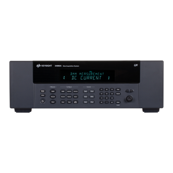
Page 17: Front Panel At A Glance
Control Keys. Provide access to immediate execute actions such as closing and opening channels. Number Keypad. Allows you to enter numeric values such as channel numbers. Exponent Key. Allows you to enter exponential values (e.g., 10E3). Keysight 34980A Getting Started Guide... - Page 18 Configure Key Group. Select functions and set various measurement parameters on the selected channel. Measure Key Group. Execute and monitor measurements. Depending on which measurement key you select, you can have complete/direct control over the switching and measurement operations, or you can let the 34980A automatically control the switching and measurement.
-
Page 19: Rear Panel At A Glance
Caution. Refer to accompanying descriptions in User’s Guide Alternating Current Mainframe Chassis Ground Access to Analog Buses (shown with removable cover installed). See 34980A User’s Guide for connector pinout. Module shown installed in Slot 1 Keysight 34980A Getting Started Guide... - Page 20 AC Power Connector LAN Connector (10Base T/100Base Tx) USB 2.0 Connector External Trigger/Alarm/Digital I/O Connector. See 34980A User’s Guide for connector pinout. Internal DMM Option Marking. If you ordered the internal DMM option, this circle is marked black. IEEE 488.2 GPIB Connector...
-
Page 21: Removing A Slot Cover
Getting Started Removing a Slot Cover Your 34980A is shipped from the factory with one slot uncovered and the remaining seven slots covered. When performing tasks in this guide to become familiar with the instrument, you will install a plug-in module into Slot 1. When you are ready to install additional modules, follow the procedure below to remove a slot cover. - Page 22 Getting Started For proper module cooling, all unused slots must be covered. CAUTION Do not block air intake or exhaust vents at the sides of the instrument. CAUTION Keysight 34980A Getting Started Guide...
-
Page 23: Installing A Module
If the proper connections are not present, the Analog Bus relays will be disabled on that module and the front panel “Safety Interlock” display annunciator will turn on. See the 34980A User’s Guide for additional information. -
Page 24: Installing A Module For Use With Terminal Blocks
Getting Started Installing a Module for Use with Terminal Blocks All of the 34980A plug-in modules, except the RF and microwave modules, can be used with a compatible terminal blocks (optional accessories 349xxT). The optional terminal blocks provide screw terminals or solder cup connections for your external wiring. - Page 25 5 Install the module into a mainframe slot until it fully seats with the backplane connector. Using a Pozidriv #1 screwdriver, tighten the two screws to secure the module in the mainframe. Installation is now complete. NEXT STEP: Go to “Wiring and Installing a Terminal Block” on page Keysight 34980A Getting Started Guide...
-
Page 26: Wiring And Installing A Terminal Block
Never operate the instrument without the terminal block covers securely installed. Use caution to prevent operators from accessing any external circuits, test fixtures, cables or whenever hazardous voltages may be present. Keysight 34980A Getting Started Guide... - Page 27 – AWM Class II B or A/B – external/interconnecting wires (single- or multiple-conductor constructions with a jacket) and potentially subject to mechanical abuse (Canada) – AWM Style Use – external interconnection of electronic equipment or appliances (US) Keysight 34980A Getting Started Guide...
- Page 28 WARNING or death may remain even after external circuits have been disconnected. To avoid electrical shock, remove the main power cord from the 34980A and ensure all connections to the DUT, including field wiring to the instrument and the analog bus (if present) are deenergized and all circuits are discharged before coming in contact with the system.
- Page 29 2 While pushing the tab (Step 1), lift the clear plastic cover from the edge near the D-sub connectors. Slide the cover from under the tab holders and remove the cover. If you are wiring to screw-type terminals, use the small flathead screwdriver NOTE included with your 34980A. Keysight 34980A Getting Started Guide...
- Page 30 Always include wiring strain relief to reduce strain on the connections. WARNING Failure to do so may result in hazardous conditions such as fire or shock and could lead to personal injury or death. 5 mm Keysight 34980A Getting Started Guide...
-
Page 31: Installing A Terminal Block
1 Push the levers on the terminal block to the fully-open position as shown below. Then slide the terminal block into the instrument-mounted support sleeve... Keysight 34980A Getting Started Guide... - Page 32 Support Sleeve 34980A Mainframe …until the terminal block stops at the two points indicated by the arrows below. 2 Carefully rotate the levers upward as shown… …until both levers are locked in the closed position. Keysight 34980A Getting Started Guide...
- Page 33 Getting Started NEXT STEP: Go to “Operating the Front Panel Keyboard” on page Keysight 34980A Getting Started Guide...
-
Page 34: Operating The Front Panel Keyboard
Before you can operate the front panel keyboard, connect the power cord to the NOTE 34980A and turn on the power. If the instrument does not power on properly, contact Keysight Technologies Technical Support. At power on, all segments on the front panel are displayed and all lighted keys temporarily turn on. -
Page 35: Menu Example: Setting The Time And Date
OPEN or CLOSED, indicating the status of the channel. Menu Example: Setting the Time and Date In this example, you will learn the fundamentals of using the 34980A front-panel menus by setting the date and time. Begin by pressing the Utility menu key as shown in the diagram. - Page 36 – To move the display cursor position, use the left and right arrow keys. – When you have entered all required parameters, the lighting on the menu key will turn off. Keysight 34980A Getting Started Guide...
-
Page 37: Using The Measure Keys
(conversely, the menu keys in the Configure group allow you to set parameters for measurements). Depending on which measurement key you select, you can have complete/direct control over the switching and measurement operations, or you can allow the 34980A to automatically control the measurement to capture the desired data. – DMM... -
Page 38: Menu Example: Configuring The Internal Dmm For A Measurement
Menu Example: Configuring the Internal DMM for a Measurement This example uses the internal DMM for a measurement. If you have disabled NOTE your internal DMM, or don’t have one installed in your 34980A, skip this example. Use the following instructions for any of the multiplexer modules (34921A, 34922A, 34923A, 34924A, or 34925A). - Page 39 6 Press the EXIT MENU key to save your selections (ac voltage, 10 volt range) and immediately exit the menu. All unmodified parameters within the menu remain unchanged. 7 Within the Measure key group, press the DMM key. Keysight 34980A Getting Started Guide...
-
Page 40: Menu Example: Configuring A Channel For A Measurement
34922A, 34923A, 34924A, or 34925A). 1 Make sure you have a multiplexer module installed in slot 1. 2 Using the knob to navigate or using the number keypad, select Channel 1016 (the green channel field displays 1016). Keysight 34980A Getting Started Guide... - Page 41 Channel 1016. Note that the Channel key lights while in the menu. 4 Using the knob to navigate through the menu choices, select the DC VOLTS function. 5 Press the lighted Channel key to select this function and proceed to the next parameter in the menu. Keysight 34980A Getting Started Guide...
- Page 42 9 Press the lighted Channel key to save the assigned channel label and all other changes you made. 10 Press the Channel key in the Measure key group. Note that the Channel key lights, the required relays automatically close, and dc voltage measurements begin. Keysight 34980A Getting Started Guide...
- Page 43 13 Press the EXIT MENU key to accept the new settings and retain all other parameters in this menu. 14 With Channel 1014 selected, press the Channel key in the Measure key group. The Channel key lights, the required relays automatically close, and measurements begin. Keysight 34980A Getting Started Guide...
- Page 44 16. – You configured channel 14 for ac voltage measurements. – With the Channel key (in Measure key group), you started, viewed results, and stopped continuous ac voltage measurements on channel 14. Keysight 34980A Getting Started Guide...
- Page 45 Getting Started – You monitored channels with the Channel key (in Measure key group) activated. Using the knob, you scrolled between channels 14 and 16 to alternatively start, view, and stop continuous measurements on the channels. Keysight 34980A Getting Started Guide...
-
Page 46: Connecting The 34980A To Your Computer
Getting Started Connecting the 34980A to Your Computer To easily connect the 34980A to your PC, configure and verify your connection, NOTE you can use the Keysight IO Libraries Suite, the E2094M Keysight IO Libraries for Windows, or an equivalent. - Page 47 Instrument Instrument The diagrams above show examples of typical site LAN and isolated LAN networks. Select the LAN network type that you will use to connect the 34980A to your computer. Then follow the corresponding procedures shown on page 48...
- Page 48 Site LAN Connection 34980A 1 Using a standard LAN patch cable, connect your computer and the 34980A to LAN wall outlets. 2 Make sure power is applied to your computer and verify that the operating system is fully booted. Then apply power to the 34980A.
- Page 49 4 Press EXIT MENU, which saves any changes and defaults all other parameters in the Utility menu. 5 Wait for the DHCP server to assign a valid address (this operation can take between 30 seconds and one minute to complete). Keysight 34980A Getting Started Guide...
- Page 50 LAN settings. Write down the IP address in the space below: 34980A IP Address: ___________________________ 7 Press EXIT MENU. 8 Now you can use the 34980A Web Browser Interface to access and control the instrument. See page 55 for more information on using the Web Interface.
-
Page 51: Connecting Over Gpib
34980A and verify a connection. Note that if you have installed any other I/O software, refer to documentation included with that software. 7 The 34980A is shipped from the factory with a default GPIB address of 9. To change the address, refer to the flow diagram shown below. - Page 52 (Use knob and arrow keys to select different address) Utility 8 Now you can use various programming environments to control the 34980A. For an overview on programming instruments via GPIB, refer to the Connectivity Guide. Keysight 34980A Getting Started Guide...
-
Page 53: Connecting Over Usb
4 Use the Connection Expert utility of the Keysight IO Libraries Suite to verify that the 34980A is displayed under the USB interface. Note that if you have installed any other I/O software, refer to documentation included with that software. -
Page 54: Communicating With The 34980A
Communicating with the 34980A You can use either instrument drivers or SCPI commands (in any programming environment) to communicate with the 34980A. However, Keysight has designed drivers that work best in recommended environments, as shown in the table below. To install drivers and their associated Help files, refer to www.keysight.com/support/34980a. -
Page 55: Exploring The 34980A Web Interface Over Lan
Getting Started Exploring the 34980A Web Interface Over LAN You can use the 34980A's Web Browser Interface for remote access and control of ® the instrument via a Java™-enabled Web browser, such as Microsoft Internet Explorer. Using the Web Interface, you can configure, troubleshoot, and monitor your system remotely. - Page 56 3 From the LAN Settings dialog, select/activate bypass proxy server for local addresses (exact terminology depends on your browser). 4 Exit the Options window. 5 Enter the IP address of the 34980A in the Address field and press return. Either refer to the IP address you wrote on page 50...
- Page 57 The procedures in this section will help you understand tasks commonly NOTE performed using the 34980A's Web Interface. For additional help on using the interface, click the ?Help with the Page tab on the lower-left corner of the Web Interface window.
- Page 58 Getting Started 2 From this page, you can view and modify the configuration of the modules currently installed in the 34980A. When you first launch this page, the configuration of the module in the lowest numbered slot is shown (shown in bold text). To view the configuration of a...
- Page 59 If desired, you can use the 34980’s front panel Utility menu to assign a password for use with the 34980A Web Interface. Once specified, the password must be provided to transition from the Observe Only mode to the Allow Full Control mode.
- Page 60 You must be in the Allow Full Control mode to close and open channels. NOTE 1 To close a channel, left-click directly on the graphic of the desired relay. To open a closed channel, click again on the relay graphic. Keysight 34980A Getting Started Guide...
- Page 61 2 You can also open and close the four Analog Bus relays by left-clicking the graphics of these relays. The Analog Bus Overview display located near the top of the window shows the slot-by-slot status of the four Analog Buses. Keysight 34980A Getting Started Guide...
- Page 62 The Channel Configuration dialog box for that channel is displayed. 2 As an example, change the label on Channel 1001 to DUT_1. Click OK. Keysight 34980A Getting Started Guide...
- Page 63 You must be in the Allow Full Control mode to send instrument commands to the NOTE 34980A. The Web Interface provides a utility to send SCPI commands to the 34980A via the SCPI Command Interface window. The procedure below shows how to access this window and send commands.
- Page 64 – Use Write to send the command to the instrument. – Use Read to read the response back from the instrument. – Use Write & Read to send a query to the instrument and read back the response. Keysight 34980A Getting Started Guide...
- Page 65 3 In the Command History field, you can view the last 20 commands sent to the instrument. 4 You can use the SCPI Quick Reference button to access a syntax summary of all SCPI commands for the 34980A. Keysight 34980A Getting Started Guide...
-
Page 66: 34980A Documentation Map
Install 34980A instrument drivers Refer to Additional comments for the Download the 34980A drivers from the Keysight website. Web site at: www.keysight.com/find/drivers. Read the Keysight Connectivity Guide Refer to Additional comments for the Download the Connectivity Guide from the website. - Page 67 This information is subject to change without notice. Always refer to the Keysight website for the latest revision. © Keysight Technologies 2004-2022 Edition 3, Aug 2022 Printed in Malaysia 34980-90004 www.keysight.com...
Need help?
Do you have a question about the 34980A and is the answer not in the manual?
Questions and answers