
Subscribe to Our Youtube Channel
Related Manuals for Keysight 34980A


Summary of Contents for Keysight 34980A
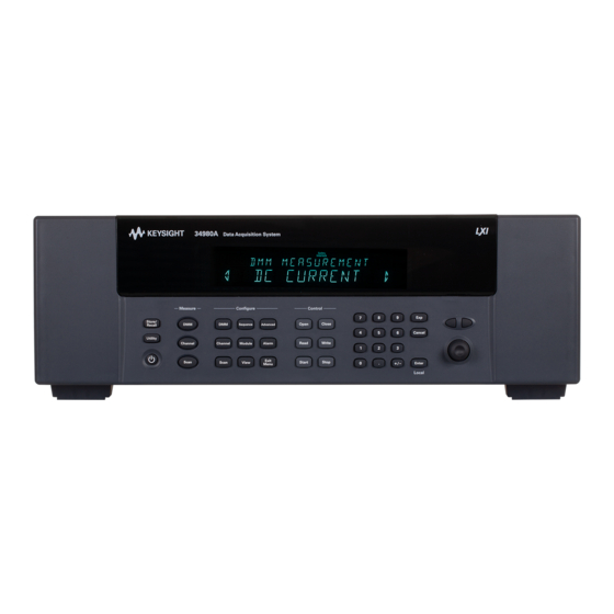
- Page 1 Keysight 34980A Multifunction Switch/ Measure Unit Mainframe User’s Guide Distributed by: Sie haben Fragen oder wünschen eine Beratung? Angebotsanfrage unter 07121 / 51 50 50 oder über info@datatec.de...
- Page 2 Software. The EULA and the license set CONTAINED HEREIN. SHOULD Edition forth therein, does not require or KEYSIGHT AND THE USER HAVE A permit, among other things, that SEPARATE WRITTEN AGREEMENT Edition 10, August 20, 2019 Keysight: (1) Furnish technical...
-
Page 3: Safety Symbols
Caution, risk of electric shock Caution, risk of danger (refer to this Frame or chassis (ground) terminal manual for specific Warning or Caution information) Standby supply. Unit is not completely disconnected from ac mains when switch is off Keysight 34980A Mainframe User’s Guide... -
Page 4: Additional Safety Notices
Failure to comply with these precautions or with specific warnings or instructions elsewhere in this manual violates safety standards of design, manufacture, and intended use of the instrument. Keysight Technologies assumes no liability of the customer’s failure to comply with the requirements. -
Page 5: Do Not Remove The Instrument Cover
Environmental Conditions Keysight 34980A is designed for indoor use in an installation category II and low condensation environment. Table below shows the general environmental conditions for this instrument. Refer to the product data sheet at https://literature.cdn.keysight.com/litweb/pdf/5989-1437EN.pdf... -
Page 6: Waste Electrical And Electronic Equipment (Weee) Directive 2002/96/Ec
To return this unwanted instrument, contact your nearest Keysight Service Center, or visit http://about.keysight.com/en/companyinfo/environment/takeback.shtml for more information. Sales and Technical Support To contact Keysight for sales and technical support, refer to the support links on the following Keysight websites: – www.keysight.com/find/34980a (product-specific information and support, software and documentation updates) –... -
Page 7: Table Of Contents
........31 Keysight 34980A Mainframe User’s Guide... - Page 8 ......83 Operating the 34980A using the Integrated Web Browser Interface . . 84 Launching the Web Interface .
- Page 9 ......132 2-Wire Versus 1-Wire Mode ......134 Keysight 34980A Mainframe User’s Guide...
- Page 10 ......179 Using Alarms With the Digital Modules ..... 181 Keysight 34980A Mainframe User’s Guide...
- Page 11 ........206 Introduction to the Plug-In Modules for the 34980A User’s Guides for the 34980A’s Plug-In Modules...
- Page 12 THIS PAGE HAS BEEN INTENTIONALLY LEFT BLANK. Keysight 34980A Mainframe User’s Guide...
- Page 13 Introduction to the 34980A Data Acquisition Overview Signal Routing and Switching Measurement Input Control Output This chapter provides an overview of a computer-based data acquisition and measurement control system using the Keysight 34980A Multifunction Switch/ Measure Unit and typical plug-in modules.
-
Page 14: Introduction To The 34980A
Introduction to the 34980A Data Acquisition Overview You can use the Keysight 34980A as a stand-alone instrument, but for most applications you will want to take advantage of its PC connectivity and remote operation capabilities. A simplified data acquisition system is shown below. -
Page 15: Measurement Software
Keysight 34832A BenchLink Data Logger Pro is a Windows®-based application available on CD from Keysight. It is designed to make it easy to use the 34980A with your PC (over GPIB, USB or LAN) for collecting and analyzing data. You program the desired measurement, scan and data logging requirements using an intuitive, tabbed spreadsheet environment;... - Page 16 The BenchLink Data Logger Pro software provides several advanced features not available in the standard BenchLink Data Logger software (which ships for free on CD-ROM with every 34980A ordered with an internal DMM). Particularly, the Pro version allows for customized action scripts, conditional control of external instruments, decision making or program initiation based on limit checks and alarm events, and advanced math operations.
-
Page 17: Data Acquisition Circuitry
These software tools can also be used with the 34980A: – Keysight IO Libraries Suite (shipped on CD with the 34980A) – Keysight IntuiLink – Keysight VEE (an evaluation copy of the VEE Pro software is shipped on CD with the 34980A) – National Instruments LabVIEW –... - Page 18 The 34980A provides four 2-wire internal Analog Buses for easier signal routing. You can route your measurements directly to the optional internal DMM using the 34980A multiplexer and matrix modules or you can connect to external signals via the Analog Bus connector located on the instrument's rear panel. Since four...
-
Page 19: Plug-In Modules
Introduction to the 34980A Plug-In Modules The 34980A offers a complete selection of plug-in modules to give you high-quality measurement, switching, and control capabilities. The plug-in modules communicate with the main system processor via the internal digital bus. The multiplexer modules also connect to the internal DMM via the internal Analog Buses. -
Page 20: Transducers And Sensors
Transducers and sensors convert a physical quantity into an electrical quantity. The electrical quantity is measured and the result is then converted to engineering units by the 34980A's main system processor. For example, when measuring a thermocouple, the instrument measures a dc voltage and mathematically converts it to a corresponding temperature in °C, °F, or K. -
Page 21: Alarm Limits
Introduction to the 34980A Alarm Limits The 34980A has four alarms which you can configure to alert you when a reading exceeds specified limits on a channel during a scan. You can assign a high limit, a low limit, or both to any configured channel in the scan list. You can assign multiple channels to any of the four available alarms (numbered 1 through 4). -
Page 22: Signal Routing And Switching
Introduction to the 34980A Signal Routing and Switching The switching capabilities of the plug-in modules available with the 34980A provide test system flexibility and expandability. You can use the switching plug-in modules to route signals to and from your test system or multiplex signals to the internal DMM or external instruments. - Page 23 Test 1 Test 2 In a matrix switch configuration, any one of the signal sources can be connected to any one of the test inputs. Be aware that with a matrix, it is possible to connect Keysight 34980A Mainframe User’s Guide...
-
Page 24: Rf And Microwave Switching
RF and Microwave Switching A variety of RF and microwave switch modules are also available for the 34980A. This includes RF multiplexers (34941A, 34942A), SPDT switching from dc to 20 GHz (34946A, 34947A), and a switch/attenuator driver module (34945A) that allows you to control switches or attenuators external to the 34980A mainframe. -
Page 25: Measurement Input
Introduction to the 34980A Measurement Input The 34980A allows you to combine a DMM (either internal or external) with multiplexer channels to create a scan. During a scan, the instrument connects the internal DMM to the configured multiplexer channels one at a time and makes a measurement on each channel. - Page 26 Analog-to-Digital Conversion (ADC) The ADC takes a prescaled dc voltage from the signal-conditioning circuitry and converts it to digital data for output and display on the 34980A front panel. The ADC governs some of the most basic measurement characteristics. These include measurement resolution, reading speed, and the ability to reject spurious noise.
-
Page 27: Scanning
You can configure the event or action that controls the onset of each sweep through the scan list (a sweep is one pass through the scan list): – You can set the instrument's internal timer to automatically scan at a specific interval as shown below. Keysight 34980A Mainframe User’s Guide... - Page 28 – You can start a scan when an external TTL trigger pulse is received. – You can start a scan when an alarm event is logged on the channel being monitored. For more information on scanning, see “Scanning” on page 148. Keysight 34980A Mainframe User’s Guide...
-
Page 29: Scanning With External Instruments
If your application doesn't require the built-in measurement capabilities of the 34980A, you can order the mainframe without the internal DMM. In this configuration, you can use the 34980A for signal routing or control applications. If you install a multiplexer plug-in module, you can use the system for scanning with an external instrument. - Page 30 34980A and an external instrument. The 34980A must notify the external instrument when a relay is closed and fully settled (including channel delay). The 34980A outputs a Channel Closed pulse. In response, the external instrument must notify the 34980A when it has finished its measurement and is ready to advance to the next channel in the scan list.
-
Page 31: The Digital Modules
8-bits. You can combine ports to read 16- or 32-bit words. Bit 0 Bit 7 Bit 8 Bit 15 Bit 16 Bit 23 Bit 24 Bit 31 Keysight 34980A Mainframe User’s Guide... - Page 32 - 1). The count rolls over to "0" after reaching the maximum allowed value. You can configure the totalizer to read without affecting the count or reset the count to zero without losing any counts. Keysight 34980A Mainframe User’s Guide...
-
Page 33: Control Output
Introduction to the 34980A Control Output In addition to signal routing and measurement, you can also use the 34980A to provide simple control outputs. For example, you can control external high-power relays using the GP switch modules or a digital output channel. - Page 34 500 V steps on any or all four channels. You can set the output current to any value between -20 mA and +20 mA, in 630 nA steps on any or all four channels. Keysight 34980A Mainframe User’s Guide...
-
Page 35: The Actuator / General-Purpose Switches
– The actuator switches can also be used to control power devices. When used with high-power devices, however, it is critical that you provide protection to the switch from capacitive and inductive loads to ensure maximum relay life. Keysight 34980A Mainframe User’s Guide... - Page 36 Introduction to the 34980A THIS PAGE HAS BEEN INTENTIONALLY LEFT BLANK. Keysight 34980A Mainframe User’s Guide...
- Page 37 Operating the 34980A using the Integrated Web Browser Interface 34980A Documentation Map This chapter provides an overview of the 34980A’s controls, displays and connections; module assembly, wiring and installation instructions; and some basics of operation with examples. It is designed to allow you to gain quick...
-
Page 38: Getting Started
Getting Started Front Panel at a Glance The On/Standby switch is used to toggle the 34980A between On and Standby modes only. To turn the unit off, remove the power cord. The Utility key accesses menus to configure Remote I/O (LAN, GPIB, and USB) operation, set Date and Time, and configure other system-related instrument parameters. - Page 39 Configure keys select functions and set function parameters. Measure keys execute and monitor measurements. Depending on which measurement key you use, you can have complete/direct control over the switching and measurement operation, or you can have the 34980A automatically control these to capture the desired data.
-
Page 40: Rear Panel At A Glance
Warning. Risk of electric shock Caution. Refer to accompanying descriptions in User’s Guide Alternating Current Mainframe Chassis Ground Access to Analog Buses (shown with removable cover installed). For pinouts, see page Module installed in slot 1 Slot identifier Keysight 34980A Mainframe User’s Guide... - Page 41 LAN connector (10Base T/100Base Tx) USB 2.0 connector External trigger input. For pinouts, see page Internal DMM option mark. If you ordered the internal DMM option, the circle is marked black. IEEE 488.2 GPIB Connector Chassis ground screw Keysight 34980A Mainframe User’s Guide...
-
Page 42: Rear Panel Connector Pinouts
Getting Started Rear Panel Connector Pinouts External Trigger/Alarms Connector (Male D-Sub) Keysight 34980A Mainframe User’s Guide... -
Page 43: Analog Bus Connector (Female D-Sub)
Getting Started Analog Bus Connector (Female D-Sub) Keysight 34980A Mainframe User’s Guide... -
Page 44: Annunciator Display Indicators
D-sub connector of a module. For more information, see page 131 and the User’s Guides for the appropriate Multiplexer Modules. Trig Lit when the 34980A is waiting for an external or manual trigger during scans. Keysight 34980A Mainframe User’s Guide... - Page 45 Lit when Offset Compensation has been specified for a given measurement. This appears on the display after you have selected the offset compensation function via the front panel or remote interface. For more information, see “Offset Compensation” on page 142 A measurement is in progress. Keysight 34980A Mainframe User’s Guide...
-
Page 46: Installing And Connecting Modules
Getting Started Installing and Connecting Modules For most applications, prior to using the 34980A you will select and install modules, and make connections with terminal blocks or cabling. The following sections illustrate module and terminal block installation. Removing a Slot Cover... -
Page 47: Installing A Module
1 Install the module into a mainframe slot until it fully seats with the backplane connector. 2 Using a Pozidriv #1 screwdriver, tighten the two screws to secure the module in the mainframe. Installation is now complete. Keysight 34980A Mainframe User’s Guide... - Page 48 Getting Started Installing a Module for Use with Terminal Blocks All of the 34980A plug-in modules, except the RF and microwave modules, can be used with a compatible terminal blocks (optional accessories 349xxT), which provide screw terminals or solder cup connections for your external wiring. If you...
- Page 49 3 Fit the terminal block support sleeve against the module so the openings on the sleeve line up with the connectors and the center screw hole as shown. 4 Replace the panhead screw. Then replace and tighten the two flathead screws to secure the sleeve to the module. Keysight 34980A Mainframe User’s Guide...
- Page 50 Before you begin this task, make sure you have disconnected power from all WARNING external field wiring you will be connecting to the terminal block. For plug-in module pinout diagrams and additional information, refer to the NOTE User's Guide(s) shipped with the module(s). Keysight 34980A Mainframe User’s Guide...
- Page 51 3 Make connections to the individual terminals as appropriate. Use a suitable wire type, gauge and insulation for your application (typical is 20 AWG; the terminals can accommodate a maximum of 18 AWG). Use a 2.5 mm cable tie as shown for additional strain relief. Keysight 34980A Mainframe User’s Guide...
- Page 52 4 To replace the terminal block cover, slide the cover tabs into the tab holders on the terminal block as shown. Press down on the cover until it snaps securely into place. Continue with the next section to install the terminal block to the module. Keysight 34980A Mainframe User’s Guide...
- Page 53 1 Push the levers on the terminal block to the fully-open position as shown below. Then slide the terminal block into the instrument-mounted support sleeve... Terminal Block Support Sleeve 34980A Mainframe …until the terminal block stops at the two points indicated by the arrows below. Keysight 34980A Mainframe User’s Guide...
- Page 54 Getting Started 2 Carefully rotate the levers upward as shown… …until both levers are locked in the closed position. Keysight 34980A Mainframe User’s Guide...
-
Page 55: Instrument Rack Mounting
2 rails and associated hardware for reverse mounting in an Keysight cabinet – For forward rack mounting, use the short brackets from the Keysight Standard rack mount kit or Y1130A Rack Mount Kit. For Keysight rack cabinets, use the E3663A Basic Rail Kit. - Page 56 Getting Started – For reverse rack mounting use the longer brackets (see figure below) from the Y1130A Rack Mount Kit. For Keysight rack cabinets, use the E3664AC Third Party Rail Kit. Keysight 34980A (shown with Reverse Rack Mount brackets installed)
- Page 57 Getting Started 425.6 mm (16.76 in) 367.7 mm (14.48 in) 101.9 mm (4.01 in) 70.4 mm (2.78 in) Keysight 34980A Dimensions (shown with Reverse Rack Mount brackets installed) Keysight 34980A Mainframe User’s Guide...
-
Page 58: Operating The 34980A From The Front Panel Keyboard
Before you can operate the front panel keyboard, connect the power cord to the NOTE 34980A and turn on the power. If the instrument does not power on properly, contact Keysight Technologies Technical Support. At power on, all segments on the front panel are displayed and all lighted keys temporarily turn on. - Page 59 – Set measurement function parameters The Scan Menu – Set trigger-in parameters – Set sweep count – Set sample count The Sequence Menu – View a sequence command string – Execute the sequence – Delete sequence definitions Keysight 34980A Mainframe User’s Guide...
- Page 60 – Configure a high limit, a low limit, or both for the displayed channel – Select the slope (rising or falling edge) for the four alarm output lines The Exit Menu Key Press to leave the current menu, saving all changes made in that menu Keysight 34980A Mainframe User’s Guide...
-
Page 61: Menu Example 1: Setting The Time And Date
Getting Started Menu Example 1: Setting the Time and Date In this example, you will learn the fundamentals of using the 34980A front-panel menus by setting the date and time. Begin by pressing the Utility menu key, then use the Utility key, knob and arrow keys to navigate the menu as shown below. - Page 62 – To move the display cursor position, use the left and right arrow keys. – When you have entered all required parameters, the lighting on the menu key will turn off. Keysight 34980A Mainframe User’s Guide...
-
Page 63: Menu Example 2: Opening And Closing Channel Relays
4 With channel 1027 selected (shown in green channel field on display), toggle the Close and Open keys to close and open the selected channel. Note that the display shows OPEN or CLOSED, indicating the status of the channel. Keysight 34980A Mainframe User’s Guide... - Page 64 Getting Started Keysight 34980A Mainframe User’s Guide...
-
Page 65: Using The Measure Keys
Depending on which measurement key you select, you can have complete/direct control over the switching and measurement operations, or you can allow the 34980A to automatically control the measurement to capture the desired data. -
Page 66: Menu Example 3: Configuring The Dmm For A Measurement
This example uses the internal DMM for a measurement. It can be used with any of the multiplexer modules (34921A, 34922A, 34923A, 34924A, or 34925A). If you have disabled your internal DMM, don't have one installed in your 34980A, or are not using a multiplexer module, skip this example. - Page 67 All unmodified parameters within the menu remain unchanged. 7 Within the Measure key group, press DMM. Note that the key lights and continuous ac voltage measurements are made using the internal DMM. Keysight 34980A Mainframe User’s Guide...
- Page 68 The internal DMM acted as a stand-alone instrument and measured whatever ac voltages happened to be present on the Analog Buses. Pressing DMM (in the Measure key group) also allowed you to continuously monitor measurements on the front panel. Keysight 34980A Mainframe User’s Guide...
-
Page 69: Menu Example 4: Configuring A Channel For A Measurement
This example uses the internal DMM for a measurement. It can be used with any of the multiplexer modules (34921A, 34922A, 34923A, 34924A, or 34925A). If you have disabled your internal DMM, don't have one installed in your 34980A, or are not using a multiplexer module, skip this example. - Page 70 8 At the CHANNEL LABEL choice, use the knob (to select alphanumeric characters) and the arrow keys (to select the cursor position) to enter a custom channel label. 9 Press the lighted Channel key to save the assigned channel label and all other changes you made. Keysight 34980A Mainframe User’s Guide...
- Page 71 Channel 1014 (for this example, don't change any other measurement parameters): – Channel: 1014 – Measurement Function: AC Volts – Range: 1V 13 Press EXIT MENU to accept the new settings and retain all other parameters in this menu. Keysight 34980A Mainframe User’s Guide...
- Page 72 – You configured channel 14 for ac voltage measurements, then started, viewed results, and stopped continuous ac voltage measurements on channel 14. – You scrolled between channels 14 and 16 to alternatively start, monitor, and stop continuous measurements on the channels. Keysight 34980A Mainframe User’s Guide...
-
Page 73: Connecting The 34980A To Your Computer
Getting Started Connecting the 34980A to Your Computer To easily configure and verify an interface connection between the 34980A and NOTE your PC, you can use the Keysight IO Libraries Suite or an equivalent. – The Keysight IO Libraries Suite—along with installation instructions—is provided on the Automation-Ready CD, which is shipped with your 34980A. -
Page 74: Connecting Over Lan
Getting Started Connecting Over LAN Selecting the LAN network type You can connect and configure your 34980A for Site LAN or Isolated (non-site) LAN operation. – A Site LAN network is defined as a local area network (LAN) in which... - Page 75 Instrument Instrument The diagrams above show examples of typical site LAN and isolated LAN networks. Select the LAN network type that you will use to connect the 34980A to your computer. Then follow the corresponding procedures shown on “Connecting Via Site LAN”...
- Page 76 4 Press EXIT MENU, which saves any changes and defaults all other parameters in the Utility menu. 5 Wait for the DHCP server to assign a valid address; this operation can take between 30 seconds and one minute to complete). Keysight 34980A Mainframe User’s Guide...
- Page 77 IP address in the space below: 34980A IP Address: ___________________________ 7 Press EXIT MENU. 8 Now you can use the integrated 34980A Web Browser Interface to access and control the instrument. See “Launching the Web Interface” on page 85 for more information.
- Page 78 LAN Connection CAT5 Crossover Cable 34980A 1 Using the CAT5 crossover cable provided with the 34980A, connect your computer to the 34980A. 2 Make sure power is applied to your computer and verify that the operating system is fully booted. Then apply power to the 34980A.
- Page 79 Getting Started 3 Using the flow diagram below, navigate through the 34980A front-panel Utility menu. At the IO PORT menu, select LAN. At the LAN SETTINGS menu, select MODIFY and set DHCP to OFF (note that ON is the factory default state).
-
Page 80: Connecting Over Gpib
LAN settings. Write down the IP address in the space below: 34980A IP Address: ___________________________ 6 Press EXIT MENU. 7 Now you can use the integrated 34980A Web Browser Interface to access and control the instrument. See “Launching the Web Interface”... -
Page 81: Connecting Over Usb
NO YES (Use knob to select YES) 6 Press Utility again to display the GPIB Address. The 34980A is shipped from the factory with a default GPIB ADDRESS of 9. To change the address, use the know or arrow keys. - Page 82 8 Cycle power to the unit. When it reboots, the USB connection will be enabled. 9 Use the Connection Expert utility of the Keysight IO Libraries Suite to add the 34980A and verify a connection. If you have installed any other I/O software, refer to documentation included with that software.
-
Page 83: Communicating With The 34980A
34980A. However, Keysight has designed drivers that work best in recommended environments, as shown in the table below. To install drivers and their associated Help files, refer to the 34980A Product Reference CD shipped with your 34980A. This CD also contains a collection of example programs for your reference. -
Page 84: Operating The 34980A Using The Integrated Web Browser Interface
Getting Started Operating the 34980A using the Integrated Web Browser Interface You can use the 34980A's Web Browser Interface for remote LAN access and control (configuration, troubleshooting and monitoring) of the instrument via a Java-enabled Web browser, such as Microsoft® Internet Explorer. -
Page 85: Launching The Web Interface
3 From the LAN Settings dialog, select/activate the bypass proxy server for local addresses (exact terminology depends on your browser). 4 Exit the Internet Options window. 5 Enter the IP address of the 34980A in the Address field and press return. Either refer to the IP address you wrote on page 77... - Page 86 Getting Started 6 After entering the appropriate IP address, the 34980A Web Interface's Welcome Window should appear. The procedures in the following subsections will help you understand tasks NOTE commonly performed using the 34980A's Web Interface. For additional help on using the interface, click the ?Help with the Page tab on the lower-left corner of the Web Interface window.
-
Page 87: Displaying The Browser Web Control Page
Getting Started Displaying the Browser Web Control Page 1 From the Welcome Window, click the Browser Web Control tab on the left side of the window to display the Browser Web Control page. Keysight 34980A Mainframe User’s Guide... -
Page 88: Selecting The "Allow Full Control" Mode
Getting Started 2 From this page, you can view and modify the configuration of the modules currently installed in the 34980A. When you first launch this page, the configuration of the module in the lowest numbered slot is shown (shown in bold text). To view the configuration of a different module, click on the desired module name from the list (slots are numbered 1 through 8). -
Page 89: Setting A Web Browser Password
Getting Started Setting a Web Browser Password If desired, you can control access to the 34980A Web Interface using password protection. As shipped from the factory, no password is set. To set a password (available from the front panel only), navigate to the WEB PASSWORD menu selection from the 34980A front panel, as follows: Utility >... -
Page 90: Closing And Opening Channel Relays
2 You can also open and close the four Analog Bus relays by left-clicking the graphics of these relays. The Analog Bus Overview display located near the top of the window shows the slot-by-slot status of the four Analog Buses. Keysight 34980A Mainframe User’s Guide... -
Page 91: Modifying The Channel Configuration
The Channel Configuration dialog box for that channel is displayed. 2 As an example, change the label on Channel 1001 to DUT_1. Click OK. Keysight 34980A Mainframe User’s Guide... -
Page 92: Sending Scpi Commands Via The Web Interface
You must be in the Allow Full Control mode to send instrument commands to the NOTE 34980A. The Web Interface provides a utility to send SCPI commands to the 34980A via the SCPI Command Interface window. The procedure below shows how to access this window and send commands. - Page 93 Select commonly used commands to send to the instrument. c Enter SCPI commands to send to the instrument. You may: – Use Write to send the command to the instrument. – Use Read to read the response back from the instrument. Keysight 34980A Mainframe User’s Guide...
- Page 94 3 In the Command History field, you can view the last 20 commands sent to the instrument. 4 You can use the SCPI Quick Reference button to access a syntax summary of all SCPI commands for the 34980A. For basic SCPI command syntax and examples, see “SCPI Language Conventions”...
-
Page 95: 34980A Documentation Map
These chapters are part of this Mainframe menu content and operation User’s Guide, shipped as a printed manual with the 34980A and a PDF file on the 34980A “Operating the 34980A from the Product Reference CD. You can also download Front Panel Keyboard”... - Page 96 Add itional Comments Calibrate or troubleshoot the 34980A 34980A Service Guide Shipped as a printed manual with the 34980A and a PDF file on the 34980A Product Reference CD. You can also download the manual from the Keysight Web site at: www.keysight.com/find/34980A.
- Page 97 Alarm Limits Sequences System-Related Operations Calibration Overview Factory Reset State Instrument Preset State This chapter provides detailed information about the features of the Keysight 34980A, whether you will be operating the instrument from the front panel or over the remote interface.
- Page 98 Features and Functions For general information about the plug-in modules, see Chapter 4, “Introduction to the Plug-In Modules for the 34980A” . For information specific to a particular plug-in module, see the separate User’s Guide provided for that module. Keysight 34980A Mainframe User’s Guide...
-
Page 99: Front Panel Features
Front Panel Features Front Panel Display The 34980A features a dual-line, alphanumeric display, plus a set of text and symbolic annunciators to indicate operational modes and error conditions. At power on, all segments on the front panel are displayed and all lighted keys temporarily turn on. - Page 100 44. Self-Guiding Menus The 34980A utilizes context-sensitive, self-guiding menus for you to configure measurement functions. In general, the front panel knob and arrow keys are the primary tools in menu navigation. A list of menu navigation hints is provided below: –...
-
Page 101: Front Panel Controls
Features and Functions Front Panel Controls The front panel keys control local operation of the 34980A. They are illustrated and described in detail in “Front Panel at a Glance” on page 38. Familiarize yourself with the operation of these keys by following the Menu Examples in the Getting Started chapter, beginning with “Menu Example 1: Setting the Time and... -
Page 102: Basic Operating Modes
34980A. However, for most test applications, the 34980A will be located remotely from the devices under test, and you will send commands to it using its remote interface connectivity modes (e.g. -
Page 103: Scpi Commands
SCPI (Standard Commands for Programmable Instruments). For complete details on the SCPI commands, see the Programmer’s Reference NOTE Help file included on the Keysight 34980A Product Reference CD. SCPI Language Conventions Throughout this guide, the following conventions are used for SCPI command syntax for remote interface programming: –... -
Page 104: Rules For Using A Channel List
Features and Functions Rules for Using a Channel List Many of the SCPI commands for the 34980A include a channel list parameter which allows you to specify one or more channels. From the remote interface, the channel number has the form (@sccc), where s is the mainframe slot number (1 through 8) and ccc is the channel number. -
Page 105: Remote Interface Configuration
Features and Functions Remote Interface Configuration To easily configure and verify an interface connection between the 34980A and NOTE your PC, you can use the Keysight IO Libraries Suite or an equivalent. – The Keysight IO Libraries Suite—along with installation instructions—is provided on the Automation-Ready CD, which is shipped with your 34980A. -
Page 106: Gpib Interface
Features and Functions The 34980A Web Browser Interface is covered fully in Chapter 2. For an overview of the Web Browser Interface (LAN only), see “Operating the 34980A using the Integrated Web Browser Interface” on page 84. GPIB Interface Each device on the GPIB (IEEE-488) interface must have a unique address. You can set the instrument’s address to any value between 0 and 30. - Page 107 LAN interface. If you change the DHCP setting, you must cycle power on the 34980A to activate the new setting. – When DHCP is enabled (factory setting), the instrument will try to obtain an IP address from a DHCP server.
- Page 108 However, if the DHCP server fails to assign a valid IP address, the currently configured static IP address will be used. If you change the IP address, you must cycle power on the 34980A to activate the new setting.
- Page 109 The Auto-IP standard automatically assigns an IP address to the 34980A when on a network that does not have DHCP servers. If you change the Auto-IP configuration, you must cycle power on the 34980A to activate the new setting. – Auto-IP allocates IP addresses from the link-local address range (169.254.xxx.xxx).
- Page 110 Default Gateway. Contact your network administrator to determine if subnetting is being used and for the correct Subnet Mask. If you change the Subnet Mask, you must cycle power on the 34980A to activate the setting.
- Page 111 Subnet Mask setting. Contact your network administrator to determine if a gateway is being used and for the correct address. If you change the Default Gateway, you must cycle power on the 34980A to activate the new setting. – The default for the 34980A is “0.0.0.0” (no gateway, and subnetting is not being used).
- Page 112 The Host Name is the host portion of the domain name, which is translated into an IP address. If you change the Host Name, you must cycle power on the 34980A to activate the new setting. – The default Host Name for the 34980A is “A-34980A-nnnnn”, where nnnnn represents the last five digits of the instrument’s serial number.
- Page 113 IP addresses. Contact your network administrator to determine if DNS is being used and for the correct address. If you change the DNS address, you must cycle power on the 34980A to activate the new setting. – The default DNS Address for the 34980A is “0.0.0.0”.
- Page 114 A domain name is a registered name on the Internet, which is translated into an IP address. This feature is available from the remote interface only. If you change the Domain Name, you must cycle power on the 34980A to activate the new setting.
-
Page 115: Clearing 34980A Memory
Features and Functions Clearing 34980A Memory For security reasons, you may want to clear memory in the 34980A. Volatile Memory The following settings are stored in volatile memory: – All measurement results – Any non-default internal DMM settings – Any non-default channel configurations –... - Page 116 Features and Functions Remote Interface Operation: To clear the stored instrument states, use the MEMory:STATe:DELete:ALL command. To clear non-volatile memory, with the exception of the LAN MAC address and USB ID, use the SYSTem:SECurity:IMMediate command. Keysight 34980A Mainframe User’s Guide...
-
Page 117: Analog Bus And Internal Dmm Considerations
40°C. Do not use in locations where conductive dust or electrolytic salt dust may be present. The 34980A should be operated in an indoor environment where temperature and humidity are controlled. Condensation can pose a potential shock hazard. Condensation can occur when the instrument is moved from a cold to a warm environment, or if the temperature and/or humidity of the environment changes quickly. -
Page 118: Electrical Operating Conditions
Features and Functions Electrical Operating Conditions To avoid electric shock, turn off the 34980A and disconnect or de-energize WARNING all field wiring to the modules and the Analog Bus connector before removing any module or slot cover. Transients The Analog Buses and the optional internal DMM are designed to safely withstand occasional transient overvoltages up to 1000 Vpeak. -
Page 119: General Measurement Configuration
Overview of Measurement Modes Two modes of operation are available with the 34980A, depending on the level of switching and measurement that you wish to directly control: the Stand-Alone DMM Mode and the Scanning Mode. - Page 120 In the Scanning Mode, the 34980A automatically controls a sequence of measurements using the internal DMM, possibly across multiple channels, and stores the results in memory. The 34980A closes and opens the appropriate channel relays and Analog Bus relays required for the sequence. The following...
- Page 121 READ? command performs a scan of the channels in the scan list. – If you specify a <ch_list>, regardless of whether a scan list is currently defined, the READ? command performs a “temporary” scan of the specified channels (independent of the present scan list). Keysight 34980A Mainframe User’s Guide...
-
Page 122: Analog Buses
Analog Buses The 34980A provides four 2-wire internal Analog Buses for easier signal routing. You can route your measurements directly to the internal DMM using the 34980A multiplexer and matrix modules, or you can connect to external signals via the Analog Bus connector located on the instrument’s rear panel (see connector... -
Page 123: Measurement Functions
[e] 1 k or higher range used unless 100 series resistors are bypassed on module. Ω Ω 10 k or higher range used for loads over approximately 300 due to series resistance of FET channels. Keysight 34980A Mainframe User’s Guide... -
Page 124: Measurement Range
3 Hz and 300 kHz. The range parameter is required only to specify the resolution. Therefore, it is not necessary to send a new command for each new frequency to be measured. Keysight 34980A Mainframe User’s Guide... -
Page 125: Measurement Resolution
– Changing the number of digits does more than just change the resolution of the instrument. It also changes integration time, which is the measurement sampling period for the instrument’s A/D converter. See “Custom A/D Integration Time” on page 127 for more information. Keysight 34980A Mainframe User’s Guide... - Page 126 2041 (current measurements are allowed only on channels 41 through 44 on the 34921A). MEAS:CURR:AC? 1,1E-6,(@2041) You can also select the resolution using the SENSe commands. For example, the following command specifies a 2-wire ohms measurement with 100Ω of resolution on channel 1003. SENS:RES:RES 100,(@1003) Keysight 34980A Mainframe User’s Guide...
-
Page 127: Custom A/D Integration Time
– The instrument selects 1 PLC when the measurement function is changed and after a Factory Reset (*RST command). An Instrument Preset (SYSTem:PRESet command) or Card Reset (SYSTem:CPON command) does not change the integration time setting. Keysight 34980A Mainframe User’s Guide... -
Page 128: Autozero
DMM or Channel (Configure) > AUTO ZERO Remote Interface Operation: The OFF and ONCE parameters have a similar effect. Autozero OFF does not issue a new zero measurement. Autozero ONCE issues an immediate zero measurement. [SENSe:]<function>:ZERO:AUTO {OFF|ONCE|ON} [,(@<ch_list>)] Keysight 34980A Mainframe User’s Guide... -
Page 129: Trigger Delay
– The CONFigure and MEASure? commands set the trigger delay to Automatic. – The instrument selects an automatic trigger delay after a Factory Reset (*RST command). An Instrument Preset (SYSTem:PRESet command) or Card Reset (SYSTem:CPON command) does not change the setting. Keysight 34980A Mainframe User’s Guide... -
Page 130: Automatic Trigger Delays
1.0 second Fast (200 Hz) 120 ms Frequency, Period: AC Fil ter Trigger Delay Slow (3 Hz) 600 ms Medium (20 Hz) 300 ms Fast (200 Hz) 100 ms Digital Input, Totalize: Trigger Delay 0 seconds Keysight 34980A Mainframe User’s Guide... -
Page 131: Safety Interlock
– The simulation setting is stored in volatile memory and will be lost when power is turned off. To re-enable the simulation mode after power has been off, you must send the command again. Remote Interface Operation: SYSTem:ABUS:INTerlock:SIMulate {OFF|ON} Keysight 34980A Mainframe User’s Guide... -
Page 132: User-Defined Channel Labels
Front Panel Operation: Channel (Configure) > CHANNEL LABEL To define the channel label, press the arrow keys to move the cursor to a specific position and then turn the knob to select the desired letter or number. Keysight 34980A Mainframe User’s Guide... - Page 133 1. The factory-default labels are assigned to all channels on the module in slot 1. ROUT:CHAN:LABEL:CLEAR:MOD 1 The following command clears all user-defined labels on all modules installed in the 34980A. The factory-default labels are assigned to all channels on all installed modules. ROUT:CHAN:LABEL:CLEAR:MOD ALL Keysight 34980A Mainframe User’s Guide...
-
Page 134: 2-Wire Versus 1-Wire Mode
User’s Guides shipped with the modules. If you change the module configuration, you must cycle power on the 34980A to activate the new setting. – To determine whether the module is in the 2-wire or 1-wire configuration, check the module description shown on the front panel when the module is selected, or send the SYSTem:CTYPe? or SYSTem:CDEScription? command. -
Page 135: Temperature Measurement Configuration
Factory Reset (*RST command). An Instrument Preset (SYSTem:PRESet command) or Card Reset (SYSTem:CPON command) does not change the units setting. Front Panel Operation: DMM or Channel (Configure) > TEMPERATURE > UNITS Remote Interface Operation: UNIT:TEMP {C|F|K}[,(@<ch_list>)] Keysight 34980A Mainframe User’s Guide... -
Page 136: Thermocouple Measurements
If an open connection is detected (greater than 5 kΩ on the 10 kΩ range), the instrument reports an overload condition for that channel (or displays “OPEN T/C” on the front panel). Keysight 34980A Mainframe User’s Guide... - Page 137 The following commands use the SENSe command to set a fixed reference junction temperature of 40 degrees (always in °C) on channel 2003. SENS:TEMP:TRAN:TC:RJUN:TYPE,(@2003) SENS:TEMP:TRAN:TC:RJUN 40,(@2003) The following command enables the thermocouple check feature on the specified channel (opens are reported as “+9.90000000E+37”). SENS:TEMP:TRAN:TC:CHECK ON,(@2003) Keysight 34980A Mainframe User’s Guide...
-
Page 138: Rtd Measurements
You can also use the SENSe command to select the probe type, RTD type, and nominal resistance. For example, the following command configures channel 1003 for 4-wire measurements of an RTD with α = 0.00391 (channel 1003 is automatically paired with channel 1023 for the 4-wire measurement). Keysight 34980A Mainframe User’s Guide... -
Page 139: Thermistor Measurements
3001 for measurements of a 5 kΩ thermistor: CONF:TEMP THER,5000,(@3001) You can also use the SENSe command to select the probe type and thermistor type. For example, the following command configures channel 1003 for measurements of a 10 kΩ thermistor: SENS:TEMP:TRAN:THERM:TYPE 10000,(@1003) Keysight 34980A Mainframe User’s Guide... -
Page 140: Voltage Measurement Configuration
DMM. With AUTO OFF (default), the input resistance is fixed at 10 MΩ for all ranges. With AUTO ON, the input resistance is set to >10 GΩ for the three lowest dc voltage ranges. [SENSe:]<function>:IMPedance:AUTO {OFF|ON} [,(@<ch_list>)] Keysight 34980A Mainframe User’s Guide... -
Page 141: Ac Low Frequency Filter
The instrument selects the appropriate filter based on the frequency you specify (see table above). [SENSe:]VOLTage:AC:BANDwidth {3|20|200} [,(@<ch_list>)] If you omit the optional <ch_list> parameter, the command applies to the internal DMM. Keysight 34980A Mainframe User’s Guide... -
Page 142: Resistance Measurement Configuration
If you omit the optional <ch_list> parameter, the command applies to the internal DMM. For 4-wire measurements, specify the paired channel in Bank 1 (source) as the <ch_list> channel (channels in Bank 2 are not allowed in the <ch_list>). Keysight 34980A Mainframe User’s Guide... -
Page 143: Current Measurement Configuration
– The instrument selects the default 20 Hz (medium) filter after a Factory Reset (*RST command). An Instrument Preset (SYSTem:PRESet command) or Card Reset (SYSTem:CPON command) does not change the setting. Front Panel Operation: DMM or Channel (Configure) > AC FILTER Keysight 34980A Mainframe User’s Guide... - Page 144 The instrument selects the appropriate filter based on the frequency you specify (see table above). [SENSe:]CURRent:AC:BANDwidth {3|20|200} [,(@<ch_list>)] If you omit the optional <ch_list> parameter, the command applies to the internal DMM. Keysight 34980A Mainframe User’s Guide...
-
Page 145: Frequency Measurement Configuration
The instrument selects the appropriate timeout based on the frequency you specify (see table above). [SENSe:]FREQuency:RANGe:LOWer {3|20|200} [,(@<ch_list>)] If you omit the optional <ch_list> parameter, the command applies to the internal DMM. Keysight 34980A Mainframe User’s Guide... -
Page 146: Mx+B Scaling
– A Factory Reset (*RST command) turns off scaling, clears the scaling values on all channels, and sets the custom label to a null string (“ ”). An Instrument Preset (SYSTem:PRESet command) does not clear the scaling values and does not turn off scaling. Keysight 34980A Mainframe User’s Guide... - Page 147 Use the following commands to set the gain, offset, and custom measurement label. CALC:SCALE:GAIN 1.2,(@1003) CALC:SCALE:OFFSET 10,(@1003) CALC:SCALE:UNIT 'PSI',(@1003) After setting the gain and offset values, send the following command to enable the scaling function on the specified channel. CALC:SCALE:STATE ON,(@1003) Keysight 34980A Mainframe User’s Guide...
-
Page 148: Scanning
(oldest) readings stored. The most recent readings are always preserved. You can read the contents of memory at any time, even during a scan. Reading memory is not cleared when you read it. Keysight 34980A Mainframe User’s Guide... - Page 149 – When you add a digital read (digital modules) to a scan list, the corresponding channel is dedicated to the scan. The instrument issues a Card Reset to make that channel an input channel (the other channel is not affected). Keysight 34980A Mainframe User’s Guide...
-
Page 150: Adding Channels To The Scan List
However, the 34980A allows only one scan list at a time; you cannot scan some channels using the internal DMM and others using an external instrument. Readings are stored in 34980A memory only when the internal DMM is used. - Page 151 – To initiate a scan, use the INITiate or READ? command. Measurements are stored in memory. Each time you initiate a new scan, the instrument will clear the previous set of readings from memory. – To stop a scan in progress, use the ABORt command. Keysight 34980A Mainframe User’s Guide...
-
Page 152: Scan Trigger Source
Sweep 2 Sweep . . . Trigger Timer (0 to 359,999 seconds) Trigger-to-trigger interval – You can set the scan interval to any value between 0 seconds and 99:59:59 hours (359,999 seconds), with 1 ms resolution. Keysight 34980A Mainframe User’s Guide... - Page 153 – All readings from the scan are stored in volatile memory. Readings accumulate in memory until the scan is terminated (until the trigger count is reached or until you abort the scan). Keysight 34980A Mainframe User’s Guide...
- Page 154 For complete details on configuring and using alarms, refer to NOTE “Alarm Limits” on page 174. Keysight 34980A Mainframe User’s Guide...
- Page 155 Scan (Configure) > ALARM > ALARM TRIG MODE > SINGLE|CONTIN Remote Interface Operation: The following program segment configures the instrument to continuously scan when an alarm is detected. Keysight 34980A Mainframe User’s Guide...
- Page 156 Ext Trig Input connector (as viewed from rear of instrument) – You can specify a scan count which sets the number of external pulses the instrument will accept before terminating the scan. See “Trigger Count” page 157 for more information. Keysight 34980A Mainframe User’s Guide...
-
Page 157: Trigger Count
(oldest) readings stored; the most recent readings are always preserved. – You can specify a trigger count in conjunction with a sample count and a sweep count. The three parameters operate independent of one another, and Keysight 34980A Mainframe User’s Guide... -
Page 158: Sweep Count
(1 to 500,000 sweeps) Sweep count – The sweep count is valid only while scanning. If no channels have been assigned to the scan list, the specified sweep count is ignored (no error is generated). Keysight 34980A Mainframe User’s Guide... -
Page 159: Sample Count
The sample count applies to both scanning and stand-alone DMM measurements (with no scan list). The front-panel sample annunciator (“ * ”) turns on during each measurement. Sample Count (1 to 500,000 samples) Trigger Trigger Sample count for Stand-Alone DMM Mode Keysight 34980A Mainframe User’s Guide... - Page 160 – You can store at least 500,000 readings in memory and all readings are automatically time stamped. If memory overflows, the new readings will overwrite the first (oldest) readings stored; the most recent readings are always preserved. Keysight 34980A Mainframe User’s Guide...
-
Page 161: Channel Delay
The programmed channel delay overrides the default channel delay that the instrument automatically adds to each channel. Keysight 34980A Mainframe User’s Guide... - Page 162 – The CONFigure and MEASure? commands set the channel delay to automatic. A Factory Reset (*RST command) also sets the channel delay to automatic. Keysight 34980A Mainframe User’s Guide...
-
Page 163: Automatic Channel Delays
1 kΩ 2.0 ms 1.0 ms 10 kΩ 2.0 ms 1.0 ms 100 kΩ 25 ms 20 ms 1 MΩ 30 ms 25 ms 10 MΩ 200 ms 200 ms 100 MΩ 200 ms 200 ms Keysight 34980A Mainframe User’s Guide... -
Page 164: Reading Format
From the remote interface, you can specify which information you want returned with the readings. The examples below show a reading in relative and absolute format with all fields enabled. Keysight 34980A Mainframe User’s Guide... - Page 165 – The format settings are stored in volatile memory and will be lost when power is turned off or after a Factory Reset (*RST command). Remote Interface Operation: Use the following commands to select the reading format. FORMat:READing:ALARm ON FORMat:READing:CHANnel ON FORMat:READing:TIME ON FORMat:READing:TIME:TYPE {ABSolute|RELative} FORMat:READing:UNIT ON Keysight 34980A Mainframe User’s Guide...
-
Page 166: Non-Sequential Scanning
(*RCL command). – The scan order setting is stored in volatile memory and the ordered mode will be enabled when power is turned off or after a Factory Reset (*RST command). Remote Interface Operation: ROUTe:SCAN:ORDered {OFF|ON} Keysight 34980A Mainframe User’s Guide... -
Page 167: Viewing Readings Stored In Memory
– The INITiate command stores readings in memory. Use the FETCh? command to retrieve stored readings from memory (the readings are not erased when you read them). Keysight 34980A Mainframe User’s Guide... - Page 168 This allows you to continue a scan without losing data stored in memory (if memory becomes full, new readings will overwrite the first readings stored). The specified number of readings are cleared from memory, starting with the oldest reading. DATA:REMOVE? 12 Keysight 34980A Mainframe User’s Guide...
-
Page 169: Monitor Mode
(the Monitor ignores the totalizer reset mode). – If a channel that is currently being monitored is manually closed or opened, the Monitor operation will be disabled on that channel. Keysight 34980A Mainframe User’s Guide... - Page 170 To read the monitor data from the selected channel or the internal DMM, send the following command. Each reading is returned with measurement units, time stamp, channel number, and alarm status information (see “Reading Format” page 164). ROUTe:MONitor:DATA? Keysight 34980A Mainframe User’s Guide...
-
Page 171: Scanning With External Instruments
5 on the rear-panel Ext Trig connector. In response, the external instrument must notify the 34980A when it has finished its measurement and is ready to advance to the next channel in the scan list. The 34980A accepts a Channel Advance pulse on the Chan Adv input line (pin 6). - Page 172 “Scan Trigger Source” on page 152. – You can configure the event or action that notifies the 34980A to advance to the next channel in the scan list. Note that the Channel Advance source shares the same sources as the scan trigger. However, an error is generated if you attempt to set the channel advance source to the same source (other than IMMediate) used for the scan trigger.
- Page 173 Set trigger source TRIG:SOUR IMM Set trigger count TRIG:COUN 5 Set channel advance source ROUT:CHAN:ADV:SOUR EXT Initiate the scan INIT To configure the instrument for 4-wire external scanning, send the following command. ROUTe:CHANnel:FWIRe {OFF|ON}, (@<ch_list>) Keysight 34980A Mainframe User’s Guide...
-
Page 174: Alarm Limits
– You can assign an alarm to any configured channel and multiple channels can be assigned to the same alarm number. However, you cannot assign alarms on a specific channel to more than one alarm number. Keysight 34980A Mainframe User’s Guide... - Page 175 – As shown below, alarms are logged in the alarm queue only when a reading crosses a limit, not while it remains outside the limit and not when it returns to within limits. Keysight 34980A Mainframe User’s Guide...
- Page 176 You can configure the instrument to use the status system to generate a Service Request (SRQ) when alarms are generated. Refer to the Keysight 34980A Programmer’s Reference Help file for more information on the Status System. An alarm is enabled on the displayed channel.
- Page 177 To set the upper and lower alarm limits on the specified channels, use the following commands. CALC:LIMIT:UPPER 5.25,(@2001,2012) CALC:LIMIT:LOWER 0.025,(@2001,2012) To enable the upper and lower alarm limits on the specified channels, use the following commands. CALC:LIMIT:UPPER:STATE ON,(@2001,2012) CALC:LIMIT:LOWER:STATE ON,(@2001,2012) Keysight 34980A Mainframe User’s Guide...
-
Page 178: Viewing Stored Alarm Data
(one alarm event is read and cleared each time this command is executed). SYSTEM:ALARM? The following is an example of an alarm stored in the alarm queue (if no alarm data is in the queue, the command returns “0” for each field). Keysight 34980A Mainframe User’s Guide... -
Page 179: Using The Alarm Output Lines
Each alarm output line represents the logical “OR” of all channels assigned to that alarm number (an alarm on any of the associated channels will pulse the line). Alarms connector (as viewed from rear of instrument) Keysight 34980A Mainframe User’s Guide... - Page 180 – To select the output configuration for all four output lines, select: Alarm > ALARM OUT SIGNAL > TRACK|LATCH – To configure the slope of all four output lines, select: Alarm > ALARM OUT SLOPE > NEGATIVE|POSITIVE Keysight 34980A Mainframe User’s Guide...
-
Page 181: Using Alarms With The Digital Modules
– Pattern comparisons always start on the lowest-numbered channel in the bank and extend to all channels involved in the channel width. – Alarms are evaluated continuously on the digital modules, but alarm data is stored in reading memory only during a scan. Keysight 34980A Mainframe User’s Guide... - Page 182 CALC:COMP:DATA after being masked by CALC:COMP:MASK. Use CALC:COMP:MASK to designate the “don’t care” bits. Bits that you set to “0” in the mask are ignored. To enable the specified alarm mode, send the following command. Keysight 34980A Mainframe User’s Guide...
- Page 183 To configure an alarm on a totalizer channel, specify the desired count as the upper limit using the following command. CALCulate:LIMit:UPPer <count>,(@<ch_list>) To enable the upper limit on the specified totalizer channel, use the following command. CALCulate:LIMit:UPPer:STATe ON,(@<ch_list>) Keysight 34980A Mainframe User’s Guide...
-
Page 184: Sequences
The following tables summarizes the commands used to define, execute, and manage sequences. For more information, see the Keysight 34980A Programmer’s Reference Help file. Sequence Definition ROUTe:SEQuence:DEFine <name>, "<commands>"... -
Page 185: Defining A Sequence
If an error is detected during compilation, the entire sequence will be discarded. During compilation, the sequence commands do not have to be valid for the current instrument configuration; this allows you to define sequences without regard to Keysight 34980A Mainframe User’s Guide... - Page 186 Remote Interface Operation: The following command defines a sequence named “MYSEQ_1”, which closes several channels on the module in slot 1 and opens a single channel on the module in slot 2. ROUT:SEQ:DEF MYSEQ_1,"ROUT:CLOS (@1001:1009);OPEN (@2001)" Keysight 34980A Mainframe User’s Guide...
-
Page 187: Querying The Sequence Definition
ABORt/Device Clear was received. An ABORt command (system abort) executed from within a sequence will not Keysight 34980A Mainframe User’s Guide... -
Page 188: Executing A Sequence On An Alarm Condition
The specified sequence will execute once when an alarm occurs on the specified alarm. If the specified sequence name is not currently stored in memory, an error will be generated. Keysight 34980A Mainframe User’s Guide... - Page 189 Alarm 1. The Monitor mode is used to evaluate alarm conditions on the selected channel. ROUT:SEQ:DEF MYSEQ_1,"ROUT:CLOS (@1001:1009);OPEN (@2001)" CALC:LIM:UPP 10.25,(@1003) CALC:LIM:UPP:STAT ON,(@1003) OUTP:ALARM1:SOUR (@1003) ROUT:MON:CHAN (@1003) ROUT:MON:CHAN:ENAB ON, (@1003) ROUT:SEQ:TRIG:SOUR MYSEQ_1,ALAR1 ROUT:MON:STAT ON INIT Keysight 34980A Mainframe User’s Guide...
-
Page 190: Deleting Sequences
The following command returns a comma-separated list of sequence names currently stored. ROUT:SEQ:CAT? The above command returns a string in the form: MYSEQ_1,PATH_DUT1,SW_PATH2 If no sequence names have been stored, a null string (“ ”) string is returned. Keysight 34980A Mainframe User’s Guide... -
Page 191: System-Related Operations
Use the following command to read the firmware revision number of the module in the specified slot (be sure to dimension a string variable with at least 73 characters). SYSTem:CTYPe? <slot> This command returns a string in the form: Keysight 34980A Mainframe User’s Guide... -
Page 192: Product Firmware Updates
Product Firmware Updates As new product features and enhancements become available, you can easily update your mainframe and plug-in module firmware to ensure optimum compatibility. The latest firmware updates are available from the Keysight 34980A product page at www.keysight.com/find/34980AUpdates. Front Panel Operation: Utility >... - Page 193 From the remote interface, you can only recall a stored state using a number (1 through 5). MEM:STAT:NAME 1,TEST_RACK_1 To configure the instrument to automatically recall location 2 when power is restored, send the following commands. Keysight 34980A Mainframe User’s Guide...
-
Page 194: Error Conditions
I/O session that caused the error (the front panel reports errors from all I/O sessions). For a complete listing of the error messages, see the Keysight 34980A Programmer’s Reference Help file, located on the Product Reference CD-ROM shipped with the instrument. -
Page 195: Self-Test
– If the power-on or complete self-test fails, and error is stored in the error queue. See the Keysight 34980A Service Guide for more information on returning the instrument to Keysight for service. – Following the complete self-test, the instrument issues a Factory Reset (*RST command). -
Page 196: Front-Panel Display Control
The following command displays a message on the front panel and turns on the display if currently disabled (the quotes are not displayed). DISPLAY:TEXT "SCANNING ..." To clear the message displayed on the front panel (without changing the display state), send the following command. DISPLAY:TEXT:CLEAR Keysight 34980A Mainframe User’s Guide... -
Page 197: Front-Panel Number Format
Front Panel Operation: Utility > DATE/TIME Remote Interface Operation: The following commands show how to set the time and date. Set time to 3:30:23.000 PM SYST:TIME 15,30,23.000 Set date to November 21, 2004 SYST:DATE 2004,11,24 Keysight 34980A Mainframe User’s Guide... -
Page 198: Internal Dmm Disable
Internal DMM Disable You can scan through the configured channels using either the internal DMM (an optional accessory with the 34980A) or an external instrument. For externally-controlled scans, you must either disable the internal DMM or remove it from the instrument. -
Page 199: Scpi Language Version
– You can query the SCPI version from the remote interface only. – The SCPI version is returned in the form “YYYY.V”, where “YYYY” represents the year of the version, and “V” represents a version number for that year (for example, 1994.0). Remote Interface Operation: SYSTem:VERSion? Keysight 34980A Mainframe User’s Guide... -
Page 200: Calibration Overview
This section gives a brief introduction to the calibration features of the instrument and plug-in modules. For a more detailed discussion of the calibration procedures, see the Keysight 34980A Service Guide. Calibration Security This feature allows you to enter a security code to prevent accidental or unauthorized calibrations of the instrument. -
Page 201: Calibration Count
– The calibration count is also incremented with calibrations of DAC channels on the 34951A Isolated DAC Module and 34952A Multifunction Module. Remote Interface Operation: CALibration:COUNt? Keysight 34980A Mainframe User’s Guide... -
Page 202: Calibration Message
Factory Reset (*RST command), or after an Instrument Preset (SYSTem:PRESet command). Remote Interface Operation: The following example shows how to store a message in calibration memory on the module in slot 3. CAL:STRING "CAL: 21 NOV 2005",3 Keysight 34980A Mainframe User’s Guide... -
Page 203: Factory Reset State
All Statistical Data is Cleared Sweep Count 1 Sweep Trigger Interval 1 Second Monitor in Progress Stopped Mx+B Scaling Factory Reset State Scaling State Gain Factor (“M”) Offset Factor (“B”) Scale Label Null String (“ “) Keysight 34980A Mainframe User’s Guide... - Page 204 34947A: Channels 101, 201, and 301 to COM System Control Modules 34950A: DIO Ports = Input, Count = 0, Trace Patterns are Cleared 34951A: DACs=0 Vdc, Trace Waveforms Cleared 34952A: DIO Ports=Input, Count=0, DACs=0 Vdc 34959A: DIO Ports=Input, All Relay Channels Open Keysight 34980A Mainframe User’s Guide...
- Page 205 Features and Functions System-Related Operations Factory Reset State Display State Error Queue Errors Not Cleared Stored States No Change System Date No Change System Time No Change Temperature Units °C Keysight 34980A Mainframe User’s Guide...
-
Page 206: Instrument Preset State
All Statistical Data is Cleared Sweep Count No Change Trigger Interval No Change Monitor in Progress Stopped Mx+B Scaling Preset State Scaling State No Change Gain Factor (“M”) No Change Offset Factor (“B”) No Change Scale Label No Change Keysight 34980A Mainframe User’s Guide... - Page 207 34947A: Channels 101, 201, and 301 to COM System Control Modules 34950A: DIO Ports = Input, Count = 0, Trace Patterns are Cleared 34951A: DACs=0 Vdc, Trace Waveforms Cleared 34952A: DIO Ports=Input, Count=0, DACs=0 Vdc 34959A: DIO Ports=Input, All Relay Channels Open Keysight 34980A Mainframe User’s Guide...
- Page 208 Features and Functions System-Related Operations Preset State Display State Error Queue Errors Not Cleared Stored States No Change System Date No Change System Time No Change Temperature Units °C Keysight 34980A Mainframe User’s Guide...
- Page 209 Interconnection Solutions Overview Module Considerations This chapter provides an overview of the plug-in modules available for the 34980A. For specific instructions applicable to a particular module, consult that module’s User’s Guide (see “User’s Guides for the 34980A’s Plug-In Modules” page 210 for a list of these manuals).
-
Page 210: Introduction To The Plug-In Modules For The 34980A
– These User’s Guides are shipped with the individual modules when purchased, but separately from the 34980A mainframe. – PDF versions of these User’s Guides are available on the Keysight 34980A Product Reference CD. They can also be downloaded at www.keysight.com/... -
Page 211: Available Modules, At A Glance
Introduction to the Plug-In Modules for the 34980A Available Modules, at a Glance Module Description Scan Thermal Comments vol ts Current (MHz) ch/sec Offset Multiplexer Modules 34921A 40-channel armature multiplexer ±300V 45 MHz 100 <3 μV Temperature w/low thermal offset... - Page 212 Introduction to the Plug-In Modules for the 34980A Module Description Insertion Isolation Freq VSWR Input Comments Loss Range Impedance 34941A Quad 1x4 50Ω 3GHz RF multiplexer 0.6 dB > 58 dB 3 GHz < 1.25 50Ω @ 1 GHz 34942A Quad 1x4 75Ω...
-
Page 213: Slot And Channel Addressing Scheme
The eight module slots in the 34980A are arranged as shown below. Slot Number Indicators The slot and channel addressing scheme for the 34980A follows the form sccc where s is the mainframe slot number (1 through 8) and ccc is the three-digit channel number. - Page 214 Introduction to the Plug-In Modules for the 34980A Displayed Means This... Determined by... Number... 1014 A MUX module is in slot 1, channel of interest MUX module channel numbers are determined by is 14. This channel is labeled on the simplified...
-
Page 215: Interconnection Solutions Overview
Interconnection Solutions Overview Depending on your specific requirements, you can connect your DUT to the 34980A using the following optional interconnection solutions. See the 34980A Product Data Sheet for additional information. See “Installing and Connecting Modules” on page 46 for specific module installation and wiring instructions. - Page 216 Introduction to the Plug-In Modules for the 34980A Solder Cup Connectors (50- or 78-Pin D-Sub) 349xxT Terminal Block 300V Shielded Cables (Mod ule Specific) (50- or 78-Pin D-Sub) Keysight 34980A Mainframe User’s Guide...
-
Page 217: Module Considerations
Introduction to the Plug-In Modules for the 34980A Module Considerations This section lists important items and actions that can affect the operation of your modules. General Considerations To reduce wear on the internal DMM relays, wire like functions on adjacent NOTE channels. - Page 218 Introduction to the Plug-In Modules for the 34980A For proper module cooling, all unused slots must be covered. CAUTION Environmental Operating Limits (current and power dissipation) for the Plug-In Modules Module Pollution Degree 1 Specifications Pollution Degree 2 Specifications 34921A...
-
Page 219: Electrical Operating Conditions
See 34959A User’s Guide See 34959A User’s Guide Electrical Operating Conditions To avoid electric shock, turn off the 34980A and disconnect or de-energize WARNING all field wiring to the modules and the Analog Bus connector before removing any module or slot cover. - Page 220 Introduction to the Plug-In Modules for the 34980A The 34941A, 34942A, 34945A, 34946A, 34947A, 34950A, 34951A, 34952A and 34959A modules are intended for only low-voltage applications, and should not be connected to circuits that may generate or conduct large transient voltages.
- Page 221 34942A Quad 1x4, 75 Ohm, 1.5 Keysight IO Libraries Suite message GHz RF Multiplexer Module securing instrument 34945A Microwave Switch Keysight VEE security Attenuator/Driver Module Alarm key unsecuring instrument 34946A Dual 1x2 SPDT Terminated alarm limits Cancel key Keysight 34980A Mainframe User’s Guide...
- Page 222 Chan Closed frequency measurements measurements Ext Trig front panel disabling GPIB (IEEE 488.2) alarms DMM key (configure group) annunciators DMM key (Measure group) control knob VM Complete keys DNS server connector pinouts Keysight 34980A Mainframe User’s Guide...
- Page 223 (alarms) switching (www.keysight.com/find/34980a) launching the web browser installing instrument states learn more installing with cables integration time Local key installing with terminal internal DMM low frequency filter blocks disabling low frequency timeout matrix Keysight 34980A Mainframe User’s Guide...
- Page 224 (sequences) real-time clock scanning with external catalog rear panel instruments defining Analog Bus connector sccc numbering deleting ext trig connector SCPI Keysight 34980A Mainframe User’s Guide...
- Page 225 LAN programming and button track mode (alarms) control use with LAN transducers and sensors for USB programming and using with LAN transients control web control page trigger count measurement WIRE1 trigger delay revision WIRE2 automatic testing Keysight 34980A Mainframe User’s Guide...
- Page 226 Y1130A Rack Mount Kit Y113xA cables Y114xA connectors YSI 44000 series thermistors Keysight 34980A Mainframe User’s Guide...
- Page 227 This information is subject to change without notice. Always refer to the Keysight website for the latest revision. © Keysight Technologies 2004-2019 Edition 10, August 20, 2019 Printed in Malaysia *34980-90005* 34980-90005 www.keysight.com Distributed by: Sie haben Fragen oder wünschen eine Beratung? Angebotsanfrage unter 07121 / 51 50 50 oder über info@datatec.de...
Need help?
Do you have a question about the 34980A and is the answer not in the manual?
Questions and answers