Table of Contents
Advertisement
Advertisement
Table of Contents

Related Manuals for Keysight L7104A


Summary of Contents for Keysight L7104A
- Page 1 Keysight L-Series Coaxial Multiport Switches Operating and Service Manual...
-
Page 2: Copyright Notice
Conformity. understood and met. where in the EULA. Keysight shall be under no obligation to update, revise or otherwise modify the Software. With WARNING respect to any technical data as defined by FAR 2.101, pursuant to FAR... -
Page 3: Waste Electrical And Electronic Equipment (Weee) Directive
To return this unwanted instrument, contact your nearest Keysight Service Center, or visit http://about.keysight.com/en/companyinfo/environment/takeback.shtml for more information. Sales and Technical Support To contact Keysight for sales and technical support, refer to the support links on the following Keysight websites: – www.keysight.com/find/switches (product-specific information and support, software and documentation updates) –... - Page 4 THIS PAGE HAS BEEN INTENTIONALLY LEFT BLANK. Keysight L-Series Operating and Service Manual...
-
Page 5: Table Of Contents
........29 Keysight L-Series Operating and Service Manual... - Page 6 ........33 Keysight L-Series Operating and Service Manual...
-
Page 7: List Of Figures
....12 Figure 7 Dimensions of L-series coaxial multiport switches . . .15 Figure 8 Connection to perform quick check ....17 Keysight L-Series Operating and Service Manual... - Page 8 THIS PAGE HAS BEEN INTENTIONALLY LEFT BLANK. Keysight L-Series Operating and Service Manual...
-
Page 9: List Of Tables
L-series coaxial multiport switches physical specifications ......14 Keysight L-Series Operating and Service Manual... - Page 10 THIS PAGE HAS BEEN INTENTIONALLY LEFT BLANK. Keysight L-Series Operating and Service Manual...
-
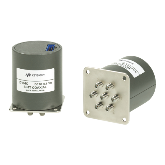
Page 11: Figure 1 L-Series Coaxial Multiport Switches - L7106C And
General Information L-Series coaxial multiport switches overview Keysight L-series coaxial multiport switches consists of two main group of products. L7104A/B/C and L7106A/B/C are terminated switches with SP4T and SP6T configuration respectively while L7204A/B/C and L7206A/B/C are unterminated SP4Ts and SP6Ts. Both terminated and unterminated L-series... -
Page 12: List Of L-Series Coaxial Multiport Switches
DC to 26.5 GHz SP4T Unterminated L7106A DC to 4 GHz SP6T Terminated L7106B DC to 20 GHz SP6T Terminated L7106C DC to 26.5 GHz SP6T Terminated L7206A DC to 4 GHz SP6T Unterminated Keysight L-Series Operating and Service Manual... -
Page 13: Drive Connection Diagram For Option 161 And Option
Each RF path can be closed by applying ground (TTL “High” for Option T24) to the corresponding “drive” pin. In general, all other RF paths are simultaneously opened by internal logic. See Figure 2 for drive connection diagrams. Figure 2 Drive connection diagram for Option 161 and Option 100 Keysight L-Series Operating and Service Manual... - Page 14 “drive” pin which corresponds to the desired RF path. – To open all RF paths, ensure that all RF path “drive” pins are disconnected from ground. Then, connect pin 16 to ground. This feature is not available in option 100. Keysight L-Series Operating and Service Manual...
- Page 15 “drive” pin which corresponds to the desired RF path. – To open all RF paths, ensure that all RF path “drive” pins are at TTL “Low”. Then, apply TTL “High” to pin. This feature is not available in option 100. Keysight L-Series Operating and Service Manual...
-
Page 16: Figure 3 Pin Function Diagram For Indicator
Table 3 for indicator specifications. The electronic position indicators require that the supply (20 to 32 VDC) be connected to pin 1 and ground connected to pin 15. Figure 3 Pin function diagram for indicator Keysight L-Series Operating and Service Manual... -
Page 17: Specifications
These are denoted as “typical”, “nominal” or “approximate” and are printed in italics. Table 2 General specifications for L-series coaxial multiport switches Keysight model number L7104A/B/C, L7106A/B/C, L7204A/B/C & L7206A/B/C Maximum power rating 1 watt average into 50 Ù internal loads – Switching W CW for terminated 2 W CW for unterminated –... -
Page 18: Rf Specifications For L710Xa And L720Xa Coaxial Multiport
< 1.70 (18 to 20 GHz) < 0.03 dB < 0.03 dB Repeatability Characteristics 50 Ω, terminated 50 Ω, unterminated Connectors SMA (f) SMA (f) [a] Up to 2 million cycles measured at 25°C Keysight L-Series Operating and Service Manual... -
Page 19: Rf Specifications For L710Xc And L720Xc Coaxial Multiport
[a] Closing one RF path required 200 mA. Add 200 mA for each additional RF path closed or opened. Using all RF paths open (selecting pin 16) requires 200 mA per RF oath reset with Vcc = 24 VDC. Keysight L-Series Operating and Service Manual... -
Page 20: Figure 4 Ttl Control Voltage States (Option T24)
TTL drive specifications for L-series coaxial multiport switches (Option T24) Nominal Unit High level input Low level input Max high input current [a] Vcc = Max, Vinput = 3.85 VDC Figure 4 TTL control voltage states (Option T24) Keysight L-Series Operating and Service Manual... -
Page 21: Figure 5 Maximum Incident Power (Cold Switching) Vs. Frequency
– Sea level (0.88 derating @15,000 feet) – Low VSWR < 1.2 (See Figure 6 for derating above 1.2 VSWR) – Power handling at 25°C is 100 W at 4 GHz Figure 5 Maximum incident power (cold switching) vs. frequency Keysight L-Series Operating and Service Manual... -
Page 22: Figure 6 Power Derating Factor Vs Vswr
Figure 6 Power derating factor vs VSWR Keysight L-Series Operating and Service Manual... -
Page 23: Environmental Specifications
Environmental Specifications The L-series coaxial multiport switches are designed to fully comply with Keysight Technologies’ product operating environmental specifications as shown in Table Table 9 L-series coaxial multiport switches environmental specifications Parameter Specification Temperature: ° ° – Operating C to +75 –... -
Page 24: L-Series Coaxial Multiport Switches Physical
Physical Specifications Table 10 L-series coaxial multiport switches physical specifications Parameter Specification Dimensions Figure 7 Net weight, kg (lb) 0.229 (0.5) Keysight L-Series Operating and Service Manual... -
Page 25: Figure 7 Dimensions Of L-Series Coaxial Multiport Switches
Figure 7 Dimensions of L-series coaxial multiport switches Keysight L-Series Operating and Service Manual... -
Page 26: Installation
Sales and Technical Support in the front matter of this manual for the Keysight Technologies nearest you. Attach a tag indicating the type of service required, return address, model number, and serial number. Mark the container FRAGILE to insure careful handling. In any correspondence, refer to the instrument by model number and serial number. -
Page 27: Figure 8 Connection To Perform Quick Check
The network analyzer may be set to sweep over the whole or selected frequency range of the switch to be verified. The s-parameters measurement is the best way to determine if the switch is working properly. Figure 8 Connection to perform quick check Keysight L-Series Operating and Service Manual... - Page 28 Refer to “TTL drive (Option T24)” on page 5. 4 Perform s-parameters measurement and verify against specifications in Table Table 5 Table 5 Repeat from step 1 until all paths are measured and verified. Keysight L-Series Operating and Service Manual...
- Page 29 The coaxial multiport switches can be tested to the accuracy of the specifications with a network analyzer or equivalent equipment of suitable accuracy. If a network analyzer is available, test the instrument using the procedure in the analyzer’s operating manual. Keysight L-Series Operating and Service Manual...
-
Page 30: Service Instructions
Maintenance The connectors, particularly the connector faces, must be kept clean. For instruction on connecting and care of your connectors, refer to the Microwave Connector Care Quick Reference Card (08510-90360). Keysight L-Series Operating and Service Manual... - Page 31 This information is subject to change without notice. Always refer to the English version at the Keysight website for the latest revision. © Keysight Technologies 2007 - 2019 Edition 3, March 27, 2019 Printed in Malaysia *L7104-90001* L7104-90001...
Need help?
Do you have a question about the L7104A and is the answer not in the manual?
Questions and answers