
Related Manuals for Keysight U7108 Series


Summary of Contents for Keysight U7108 Series
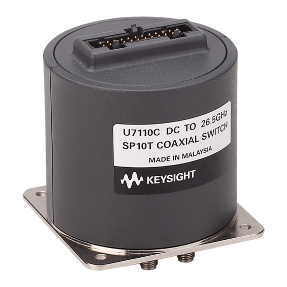
- Page 1 Keysight U7108x and U7110x Series Coaxial Multiport Switches Operating and Service Manual...
- Page 2 Declarations of Conformity for this product ceed beyond a CAUTION notice until the indi- the DFARS and are set forth specifically in and for other Keysight products may be down- cated conditions are fully understood and met. writing elsewhere in the EULA. Keysight shall loaded from the Web.
-
Page 3: Certification
Certification Keysight Technologies certifies that this product met its published specifications at the time of shipment from the factory. Keysight Technologies further certifies that its calibration measurements are traceable to the United States National Institute of Standards and Technology (NIST, formerly NBS), to the extend allowed by the Institute’s calibration facility, and to the calibration facilities of the other International Standards Organization members. -
Page 4: South Korean Class A Emc Declaration
“Monitoring and Control Instrument” product. The affixed product label is as shown below. Do not dispose in domestic household waste. To return this unwanted instrument, contact your nearest Keysight Service Center, or visit http://about.keysight.com/en/companyinfo/environment/takeback.shtml for more information. Keysight U7108x and U7110x Operating and Service Manual... -
Page 5: Sales And Technical Support
Sales and Technical Support To contact Keysight for sales and technical support, refer to the support links on the following Keysight websites: – www.keysight.com/find/switches (product-specific information and support, software and documentation updates) – www.keysight.com/find/assist (worldwide contact information for repair and service) - Page 6 THIS PAGE HAS BEEN INTENTIONALLY LEFT BLANK Keysight U7108x and U7110x Operating and Service Manual...
-
Page 7: Table Of Contents
........29 Keysight U7108x and U7110x Operating and Service Manual... - Page 8 THIS PAGE HAS BEEN INTENTIONALLY LEFT BLANK Keysight U7108x and U7110x Operating and Service Manual...
- Page 9 Connection to perform quick check ......29 Keysight U7108x and U7110x Operating and Service Manual...
- Page 10 THIS PAGE HAS BEEN INTENTIONALLY LEFT BLANK Keysight U7108x and U7110x Operating and Service Manual...
- Page 11 List of Tables Table 1-1 List of Keysight U7108x and U7110x coaxial multiport switches ..15 Table 3-1 U7108x and U7110x environmental specifications ....24...
- Page 12 THIS PAGE HAS BEEN INTENTIONALLY LEFT BLANK Keysight U7108x and U7110x Operating and Service Manual...
- Page 13 Keysight U7108x and U7110x Series Coaxial Multiport Switches Operating and Service Manual Introduction General Information Key Features This chapter provides you an overview of Keysight U7108x and U7110x series coaxial multiport switches.
-
Page 14: Introduction
Introduction General Information Keysight U7108A/B/C SP8T and U7110A/B/C SP10T terminated switches provide the life and reliability required for automated test and measurement, signal monitoring and routing applications. These switches can be used in various applications as they are available in multiple frequency ranges, up to 26.5 GHz. -
Page 15: Key Features
Introduction Table 1-1 List of Keysight U7108x and U7110x coaxial multiport switches Model number Frequency range Configuration U7108A DC to 9 GHz SP8T U7108B DC to 20 GHz SP8T U7108C DC to 26.5 GHz SP8T U7110A DC to 9 GHz... - Page 16 Introduction THIS PAGE HAS BEEN INTENTIONALLY LEFT BLANK Keysight U7108x and U7110x Operating and Service Manual...
- Page 17 Keysight U7108x and U7110x Series Coaxial Multiport Switches Operating and Service Manual Switch Configuration Driving the Switch Standard Drive (Option 200 and Option 400) TTL Drive (Option 300 and Option 500) Electronic Position Indicators This chapter provides you information on how to drive the switches using standard drive and TTL...
-
Page 18: Switch Configuration
RF path is closed (20 ms), de-select the old RF path “drive” pin while leaving the new RF path “drive” pin selected. The switch circuitry will automatically open the old RF path while leaving the new RF path engaged. Keysight U7108x and U7110x Operating and Service Manual... -
Page 19: Standard Drive (Option 200 And Option 400)
(to prevent multiple RF path engagement). Ground the “drive” pin which corresponds to the desired RF path. 4 To open all RF paths, ensure that all RF path “drive” pins are disconnected from ground. Then, connect pin 24 to ground. Keysight U7108x and U7110x Operating and Service Manual... -
Page 20: Ttl Drive (Option 300 And Option 500)
RF path engagement). Apply TTL “High” to the “drive” pin which corresponds to the desired RF path. 4 To open all RF paths, ensure that all RF path drive” pins are at TTL “Low”. Then, apply TTL “High” to pin. Keysight U7108x and U7110x Operating and Service Manual... -
Page 21: Electronic Position Indicators
AC and/or DC operation. The electronic position indicators require that the supply (24 Vdc) be connected to pin 1 and ground connected to pin 23. *Paths 1 and 6 are not connected for U7108x Figure 2-2 Pin configuration for indicator function Keysight U7108x and U7110x Operating and Service Manual... - Page 22 Switch Configuration THIS PAGE HAS BEEN INTENTIONALLY LEFT BLANK Keysight U7108x and U7110x Operating and Service Manual...
- Page 23 Keysight U7108x and U7110x Series Coaxial Multiport Switches Operating and Service Manual Specifications Environmental Specifications Physical Specifications This chapter provides you the environmental specifications of Keysight U7108x and U7110x series coaxial multiport switches.
-
Page 24: Specifications
Specifications Environmental Specifications Keysight U7108x and U7110x series coaxial multiport switches are designed to fully comply with Keysight Technologies’ product operating environmental specifications as shown in the table below. Table 3-1 U7108x and U7110x environmental specifications Temperature – Operating -25°C to +55°C –... -
Page 25: Physical Specifications
Specifications Physical Specifications The table below lists the weight of the Keysight U7108x and U7110x series coaxial multiport switches. Model number Weight U7108A/B/C 320 gms (0.705 lbs) U7110A/B/C 325 gms (0.716 lbs) Figure 3-1 Figure 3-2 show the dimensions of the Keysight U7108x and U7110x series coaxial multiport switches respectively. -
Page 26: Figure 3-2 U7110X Product Outline
Specifications Figure 3-2 U7110x product outline Keysight U7108x and U7110x Operating and Service Manual... - Page 27 Keysight U7108x and U7110x Series Coaxial Multiport Switches Operating and Service Manual Installation and Verification Installation Operating and Service Instructions This chapter provides you installation information and simple verification steps of the switches.
-
Page 28: Installation And Verification
Refer to “Sales and Technical Support” on page 5 for the Keysight office nearest to you. Attach a tag indicating the type of service required, return address, model number, and serial number. Mark the container FRAGILE to insure careful handling. -
Page 29: Operating And Service Instructions
The network analyzer may be set to sweep over the whole or selected frequency range of the switch to be verified. The S-parameter measurement is the best way to determine if the switch is working properly. Figure 4-1 Connection to perform quick check Keysight U7108x and U7110x Operating and Service Manual... - Page 30 Service instructions Adjustment and repair Keysight U7108x and U7110x series coaxial multiport switches do not require internal adjustments and are not recommended for repair. Maintenance The connectors, particularly the connector faces, must be kept clean. For instructions on connecting and care of your connectors, refer to the Microwave Connector Care Quick Reference Card (08510-90360).
- Page 31 This information is subject to change without notice. Always refer to the Keysight website for the latest revision. © Keysight Technologies 2020 Edition 1, September 4, 2020 Printed in Malaysia U7108-90001 www.keysight.com...
Need help?
Do you have a question about the U7108 Series and is the answer not in the manual?
Questions and answers