
Related Manuals for Keysight M9128A


Summary of Contents for Keysight M9128A
- Page 1 Startup Guide M9128A, M9146A, M9147A, M9148A. M9149A, M9150A, M9151A, M9152A, M9153A Keysight PXI RF Switch Modules...
- Page 3 Warranty © Keysight Technologies, Inc. 2014 No part of this manual may be repro- To contact Keysight for sales and techni- THE MATERIAL CONTAINED IN THIS duced in any form or by any means cal support, refer to the support links on DOCUMENT IS PROVIDED “AS IS,”...
- Page 4 In Case of Damage Cleaning Instruments that appear damaged or Clean the outside of the Keysight mod- defective should be made inoperative ule/chassis with a soft, lint-free, and secured against unintended oper- slightly dampened cloth. Do not use ation until they can be repaired by detergent or chemical solvents.
- Page 5 Do not dispose in domestic household nication Act of 1992. waste. Chassis Ground. To return unwanted products, contact your local Keysight office for more information. Alternating Current (AC). ICES/NMB-001 indicates that this ISM device complies with the Canadian Standby Power. Unit is not ICES-001.
-
Page 7: Table Of Contents
Power the controller ..........6 Install Keysight IO Libraries Suite ....... . . 6 Install instrument drivers . - Page 8 Keysight PXI Matrix and Multiplexer Modules Startup Guide...
-
Page 9: Keysight Pxi Rf Switch Modules Introduction
The Keysight RF switch modules deliver high-performance switching with fast, easy installation and configuration. They provide for switching frequencies beyond 300 MHz (for the M9128A Matrix module) and 3 GHz (for the Multiplexer modules). All modules exhibit low insertion loss and Voltage Standing Wave Ratio (VSWR). -
Page 10: Step 1: Unpack And Inspect The Module
Step 1: Unpack and inspect the module Step 1: Unpack and inspect the module Keysight’s PXI RF Switch Modules are shipped in materials that prevent static electricity damage. The modules should only be removed from the packaging in an anti-static area ensuring that correct anti-static precautions are taken. -
Page 11: Return The Module For Service
Step 1: Unpack and inspect the module Return the module for service Should it become necessary to return a Keysight RF Switch module for repair or service, follow the steps below: 1 Review the warranty information shipped with your product. -
Page 12: Step 2: Verify Shipment Contents
CD contains software, drivers and all product printed documentation in PDF format for the PXI RF Switch modules. - An Automation-Ready CD with Keysight IO Libraries Suite (version 16.0 or later). - Any other accessories that you ordered (cables, connectors, etc.). -
Page 13: System Requirements
Step 3: Install the software on the system controller System requirements The following table lists the minimum system requirements for Keysight IO Libraries Suite 16. In general, any x86 or x64 (except Itanium) should work but there may be a significant decrease in performance. -
Page 14: Power The Controller
4 Choose the default option for any “Found Hardware” dialogs Install Keysight IO Libraries Suite Keysight IO Libraries Suite 16.0 (or later) is required for the PXI modules. It includes the Keysight Connection Expert, the IVI Shared Components, and the VISA Shared Components. -
Page 15: Install Instrument Drivers
Virtual Instrument (IVI) driver is available for programming the Keysight switch modules using Microsoft development environments (e.g., Visual Studio, C, C++, C#, Visual Basic), Keysight VEE, MATLAB, or National Instruments LabVIEW. Accept the license terms and click Next. – Keysight Software License Agreement for drivers for use with LabVIEW Software. -
Page 16: Step 4. Connect The Pc To The Pxi Chassis
Cable Interface module in the chassis. - If you are using a desktop or rack mount PC, install the M9047A PCIe Desktop Adapter in the PC. With a Keysight Y1202A cable, connect the adapter to the System Interface module. - If you are using a laptop PC, install the M9045A PCIe ExpressCard Adapter in the laptop. -
Page 17: Step 5: Install The Switch Modules In The Pxi Chassis
- PXI hard ware does not support “hot-swap” capabilities (changing modules while power is applied to the chassis). - Before installing Keysight PXI Modules into the chassis, the chassis must be powered off to prevent damage to the PXI mod ule. Remove all cables/terminal blocks from the module prior to installing or removing the mod ule. - Page 18 If you are using a remote controller linked to the M9021A Cable Interface, you must Shut Down the PC BEFORE you power down the chassis. When you restore power, you must power up the chassis BEFORE you power up the PC. Keysight PXI RF Modules Startup Guide...
-
Page 19: Step 6. Verify Operation Of The Module
Step 6. Verify operation of the module Step 6. Verify operation of the module Run Keysight IO Libraries Connection Expert If Keysight Connection Expert is already running on the system controller, click the Refresh All button to identify any hardware you have just installed or re-connected. -
Page 20: Verify Operation
Refer to the SFP help file for additional information. Verify operation There are no specific operational verification or self test procedures. However, you can use the Soft Front Panel software to open and close individual channels. Module specifications are guaranteed by design. Keysight PXI RF Modules Startup Guide... -
Page 21: Characteristics
Com2 to Bank 2, Channel 4 M9151A, Quad 1X4, Com3 to Bank 3, Channel 4 75 Com4 to Bank 4, Channel 4 M9152A, 1X8, 75 Com to Channel 4 M9153A, 1X16, 75 Com to Channel 13 Keysight PXI RF Modules Startup Guide... -
Page 22: Module Functional Description
Module functional description Module functional description The Keysight PXI RF 50 and 75 switch modules conform to the single slot, 3U form factor (100mm by 160mm / 3.94 in. by 6.3 in.) Eurocard standard. These modules meet PXI Specification 2.2. Local bus, trigger bus, and star trigger are not included. -
Page 23: Module Programming
In the Soft Front Panel interface, when you mouse over a specific channel or crosspoint (M9128A Matrix) the cursor changes to a hand cursor, and a popup tool tip shows the Instrument Specific Syntax for the channel number as shown in the following graphics. -
Page 24: Module Front Panel Connectors And System Connections
Module front panel connectors and system connections For the M9128A Matrix module, the Instrument Specific Syntax for channel numbers uses the form: mnrncn where m indicates a matrix module, rn is the row and cn is the column. For example, RouteCloseChannel(“m1r2c3”) will close the relays to connect row 2 to column 3 of matrix 1. -
Page 25: M9128A Pxi Rf Matrix Switch: 300 Mhz, 8X12, 50W
Module front panel connectors and system connections M9128A PXI RF Matrix Switch: 300 MHz, 8x12, 50 The M9128A Matrix module provides isolation switches, located on all coaxial connectors, to disconnect the matrix crosspoint switches. Only the signal is switched, all grounds are common. While the module is an 8X12 matrix, it is formed by joining four separate 4X6 matrices using isolation relays (see the figure below). - Page 26 Note that while multiple crosspoints may be closed in any row or column, significant RF performance degradation will occur. For detailed specifications, refer to the M9128A datasheet on the Switch Module Software and Product Information CD or the RF Switch data sheet online at www.keysight.com/find/pxiswitch.
-
Page 27: M9146A Pxi Rf Multiplexer Module: 3 Ghz, Dual 1X4, 50W Terminated19
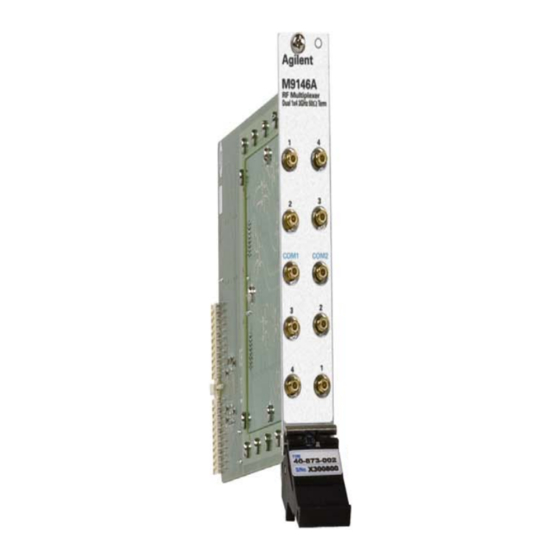
Module front panel connectors and system connections M9146A PXI RF Multiplexer Module: 3 GHz, Dual 1x4, 50 Terminated Keysight's M9146A Dual 1x4 50 Multiplexer Module exhibits low insertion loss and VSWR. The module is constructed as two separate 1X4 RF switch multiplexers. -
Page 28: M9147A Pxi Rf Multiplexer: 3 Ghz, Quad 1X4, 50W Terminated Common
Module front panel connectors and system connections M9147A PXI RF Multiplexer: 3 GHz, Quad 1x4, 50 Terminated Common Keysight's M9147A Dual 1x4 50 Multiplexer Module exhibit low insertion loss and VSWR. The module is constructed as four separate 1X4 multiplexers. The default state of the common relay is terminated in a 50... -
Page 29: M9148A Pxi Rf Multiplexer: 3 Ghz, 1X8, 50W
Module front panel connectors and system connections M9148A PXI RF Multiplexer: 3 GHz, 1x8, 50 Keysight's M9148A 1x8 50 Multiplexer Module exhibits low insertion loss and VSWR. This module features excellent insertion loss and VSWR for better RF signal integrity as well as outstanding dynamic range for routing RF signals into your measurement equipment. -
Page 30: M9149A Pxi High Density Rf Multiplexer: 3 Ghz, 1X16, 50W
Module front panel connectors and system connections M9149A PXI High Density RF Multiplexer: 3 GHz, 1x16, 50 Keysight's M9149A 1x16 50 Multiplexer Module exhibits low insertion loss and VSWR. This module features excellent insertion loss and VSWR for better RF signal integrity as well as outstanding dynamic range for routing RF signals into your measurement equipment. -
Page 31: M9150A Pxi Rf Multiplexer: 3 Ghz, Dual 1X4, 75W
Module front panel connectors and system connections M9150A PXI RF Multiplexer: 3 GHz, Dual 1X4, 75 Keysight's M9150A Dual 1x4 75 Multiplexer Module exhibit low insertion loss and VSWR. The module is constructed as four separate 1X4 multiplexers. The 75 inputs make it ideal for routing video RF signals. Each path is carefully designed to ensure repeatable RF performance. -
Page 32: M9151A Pxi Rf Multiplexer: 3 Ghz, Quad 1X4, 75W
Module front panel connectors and system connections M9151A PXI RF Multiplexer: 3 GHz, Quad 1X4, 75 Keysight's M9151A quad 1x4 75 Multiplexer Module exhibit low insertion loss and VSWR. The module is constructed as four separate 1X4 multiplexers as shown in the diagram below. The 75 inputs make it ideal for routing video RF signals. -
Page 33: M9152A Pxi Rf Multiplexer: 3 Ghz, 1X8, 75W
Module front panel connectors and system connections M9152A PXI RF Multiplexer: 3 GHz, 1X8, 75 Keysight's M9152A 1x8 75 Multiplexer Module exhibits low insertion loss and VSWR. The 75 inputs make it ideal for routing video RF signals. Each path is carefully designed to ensure repeatable RF performance. -
Page 34: M9153A Pxi Rf Multiplexer: 3 Ghz, 1X16, 75W
Module front panel connectors and system connections M9153A PXI RF Multiplexer: 3 GHz, 1X16, 75 Keysight's M9153A 1x16 75 Multiplexer Module exhibits low insertion loss and VSWR. The 75 inputs make it ideal for routing video RF signals. Each path is carefully designed to ensure repeatable RF performance. - Page 35 For other unlisted Countries: www.keysight.com/find/contactus LAN eXtensions for instruments puts the power of Ethernet and the Web inside your test systems. Keysight is a founding member of the LXI consortium. www.pxisa.org PCI eXtensions for Instrumentation (PXI) modular instrumentation delivers a rugged PC-based high-performance measurement and automation platform.
- Page 36 This information is subject to change without notice. © Keysight Technologies, 2014 Edition 2 December 2014 *M9128-90001* M9128-90001 www.keysight.com...
Need help?
Do you have a question about the M9128A and is the answer not in the manual?
Questions and answers