Table of Contents
Advertisement
Quick Links
TABLE OF CONTENTS
1 Safety Precautions----------------------------------------------- 3
2 Specifications ----------------------------------------------------- 5
2.1. CS-PC36HKV CU-PC36HKV-------------------------- 5
3 Features ------------------------------------------------------------- 7
4 Location of Controls and Components ------------------- 8
4.1. Indoor Unit--------------------------------------------------- 8
4.2. Outdoor Unit ------------------------------------------------ 8
4.3. Remote Control -------------------------------------------- 8
5 Dimensions--------------------------------------------------------- 9
5.1. Indoor Unit & Remote Control -------------------------- 9
5.2. Outdoor Unit -----------------------------------------------10
6 Refrigeration Cycle Diagram --------------------------------11
7 Block Diagram----------------------------------------------------12
8 Wiring Connection Diagram ---------------------------------13
Indoor Unit
CS-PC36HKV CU-PC36HKV
PAGE
9 Electronic Circuit Diagram----------------------------------- 14
9.1. CS-PC36HKV --------------------------------------------- 14
9.2. CU-PC36HKV--------------------------------------------- 15
10 Printed Circuit Board ------------------------------------------ 16
10.1. Indoor Unit ------------------------------------------------- 16
10.2. Outdoor Unit----------------------------------------------- 17
10.3. Indicator ---------------------------------------------------- 18
11 Installation Instruction ---------------------------------------- 19
11.1. Select The Best Location ------------------------------ 19
11.2. Indoor/Outdoor UnitInstallation Diagram ----------- 19
11.3. Indoor Unit ------------------------------------------------- 20
11.4. Outdoor Unit----------------------------------------------- 24
12 Operation Control----------------------------------------------- 28
12.1. Cooling Operation---------------------------------------- 28
© 2008 Panasonic HA Air-Conditioning (M) Sdn Bhd
(11969-T). All rights reserved. Unauthorized copying
and distribution is a violation of law.
Order No. MAC0802018C3
Air Conditioner
Outdoor Unit
PAGE
Advertisement
Table of Contents

Related Manuals for Panasonic CS-PC36HKV


Summary of Contents for Panasonic CS-PC36HKV
-
Page 1: Table Of Contents
11.4. Outdoor Unit----------------------------------------------- 24 7 Block Diagram----------------------------------------------------12 12 Operation Control----------------------------------------------- 28 8 Wiring Connection Diagram ---------------------------------13 12.1. Cooling Operation---------------------------------------- 28 © 2008 Panasonic HA Air-Conditioning (M) Sdn Bhd (11969-T). All rights reserved. Unauthorized copying and distribution is a violation of law. - Page 2 12.2. Soft Dry Operation --------------------------------------- 28 12.3. Auto Operation-------------------------------------------- 28 12.4. Fan Operation--------------------------------------------- 29 12.5. Thermostat Control -------------------------------------- 29 12.6. Indoor Fan Control --------------------------------------- 29 12.7. Odour Cut Control---------------------------------------- 29 12.8. Vertical Airflow Direction Control --------------------- 30 12.9. Horizontal Airflow Direction Control ----------------- 30 12.10.
-
Page 3: Safety Precautions
1 Safety Precautions • Read the following “SAFETY PRECAUTIONS” carefully before perform any servicing. • Electrical work must be installed or serviced by a licensed electrician. Be sure to use the correct rating of the power plug and main circuit for the model installed. •... - Page 4 Carry out drainage piping as mentioned in installation instructions. If drainage is not perfect, water may enter the room and damage the furniture. Pb free solder has a higher melting point than standard solder; typically the melting point is 50 - 70°F (30 - 40°C) higher. Please use a high temperature soldering iron.
-
Page 5: Specifications
2 Specifications 2.1. CS-PC36HKV CU-PC36HKV Item Unit Indoor unit Outdoor unit Performance Test Condition NEW JIS Capacity 10.55 BTU/h 36000 *kJ/h 37980 2.93 BTU/hW 10.0 Noise Level dB (A) High: 50 Low: 45 High: 55 / - Power level dB —... - Page 6 Item Unit Power Source (Phase, Voltage, Cycle) ø Single Input power 3.60 Starting Current Running Current Cooling 17.5 Maximum Current 21.8 Power Factor Cooling Power factor means total figure of compressor, indoor fan motor and outdoor fan motor. Power Cord Number of core —...
-
Page 7: Features
3 Features • Long Installation Piping - CS/CU-PC36HKV, long piping up to 30 meter. • Easy to use remote control • Quality Improvement - Random auto restart after power failure for safety restart operation. - Gas leakage detection. - Prevent compressor reverse cycle. - Inner protector to protect compressor. -
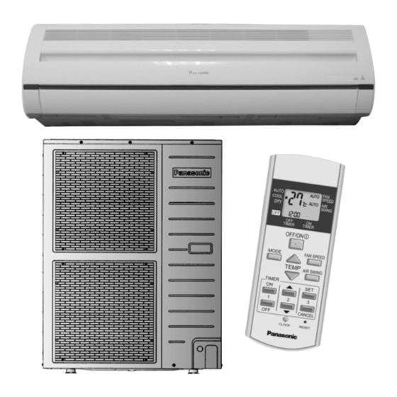
Page 8: Location Of Controls And Components
4 Location of Controls and Components 4.1. Indoor Unit 4.2. Outdoor Unit • Outdoor unit shown is CU-PC36HK. 4.3. Remote Control... -
Page 9: Dimensions
5 Dimensions 5.1. Indoor Unit & Remote Control 5.1.1. CS-PC36HKV... -
Page 10: Outdoor Unit
5.2. Outdoor Unit 5.2.1. CU-PC36HKV... -
Page 11: Refrigeration Cycle Diagram
6 Refrigeration Cycle Diagram... -
Page 12: Block Diagram
7 Block Diagram... -
Page 13: Wiring Connection Diagram
8 Wiring Connection Diagram... -
Page 14: Electronic Circuit Diagram
9 Electronic Circuit Diagram 9.1. CS-PC36HKV... -
Page 15: Cu-Pc36Hkv
9.2. CU-PC36HKV... -
Page 16: Printed Circuit Board
10 Printed Circuit Board 10.1. Indoor Unit... -
Page 17: Outdoor Unit
10.2. Outdoor Unit... -
Page 18: Indicator
10.3. Indicator... -
Page 19: Installation Instruction
11 Installation Instruction 11.1. Select The Best Location 11.2. Indoor/Outdoor Unit Installation Diagram 11.1.1. Indoor Unit • Do not install the unit in excessive oil fume area such as kitchen, workshop and etc. • There should not be any heat source or steam near the unit. •... -
Page 20: Indoor Unit
11.3. Indoor Unit 11.3.1. How To Fix Installation Plate 11.3.2. To Drill A Hole In The Wall And The mounting wall is strong and solid enough to prevent it from Install A Sleeve Of Piping the vibration. 1. Insert the piping sleeve to the hole. 2. - Page 21 11.3.3.3. For the embedded piping 3. Set the piping direction. (For bottom piping, need to perform cutting and flaring process.) 4. Use 2 spanner to tighten the nut. (tighten torque 65 N Install accessory of tube ass’y 1. Remove chassis back particular piece. 5.
- Page 22 (This can be used for left rear piping and left bottom piping also.)
- Page 23 11.3.4. Connect The Cable To The Indoor Unit 1. The indoor and outdoor connecting cable can be connected without removing the front grille. 2. Connecting cable between indoor unit and outdoor unit shall be approved polychloroprene sheathed 4 × 1.5 mm flexible cord, type designation 245 IEC 57 or heavier cord.
-
Page 24: Outdoor Unit
11.4. Outdoor Unit 11.4.1. Install The Outdoor Unit • After selecting the best location, start installation according to Indoor/Outdoor Unit Installation Diagram. 1. If installing the unit to a concrete base or other solid base, use M10 or W3/8 bolts and nuts to secure the unit, and ensure that the unit is fully upright and level. - Page 25 11.4.2.3. Cutting And Flaring The Piping 1. Please cut using pipe cutter and then remove the burrs. 2. Remove the burrs by using reamer. If burrs is not removed, gas leakage may be caused. Turn the piping end down to avoid the metal powder entering the pipe. 3.
- Page 26 2) Air Purging The air remaining in the Refrigeration cycle which contains moisture may cause malfunction on the Compressor. 1. To purge the air, push the pin on the Gas side 3-way valve for three seconds with a Hexagonal wrench and set it free for one minute.
- Page 27 11.4.5. Pipe Insulation 1. Please carry out insulation at pipe connection portion as mentioned in Indoor/Outdoor Unit Installation Diagram. Please wrap the insulated piping end to prevent water from going inside the piping. 2. If drain hose or connecting piping is in the room (where dew may form), please increase the insulation by using POLY-E FOAM with thickness 6mm or above.
-
Page 28: Operation Control
12 Operation Control 12.1. Cooling Operation • Cooling operation can be set using remote control. • This operation is applied to cool down the room temperature reaches the setting temperature set on the remote control. • Cooling Operation Time Diagram. 12.2. -
Page 29: Fan Operation
12.4. Fan Operation • Fan operation can be set using remote control. • The indoor fan is operated at High, Medium or Low speed according to remote control setting. 12.5. Thermostat Control • Depending on differences between room temperature and setting temperature, compressor operation is decided and starts operation. -
Page 30: Vertical Airflow Direction Control
12.8. Vertical Airflow Direction Control Auto Control • When the vertical airflow direction is set to Auto using the remote control, the louver swings up and down as shown in the diagram. • When stop operation using the remote control, the discharge vent is reset, and stop at the closing position. •... -
Page 31: Outdoor Fan Control
12.10. Outdoor Fan Control • Outdoor fan speed changes according to outdoor pipe temperature. •The fan speed is controlled by the timing of turning the outdoor fan ON and OFF within an interval. •There unit compares current temperature (T2) with previous (2 seconds before) temperature (T1) and decides the outdoor fan ON time (X). -
Page 32: Protection Control
13 Protection Control 13.1. Freeze Prevention Control • After compressor starts operation for 4 minutes, the outdoor unit will stop its operation if indoor pipe temperature falls below 2ºC for 6 minutes. • After 3 minutes stops, compressor restarts operation if indoor pipe temperature is 3ºC or more. •... -
Page 33: Test Run (Forced Cooling Mode)
13.3. Test Run (Forced Cooling mode) • Test run is necessary after installation is completed. • To enable test run operation, at outdoor PCB, set the DS1 Switch 1 to ON position. • Press Test Run button for 1 second. 13.3.1. -
Page 34: Pump Down
13.4. Pump down • To enable pump down operation, at outdoor PCB, set the DS1 to OFF position. • Press Test Run button for 1 second. • During Pump Down operation, push the Test Run button again for 1 second to stop the pump down operation. •... -
Page 35: Servicing Mode
14 Servicing Mode 14.1. Auto OFF/ON Button • The “Auto OFF/ON Button” (behind the front grille) is used to operate the air conditioner if remote control is misplaced or malfunctioning. • Forced cooling operation is possible by pressing the “Auto OFF/ON Button” for more than 5s where “beep” sound is heard then release the button. -
Page 36: Test Mode Timer Table
14.2.2. CLOCK • To change the remote control’s clock-hour and minute. - Press once to enter the clock setting mode. - Use timer increment button timer decrement button to change the time. - Press once again to exit the setting mode. •... -
Page 37: Troubleshooting Guide
15 Troubleshooting Guide 15.1. Refrigeration Cycle System In order to diagnose malfunctions, make sure that there are no electrical problems before inspecting the refrigeration cycle. Such problems include insufficient insulation, problem with the power source, malfunction of a compressor and a fan. The normal outlet air temperature and pressure of the refrigeration cycle depends on various conditions, the standard values for them are shown in the table on the right. -
Page 38: Relationship Between The Condition Of The Air Conditioner And Pressure And Electric Current
15.2. Relationship Between The Condition Of The Air Conditioner And Pressure And Electric Current Cooling Mode Condition of the air conditoner Low Pressure High Pressure Electric current during operation Insufficient refrigerant (gas leakage) Clogged capillary tube or Strainer Short circuit in the indoor unit Heat radiation deficiency of the outdoor unit Inefficient compression... -
Page 39: Error Code Table
15.4. Error Code Table 15.4.1. Self-diagnosis function 1. The self-diagnosis LEDs (red) on the outdoor unit printed circuit board can be used to indicate where the location of a problem Refer to the table below to remove the cause of the problem and then re-start the air conditioner system. 2. - Page 40 15.4.2. About the test operation • Test operation can be carried out using the remote control unit or by using the switch on the printed circuit board inside the outdoor unit. • If carrying out test operation at the printed circuit board of the outdoor unit, follow the procedure given below. (If using the remote control unit to carry out test operation, refer to the installation manual which is supplied with the indoor unit.) •...
-
Page 41: Disassembly And Assembly Instructions
16 Disassembly and Assembly Instructions WARNING • Cautions! When handling electronic controller, be careful of electrostatic discharge. • Be sure to return the wiring to its original position. • There are many high voltage components within the heat sink cover so never touch the interior during operation. Wait at least two minutes after power has been turned off. - Page 42 • Release the taps on the top, on the left and on the right side of Control Board Front Cover. (Fig. 3) • Then remove the Control Board Front Cover. (Fig. 3) • How to remove PCBs from the control board. - Remove the Indicator Complete.
- Page 43 • Pull down the Discharge Grille Complete. (Fig. 7) • Remove the earth wire from the evaporator. (Fig. 8) • Remove 2 screws on the left and right side of the control board. (Fig. 8) • Then pull out the control board from the unit. (Fig.8)
- Page 44 • Remove the cross flow fan bushing from the chassis. (Fig. 9) • Remove the screws on the left side of evaporator. (Fig. 9) • Loosen the fan boss screw at the cross flow fan. (Fig. 9) • Push up the evaporator and remove cross flow fan by pulling both cross flow fan and fan motor. (Fig. 10)
-
Page 45: Technical Data
17 Technical Data 17.1. Thermostat Characteristics Cooling Soft Dry... -
Page 46: Operation Characteristics
17.2. Operation Characteristics 17.2.1. CS-PC36HKV CU-PC36HKV... -
Page 48: Exploded View And Replacement Parts List
18 Exploded View and Replacement Parts List 18.1. Indoor Unit Note: The above exploded view is for the purpose of parts disassembly and replacement. The non-numbered parts are not kept as standard service parts. - Page 49 <Model: CS-PC36HKV> REF. NO. PART NAME & DESCRIPTION QTY. CS-PC36HKV REMARKS CHASSY COMPLETE CWD50C1477 FAN MOTOR DC 60W 3PH ARW42A8P60AC CROSS FLOW FAN COMPLETE CWH02C1044 SCREW - CROSS FLOW FAN CWH551146 BEARING ASS’Y CWH64K007 EVAPORATOR COMPLETE CWB30C2533 TUBE ASS'Y COM CWT01C3637 FLARE NUT (3/8”)
-
Page 50: Outdoor Unit
18.2. Outdoor Unit 18.2.1. CU-PC36HKV... - Page 52 Note: The above exploded view is for the purpose of parts disassembly and replacement. The non-numbered parts are not kept as standard service parts.
- Page 53 <Model: CU-PC36HKV> REF. NO. PART NAME & DESCRIPTION QTY. CU-PC36HKV REMARKS BASE PAN ASS’Y CWD52K1157 COMPRESSOR ZR40K3-PFV-512 ANTI - VIBRATION BUSHING CWH501020 PACKING CWB811017 NUT FOR COMP. MOUNT. CWH561049 CONDENSER COMPLETE CWB32C2345 TUBE ASS’Y (EXP. VALVE + STRAINER) CWT01C4494 3-WAYS VALVE (LIQUID) CWB011295 STRAINER CWB111032...
Need help?
Do you have a question about the CS-PC36HKV and is the answer not in the manual?
Questions and answers