Table of Contents
Advertisement
TABLE OF CONTENTS
1 Safety Precautions----------------------------------------------- 3
2 Specifications ----------------------------------------------------- 5
3 Features ------------------------------------------------------------- 7
4 Location of Controls and Components ------------------- 8
4.1. Indoor Unit--------------------------------------------------- 8
4.2. Outdoor Unit ------------------------------------------------ 8
4.3. Remote Control -------------------------------------------- 8
5 Dimensions--------------------------------------------------------- 9
5.1. Indoor Unit & Remote Control -------------------------- 9
5.2. Outdoor Unit -----------------------------------------------10
6 Refrigeration Cycle Diagram --------------------------------11
7 Block Diagram----------------------------------------------------12
8 Wiring Connection Diagram ---------------------------------13
8.1. Indoor Unit--------------------------------------------------13
Indoor Unit
CS-PC36JKV CU-PC36JKV
PAGE
8.2. Outdoor Unit----------------------------------------------- 13
9 Electronic Circuit Diagram----------------------------------- 14
9.1. Indoor Unit ------------------------------------------------- 14
9.2. Outdoor Unit----------------------------------------------- 15
10 Printed Circuit Board ------------------------------------------ 16
10.1. Indoor Unit ------------------------------------------------- 16
10.2. Outdoor Unit----------------------------------------------- 18
11 Installation Instruction ---------------------------------------- 19
11.1. Select The Best Location ------------------------------ 19
11.2. Indoor/Outdoor UnitInstallation Diagram ----------- 19
11.3. Indoor Unit ------------------------------------------------- 20
11.4. Outdoor Unit----------------------------------------------- 24
12 Operation Control----------------------------------------------- 29
12.1. Cooling Operation---------------------------------------- 29
© Panasonic HA Air-Conditioning (M) Sdn. Bhd. 2008.
Unauthorized copying and distribution is a violation of law.
Order No. PHAAM0810074C2
Air Conditioner
Outdoor Unit
PAGE
Advertisement
Table of Contents

Subscribe to Our Youtube Channel
Related Manuals for Panasonic CS-PC36JKV


Summary of Contents for Panasonic CS-PC36JKV
-
Page 1: Table Of Contents
7 Block Diagram----------------------------------------------------12 11.4. Outdoor Unit----------------------------------------------- 24 12 Operation Control----------------------------------------------- 29 8 Wiring Connection Diagram ---------------------------------13 8.1. Indoor Unit--------------------------------------------------13 12.1. Cooling Operation---------------------------------------- 29 © Panasonic HA Air-Conditioning (M) Sdn. Bhd. 2008. Unauthorized copying and distribution is a violation of law. - Page 2 12.2. Soft Dry Operation --------------------------------------- 29 12.3. Auto Operation-------------------------------------------- 29 12.4. Thermostat Control -------------------------------------- 30 12.5. Indoor Fan Control --------------------------------------- 30 12.6. Outdoor Fan Operation --------------------------------- 30 12.7. Odour Cut Control---------------------------------------- 31 12.8. Vertical Airflow Direction Control --------------------- 31 12.9. Horizontal Airflow Direction Control ----------------- 31 13 Protection Control ---------------------------------------------- 32 13.1.
-
Page 3: Safety Precautions
1. Safety Precautions • Read the following “SAFETY PRECAUTIONS” carefully before perform any servicing. • Electrical work must be installed or serviced by a licensed electrician. Be sure to use the correct rating of the power plug and main circuit for the model installed. •... - Page 4 WARNING 20. After completion of installation or service, confirm there is no leakage or refrigerant gas. It may generate toxic gas when the refrigerant contacts with fire. 21. Ventilate if there is refrigerant gas leakage during operation. It may cause toxic gas when refrigerant contacts with fire. 22.
-
Page 5: Specifications
2 Specifications MODEL INDOOR CS-PC36JKV OUTDOOR CU-PC36JKV Performance Test Condition NEW JIS Phase, Hz Single, 60 Power Supply 10.55 Capacity BTU/h 36000 kJ/h 37980 Running Current 17.5 Input Power 3600 2.93 Btu/hW 10.00 Power Factor dB-A 50 / 45 Indoor Noise (H / L ) Power Level dB —... - Page 6 MODEL INDOOR CS-PC36JKV OUTDOOR CU-PC36JKV Inner Diameter Drain Hose Length Fin Material Aluminium (Pre Coat) Fin Type Corrugate Fin Indoor Heat Row u Stage u 2 u 14 u 17 Exchanger Size (W u H u L) 44 u 355.6 u 880...
-
Page 7: Features
3 Features • Long Installation Piping - Long piping up to 30 meter. • Easy to use remote control • Quality Improvement - Random auto restart after power failure for safety restart operation. - Gas leakage detection. - Prevent compressor reverse cycle. - Inner protector to protect compressor. -
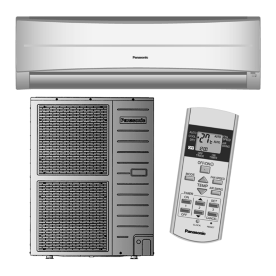
Page 8: Location Of Controls And Components
4 Location of Controls and Components 4.1. Indoor Unit 4.2. Outdoor Unit • Outdoor unit shown is CU-PC36JK. 4.3. Remote Control... -
Page 9: Dimensions
5 Dimensions 5.1. Indoor Unit & Remote Control... -
Page 10: Outdoor Unit
5.2. Outdoor Unit... -
Page 11: Refrigeration Cycle Diagram
6 Refrigeration Cycle Diagram... -
Page 12: Block Diagram
7 Block Diagram... -
Page 13: Wiring Connection Diagram
8 Wiring Connection Diagram 8.1. Indoor Unit 8.2. Outdoor Unit... -
Page 14: Electronic Circuit Diagram
9 Electronic Circuit Diagram 9.1. Indoor Unit... -
Page 15: Outdoor Unit
9.2. Outdoor Unit... -
Page 16: Printed Circuit Board
10 Printed Circuit Board 10.1. Indoor Unit 10.1.1. Main Printed Circuit Board... - Page 17 10.1.2. Power Printed Circuit Board 10.1.3. Indicator Printed Circuit Board...
-
Page 18: Outdoor Unit
10.2. Outdoor Unit 10.2.1. Main Printed Circuit Board... -
Page 19: Installation Instruction
11 Installation Instruction 11.1. Select The Best Location 11.2. Indoor/Outdoor Unit Installation Diagram 11.1.1. Indoor Unit • Do not install the unit in excessive oil fume area such as kitchen, workshop and etc. • There should not be any heat source or steam near the unit. •... -
Page 20: Indoor Unit
11.3. Indoor Unit 11.3.1. How To Fix Installation Plate 11.3.2. To Drill A Hole In The Wall And The mounting wall is strong and solid enough to prevent it from Install A Sleeve Of Piping the vibration. 1. Insert the piping sleeve to the hole. 2. - Page 21 11.3.3.3. For the embedded piping Install accessory of tube ass’y 1. Remove chassis back particular piece.
- Page 22 7. Close back the chassis back piece. 2. Connect tube ass’y to gas side piping. Liquid side piping need to pull out to joint tube ass’y. 3. Set the piping direction. (For bottom piping, need to perform cutting and flaring process.) (This can be used for left rear piping and left bottom piping also.)
-
Page 23: Connect The Cable To The Indoor Unit
11.3.4. Connect The Cable To The Indoor Unit 1. The indoor and outdoor connecting cable can be connected without removing the front grille. 2. Connecting cable between indoor unit and outdoor unit shall be approved polychloroprene sheathed 4 u 2.5 mm flexible cord, type designation 245 IEC 57 or heavier cord. -
Page 24: Outdoor Unit
11.4. Outdoor Unit 11.4.1. Install The Outdoor Unit • After selecting the best location, start installation according to Indoor/Outdoor Unit Installation Diagram. 1. If installing the unit to a concrete base or other solid base, use M10 or W3/8 bolts and nuts to secure the unit, and ensure that the unit is fully upright and level. - Page 25 11.4.2.2. Connecting The Piping To Outdoor Unit Decide piping length and then cut by using pipe cutter. Remove burrs from cut edge. Make flare after inserting the flare nut (locate at valve) onto the copper pipe. Align center of piping to valves and then tighten with torque wrench to the specified torque as stated in the table.
- Page 26 11.4.3. Air Purging Of The Pipings And Indoor Unit 1) Checking a gas leakage 1. Remove the service port cap from 3-way valves. 2. Connect the Manifold gauge set to the service port of liquid side 3-way valve. 3. Connect the Charging Cylinder to the Manifold gauge set and open the valve of the Cylinder. 4.
-
Page 27: Connect The Cable To The Outdoor Unit
11.4.4. Connect The Cable To The Outdoor Unit (FOR DETAIL REFER TO WIRING DIAGRAM AT UNIT) 1. Remove the control board cover from the unit by loosening the screw. 2. Connecting cable between indoor unit and outdoor unit shall be approved polychloroprene sheathed 4 x 2.5 mm flexible cord, type designation 245 IEC 57 or heavier cord. - Page 28 11.4.6. Precautions with Regard to Test Operation • Use only insulation tool to switch on the microswitch on the electric circuit board (do not use finger or metallic tool). • Do not switch on power before all installation is completed. •...
-
Page 29: Operation Control
12 Operation Control 12.1. Cooling Operation • Cooling operation can be set using remote control. • This operation is applied to cool down the room temperature reaches the setting temperature set on the remote control. • Cooling Operation Time Diagram. 12.2. -
Page 30: Thermostat Control
12.4. Thermostat Control • Depending on differences between room temperature and setting temperature, compressor operation is decided and starts operation. • If temperature difference matches values shown below, thermostat switches off. Cooling Soft Dry -1.0qC 12.5. Indoor Fan Control 12.5.1. Manual Fan Speed •... -
Page 31: Odour Cut Control
12.7. Odour Cut Control • Odour cut operation removes the odour generated at indoor heat exchanger by using drain water come out from indoor heat exchanger. • Press “Odour” button at remote control to enable odour cut operation. • Odour cut operation starts when compressor or thermostat is on. Thermostat &... -
Page 32: Protection Control
13 Protection Control 13.1. Restart Control (Time Delay Safety Control) • When the thermo-off temperature (temperature which compressor stops to operate) is reached, the compressor stops for 3 minutes (minimum) before resume operation. • If the operation is stopped by the remote control, the compressor will not turn on within 3 minutes from the moment operation stop, although the unit is on again within the period. -
Page 33: Outdoor Fan Residual Heat Removal Control
• Dew prevention control will be cancel when: - Any one of the condition above does not comply. 13.4. Outdoor Fan Residual Heat Removal Control • When the compressor stops to operate, the outdoor fan motor continue to operate for 60 seconds before stops operation. •... -
Page 34: Servicing Mode
14 Servicing Mode 14.1. Auto OFF/ON Button 1. AUTO OPERATION MODE The Auto operation will be activated immediately once the AUTO OFF/ON button is pressed. This operation can be used to operate air conditioner with limited function if remote control is misplaced or malfunction. 2. -
Page 35: Remote Control Button
After AUTO OFF/ON button is pressed, the 20 seconds counter for Remote Control Receiving Sound OFF/ON mode is restarted. 14.2. Remote Control Button 14.2.1. SET • To change the type of remote control transmission signal (there are totally four types of transmission codes). - Modify the jumper (back of PCB) &... -
Page 36: Troubleshooting Guide
15 Troubleshooting Guide 15.1. Refrigeration Cycle System In order to diagnose malfunctions, make sure that there are no electrical problems before inspecting the refrigeration cycle. Such problems include insufficient insulation, problem with the power source, malfunction of a compressor and a fan. The normal outlet air temperature and pressure of the refrigeration cycle depends on various conditions, the standard values for them are shown in the table on the right. -
Page 37: Relationship Between The Condition Of The Air Conditioner And Pressure And Electric Current
15.2. Relationship Between The Condition Of The Air Conditioner And Pressure And Electric Current Cooling Mode Condition of the air conditoner Low Pressure High Pressure Electric current during operation Insufficient refrigerant (gas leakage) Clogged capillary tube or Strainer Short circuit in the indoor unit Heat radiation deficiency of the outdoor unit Inefficient compression... -
Page 38: Error Code Table
15.4. Error Code Table 15.4.1. Self-diagnosis function 1. The self-diagnosis LEDs (red) on the outdoor unit printed circuit board can be used to indicate where the location of a problem Refer to the table below to remove the cause of the problem and then re-start the air conditioner system. 2. -
Page 39: Test Run (Forced Cooling Control)
15.5. Test Run (Forced Cooling Control) • Test Run can be enable using the switch at the outdoor unit's PCB according to procedure below: - Set the DS1 to (Cooling Test Run) mode - Press SW1 for 1 second to test run. - Be sure to select cooling mode first, and run the unit in this mode for 5 minutes or more. -
Page 40: Disassembly And Assembly Instructions
16 Disassembly and Assembly Instructions WARNING High Voltage are generated in the electrical parts area by the capacitor. Ensure that the capacitor has discharged sufficiently before proceeding with repair work. Failure to heed this caution may result in electric shocks. 16.1. - Page 41 16.1.3. To remove discharge grille...
- Page 42 16.1.4. To remove control board 16.1.5. To remove cross flow fan and indoor fan motor...
-
Page 44: Technical Data
17 Technical Data 17.1. Thermostat Characteristics Cooling Soft Dry... -
Page 45: Operation Characteristics
17.2. Operation Characteristics... -
Page 47: Exploded View And Replacement Parts List
18 Exploded View and Replacement Parts List 18.1. Indoor Unit Note: The above exploded view is for the purpose of parts disassembly and replacement. The non-numbered parts are not kept as standard service parts. - Page 48 REF. NO. PART NAME & DESCRIPTION QTY. CS-PC36JKV REMARKS CHASSY COMPLETE CWD50C1477 FAN MOTOR DC 60W 3PH ARW42A8P60AC CROSS FLOW FAN COMPLETE CWH02C1044 SCREW - CROSS FLOW FAN CWH551146 BEARING ASS’Y CWH64K007 EVAPORATOR COMPLETE CWB30C2533 TUBE ASS'Y COM (EVA) CWT01C3637 FLARE NUT (3/8”)
-
Page 49: Outdoor Unit
18.2. Outdoor Unit... - Page 51 Note: The above exploded view is for the purpose of parts disassembly and replacement. The non-numbered parts are not kept as standard service parts.
- Page 52 REF. NO. PART NAME & DESCRIPTION QTY. CU-PC36JKV REMARKS BASE PAN ASS’Y CWD52K1157 COMPRESSOR ZR40K3-PFV-512 ANTI - VIBRATION BUSHING CWH501020 GASKET FOR TERMINAL COVER CWB811017 NUT FOR COMP. MOUNT. CWH561049 CONDENSER COMPLETE CWB32C2345 TUBE ASS’Y (EXP. VALVE + STRAINER) CWT01C4494 3-WAYS VALVE (GAS) CWB011295 STRAINER...
Need help?
Do you have a question about the CS-PC36JKV and is the answer not in the manual?
Questions and answers