Table of Contents
Advertisement
Quick Links
TABLE OF CONTENTS
1 Safety Precautions----------------------------------------------- 3
2 Specifications ----------------------------------------------------- 5
3 Features ------------------------------------------------------------- 7
4 Location of Controls and Components ------------------- 8
4.1. Indoor Unit--------------------------------------------------- 8
4.2. Outdoor Unit ------------------------------------------------ 8
4.3. Remote Control -------------------------------------------- 8
5 Dimensions--------------------------------------------------------- 9
5.1. Indoor Unit & Remote Control -------------------------- 9
5.2. Outdoor Unit -----------------------------------------------10
6 Refrigeration Cycle Diagram --------------------------------11
7 Block Diagram----------------------------------------------------12
8 Wiring Connection Diagram ---------------------------------13
9 Electronic Circuit Diagram -----------------------------------14
10 Printed Circuit Board-------------------------------------------15
10.1. Indoor Unit--------------------------------------------------15
10.2. Indicator Printed Circuit Board ------------------------16
11 Installation Instruction-----------------------------------------17
11.1. Select The Best Location -------------------------------17
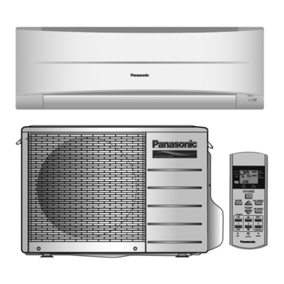
Indoor Unit
CS-PC12JKF CU-PC12JKF
PAGE
11.2. Indoor Unit ------------------------------------------------- 18
11.3. Outdoor Unit----------------------------------------------- 21
12 Operation and Control ---------------------------------------- 25
12.1. Cooling Operation---------------------------------------- 25
12.2. Soft Dry Operation --------------------------------------- 26
12.3. Automatic Operation ------------------------------------ 27
12.4. Indoor Fan Speed Control ----------------------------- 28
12.5. Outdoor Fan Speed Control --------------------------- 29
12.6. Vertical Airflow Direction Control --------------------- 29
12.7. Horizontal Airflow Direction Control ----------------- 30
12.8. Timer Control---------------------------------------------- 30
12.9. Random Auto Restart Control ------------------------ 30
12.10. Remote Control Signal Receiving Sound ---------- 30
13 Protection Control ---------------------------------------------- 31
13.2. 7 Minutes Time Save Control ------------------------- 31
13.3. 60 Seconds Forced Operation------------------------ 31
13.4. Starting current Control --------------------------------- 31
13.5. Freeze Preventive Control ----------------------------- 31
© Panasonic HA Air-Conditioning (M) Sdn. Bhd. 2008.
Unauthorized copying and distribution is a violation of law.
Order No. PHAAM0810040C3
Air Conditioner
Outdoor Unit
PAGE
Advertisement
Table of Contents

Subscribe to Our Youtube Channel
Related Manuals for Panasonic CU-PC12JKF


Summary of Contents for Panasonic CU-PC12JKF
-
Page 1: Table Of Contents
13.3. 60 Seconds Forced Operation------------------------ 31 11 Installation Instruction-----------------------------------------17 13.4. Starting current Control --------------------------------- 31 11.1. Select The Best Location -------------------------------17 13.5. Freeze Preventive Control ----------------------------- 31 © Panasonic HA Air-Conditioning (M) Sdn. Bhd. 2008. Unauthorized copying and distribution is a violation of law. - Page 2 13.6. Compressor Reverse Rotation Protection Control ------------------------------------------------------ 32 13.7. Dew Prevention control --------------------------------- 32 14 Servicing Mode -------------------------------------------------- 33 14.1. Auto OFF/ON Button ------------------------------------ 33 14.2. Remote Control Button --------------------------------- 34 15 Troubleshooting Guide---------------------------------------- 35 15.1. Refrigeration cycle system----------------------------- 35 16 Disassembly and Assembly Instructions --------------- 37 16.1.
-
Page 3: Safety Precautions
1. Safety Precautions • Read the following “SAFETY PRECAUTIONS” carefully before perform any servicing. • Electrical work must be installed or serviced by a licensed electrician. Be sure to use the correct rating of the power plug and main circuit for the model installed. •... - Page 4 WARNING 20. After completion of installation or service, confirm there is no leakage or refrigerant gas. It may generate toxic gas when the refrigerant contacts with fire. 21. Ventilate if there is refrigerant gas leakage during operation. It may cause toxic gas when refrigerant contacts with fire. 22.
-
Page 5: Specifications
2 Specifications Indoor CS-PC12JKF Model Outdoor CU-PC12JKF Performance Test Condition NEW JIS Phase, Hz Single, 50 Power Supply 3.52 3.54 Capacity BTU/h 12000 12100 kJ/h 12670 12740 Running Current Input Power 1.21k 1.24k 2.91 2.85 BTU/hW Power Factor Indoor Noise dB-A High: 40;... - Page 6 Control Device Capillary Tube ATMOS M60 or Refrigeration Cycle Refrigerant Oil SUNISO 4GDID (410cm Refrigerant Type g (oz) R22, 870 (30.7) Height (I/D / O/D) mm (inch) 290 (11-7/16) / 540 (21-9/32) Dimension Width (I/D / O/D) mm (inch) 870 (34-9/32) / 780 (30-23/32) Depth (I/D / O/D) mm (inch) 204 (8-1/16) / 289 (11-13/32)
-
Page 7: Features
3 Features • Long Installation Piping - CS/CU-PC12JK, long piping up to 15 meter • Easy to use remote control • Quality Improvement - Random auto restart after power failure for safety restart operation - Gas leakage protection - Prevent compressor reverse cycle - Overload protector to protect Compressor - Noise prevention during soft dry operation - Blue Coated Condenser for high resistance to corrosion... -
Page 8: Location Of Controls And Components
4 Location of Controls and Components 4.1. Indoor Unit 4.2. Outdoor Unit 4.3. Remote Control... -
Page 9: Dimensions
5 Dimensions 5.1. Indoor Unit & Remote Control... -
Page 10: Outdoor Unit
5.2. Outdoor Unit... -
Page 11: Refrigeration Cycle Diagram
6 Refrigeration Cycle Diagram... -
Page 12: Block Diagram
7 Block Diagram... -
Page 13: Wiring Connection Diagram
8 Wiring Connection Diagram Resistance of Indoor Fan Motor Windings Resistance of Compressor Windings MODEL CS-PC12JK MODEL CU-PC12JK CONNECTION CWA921413 CONNECTION 2KS210D5BA02 316.2 Ω 1.930 Ω BLUE-YELLOW C - R 320.8 Ω 2.449 Ω YELLOW-RED C - S Note: Resistance at 20°C of ambient temperature. Note: Resistance at 20°C of ambient temperature. -
Page 14: Electronic Circuit Diagram
9 Electronic Circuit Diagram... -
Page 15: Printed Circuit Board
10 Printed Circuit Board 10.1. Indoor Unit 10.1.1. Main Printed Circuit Board... -
Page 16: Indicator Printed Circuit Board
10.1.2. Power Printed Circuit Board 10.2. Indicator Printed Circuit Board... -
Page 17: Installation Instruction
11 Installation Instruction 11.1. Select The Best Location 11.1.1. Indoor Unit 11.1.3. Indoor/Outdoor Unit Installation • Do not install the unit in excessive oil fume area such as Diagram kitchen, workshop and etc. • There should not be any heat source or steam near the unit. •... -
Page 18: Indoor Unit
11.2. Indoor Unit 11.2.1. How To Fix Installation Plate The mounting wall is strong and solid enough to prevent it from the vibration. The centre of installation plate should be at more than 1 at right and left of the wall. The distance from installation plate edge to ceiling should more than 2. - Page 19 11.2.3. Indoor Unit Installation...
- Page 20 11.2.4. Connect The Cable To The Indoor Unit The power supply cable and indoor unit and outdoor unit connecting cable can be connected without removing the front grille. 1. Install the indoor unit on the installing holder that mounted on the wall, 2.
-
Page 21: Outdoor Unit
8. Secure the power supply cord and connecting cable onto the control board with the holder. 9. Close grille door by tighten with screw and close the front panel. This equipment must be properly earthed. • Ensure the colour of wires of outdoor unit and the terminal Nos. - Page 22 11.3.2. Connecting The Piping Connecting The Piping To Indoor Unit Piping size Torque Please make flare after inserting flare nut (locate at joint portion 1/4” [6.35 mm] [18 N•m (1.8 kgf.m)] 3/8” (9.52 mm) [42 N•m (4.3 kgf.m)] of tube assembly) onto the copper pipe. (In case of using long 1/2”...
- Page 23 11.3.4. Evacuation Of The Equipment 1. Connect a charging hose with a push pin to the Low side of a charging set and the service port of the 3-way valve. • Be sure to connect the end of the charging hose with the push pin to the service port. 2.
- Page 24 11.3.6. Pipe Insulation 1. Please carry out insulation at pipe connection portion as mentioned in Indoor/Outdoor Unit Installation Diagram. Please wrap the insulated piping end to prevent water from going inside the piping. 2. If drain hose or connecting piping is in the room (where dew may form), please increase the insulation by using POLY-E FOAM with thickness 6mm or above.
-
Page 25: Operation And Control
12 Operation and Control 12.1. Cooling Operation • Cooling operation can be set using remote control. • This operation is applied to cool down the room temperature reaches the setting temperature set on the remote control. • The remote control setting temperature, which takes the reading of intake air temperature sensor, can be adjusted from 16°C to 30°C. -
Page 26: Soft Dry Operation
12.2. Soft Dry Operation • Soft Dry operation can be set using remote control. • Soft Dry operation is applied to dehumidify and to perform a gentle cooling to the room. • This operation starts when the intake air temperature sensor reaches -1.5°C from the setting temperature on the remote control. •... -
Page 27: Automatic Operation
12.3. Automatic Operation • Automatic operation can be set using remote control. • This operation starts to operate with indoor fan at SLo speed for 20 seconds to judge the intake air temperature. • After judged the temperature, the operation mode is determined by referring to the below standard. •... -
Page 28: Indoor Fan Speed Control
12.4. Indoor Fan Speed Control • Indoor Fan Speed can be set using remote control. 12.4.1. Fan Speed Rotation Chart Speed Fan Speed (rpm) CS-PC12JKF 1080 H Lo C Lo S Lo 12.4.2. Automatic Fan Speed Control • When set to Auto Fan Speed, the fan speed is adjusted between maximum and minimum setting as shown in the table. - Fan speed rotates in the range of Hi and Me. -
Page 29: Outdoor Fan Speed Control
• Auto Fan Speed during Soft Dry operation: 1. Indoor fan will rotate alternately between off and Lo-. 2. At the beginning of each compressor start operation, indoor fan will increase fan speed gradually for deodorizing purpose. 3. When compressor at turn off condition for 6 minutes, indoor fan will start fan speed at Lo- to circulate the air in the room. This is to obtain the actual reading of intake air temperature. -
Page 30: Horizontal Airflow Direction Control
12.6.2. Manual Control • When the vertical airflow direction is set to Manual using the remote control, the automatic airflow is released and the airflow direction louver move up and down in the range shown in the diagram. • The louver can be adjusted by pressing the button to the desired louver position. •... -
Page 31: Protection Control
13 Protection Control 13.1. Restart Control (Time Delay Safety Control) • When the thermo-off temperature (temperature which compressor stops to operate) is reached during:- - Cooling operation - the compressor stops for 3 minutes (minimum) before resume operation. - Soft Dry operation - the compressor stops for 6 minutes (minimum) before resume operation. •... -
Page 32: Compressor Reverse Rotation Protection Control
• The current fan speed will change to freeze prevention speed after 70 seconds compressor on. The fan speed will be increased according to the indoor pipe temperature the figure below. • Restart control (Time Delay Safety Control) will be applied in this control if the recovery time is too short. 13.6. -
Page 33: Servicing Mode
14 Servicing Mode 14.1. Auto OFF/ON Button 1. AUTO OPERATION MODE The Auto operation will be activated immediately once the Auto OFF/ON button is pressed. This operation can be used to operate air conditioner with limited function if remote control is misplaced or malfunctioned. 2. -
Page 34: Remote Control Button
14.2. Remote Control Button 14.2.1. SET BUTTON • To check current remote control transmission code and store the transmission code to EEPROM. - Press “SET” button for more than 10 seconds. - Press “TIMER SET” button until a “beep” sound is heard as confirmation of transmission code change. 14.2.2. -
Page 35: Troubleshooting Guide
15 Troubleshooting Guide 15.1. Refrigeration cycle system In order to diagnose malfunctions, ensure the air conditioner is free from electrical problems before inspecting the refrigeration cycle. Such problems include insufficient insulation, problem with the power source, malfunction of a compressor and a fan. The normal outlet air temperature and pressure of the refrigeration cycle depends on various conditions, the standard values for them are shown in the table to the right. - Page 36 15.1.1. Relationship between the condition of the air conditioner and pressure and electric current Cooling Mode Condition of the air conditioner Low Pressure High Pressure Electric current during operation Insufficient refrigerant (gas leakage) Clogged capillary tube or Strainer Short circuit in the indoor unit Heat radiation deficiency of the outdoor unit Inefficient compression...
-
Page 37: Disassembly And Assembly Instructions
16 Disassembly and Assembly Instructions WARNING High Voltage is generated in the electrical parts area by the capacitor. Ensure that the capacitor has discharged sufficiently before proceeding with repair work. Failure to heed this caution may result in electric shocks. 16.1. -
Page 39: Indoor Fan Motor And Cross Flow Fan Removal Procedures
16.2. Indoor Fan Motor and Cross Flow Fan Removal Procedures... -
Page 41: Technical Data
17 Technical Data 17.1. Thermostat Characteristics Cooling Soft Dry... -
Page 42: Operation Characteristics
17.2. Operation Characteristics... - Page 44 Cooling Capacity Performance Data (220V) Cooling Capacity Performance Data (240V)
-
Page 45: Exploded View And Replacement Parts List
18 Exploded View and Replacement Parts List 18.1. Indoor Unit Note: The above exploded view is for the purpose of parts disassembly and replacement. The non-numbered parts are not kept as standard service parts. - Page 46 REF. NO. PART NAME & DESCRIPTION QTY. CS-PC12JKF REMARK CHASSY COMPLETE CWD50C1599 FAN MOTOR CWA921413 CROSS FLOW FAN COMPLETE CWH02C1076 BEARING ASS’Y CWH64K007 SCREW - CROSS FLOW FAN CWH551146 EVAPORATOR CO. CWB30C2850 FLARE NUT (LIQUID) CWT251026 FLARE NUT (GAS) CWT25007 CLIP FOR SENSOR CWH32143 DISCHARGE GRILLE COMPLETE...
-
Page 47: Outdoor Unit
18.2. Outdoor Unit Note: The above exploded view is for the purpose of parts disassembly and replacement. The non-numbered parts are not kept as standard service parts. - Page 48 REF. NO. PART NAME & DESCRIPTION QTY. CU-PC12JKF REMARK ’ ’ CONDENSER CWB32C2 ’ ’ ’ (Note) • All parts are supplied from PHAAM, Malaysia (Vendor Code: 00029488). • “O” marked parts are recommended to be kept in stock. [PHAAM] Printed in Malaysia...
Need help?
Do you have a question about the CU-PC12JKF and is the answer not in the manual?
Questions and answers