Table of Contents
Advertisement
Quick Links
ACDEU
COM-06384-OE01
December 1, 2010
INSTALLATION, OPERATION,
AND MAINTENANCE MANUAL
WITH PARTS LIST
PA SERIES PUMP
MODEL
PA8C60-6090H
THE GORMAN‐RUPP COMPANY D MANSFIELD, OHIO
D
GORMAN‐RUPP OF CANADA LIMITED
ST. THOMAS, ONTARIO, CANADA
Printed in U.S.A
www.grpumps.com.
E
Copyright by the Gorman‐Rupp Company
Advertisement
Table of Contents

Subscribe to Our Youtube Channel
Related Manuals for GORMAN-RUPP PUMPS PA8C60-6090H


Summary of Contents for GORMAN-RUPP PUMPS PA8C60-6090H
- Page 1 COM-06384-OE01 December 1, 2010 INSTALLATION, OPERATION, AND MAINTENANCE MANUAL WITH PARTS LIST PA SERIES PUMP MODEL PA8C60-6090H THE GORMAN‐RUPP COMPANY D MANSFIELD, OHIO GORMAN‐RUPP OF CANADA LIMITED ST. THOMAS, ONTARIO, CANADA Printed in U.S.A www.grpumps.com. Copyright by the Gorman‐Rupp Company...
- Page 2 Register your new Gorman‐Rupp pump online at www.grpumps.com Valid serial number and e‐mail address required. The engine exhaust from this product contains chemicals known to the State of California to cause cancer, birth defects or other reproductive harm. RECORD YOUR PUMP MODEL AND SERIAL NUMBER Please record your pump model and serial number in the spaces provided below.
-
Page 3: Table Of Contents
TABLE OF CONTENTS INTRODUCTION ..........PAGE I - 1 SAFETY ‐... - Page 4 TABLE OF CONTENTS (continued) PARTS LISTS: Pump Model ............PAGE E - 3 Power Unit Kit .
-
Page 5: Introduction
OM-06384 PA SERIES INTRODUCTION Thank You for purchasing a Gorman‐Rupp pump. The following are used to alert personnel to proce Read this manual carefully to learn how to safely dures which require special attention, to those install and operate your pump. Failure to do so which could damage equipment, and to those could result in personal injury or damage to the which could be dangerous to personnel:... -
Page 7: Safety - Section A
PA SERIES OM-06384 SAFETY ‐ SECTION A This information applies to Prime Aire non‐volatile, non‐flammable liquids Series pumps. Refer to the manual ac containing specified entrained solids. companying the engine or power Do not attempt to pump volatile, corro source before attempting to begin oper sive, or flammable liquids which may ation. - Page 8 OM-06384 PA SERIES when required for startup or shutdown stands and chock the wheels, if so procedures. equipped. Use caution when positioning the skid‐mounted unit to prevent damage to the fuel tank. Do not remove plates, covers, gauges, pipe plugs, or fittings from an over heated pump.
-
Page 9: Installation - Section B
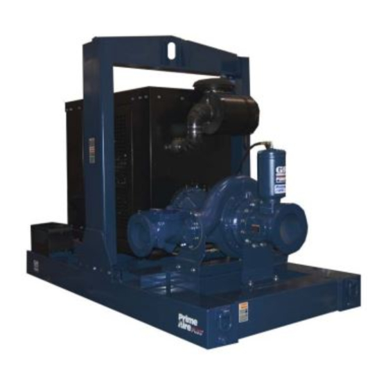
See Figure 1 for the approximate physical dimen some of the information such as mounting, line sions of this pump. OUTLINE DRAWING Figure 1. Pump Model PA8C60-6090H PREINSTALLATION INSPECTION a. Inspect the pump for cracks, dents, damaged threads, and other obvious damage. -
Page 10: Battery Installation
OM-06384 PA SERIES c. Carefully read all tags, decals, and markings pump. If chains or cable are wrapped on the pump assembly, and perform all duties around the pump to lift it, make certain indicated. Note that the pump shaft rotates in that they are positioned so as not to the required direction. -
Page 11: Suction And Discharge Piping
PA SERIES OM-06384 possible. When operation involves a suction lift, the the leveling stands are positioned on a line must always slope upward to the pump from solid surface, and the wheels are the source of the liquid being pumped; if the line chocked. -
Page 12: Suction Line Positioning
OM-06384 PA SERIES If there is a liquid flow from an open pipe into the Suction Line Positioning sump, the flow should be kept away from the suc The depth of submergence of the suction line is tion inlet because the inflow will carry air down into critical to efficient pump operation. -
Page 13: Discharge Lines
PA SERIES OM-06384 Refer to the information which follows for installa DISCHARGE LINES tion details for the liquid level sensing system pro vided with your pump. Siphoning Float Switch Installation Do not terminate the discharge line at a level lower than that of the liquid being pumped unless a si... - Page 14 OM-06384 PA SERIES ENGINE (0.9) CONTROL (.76) (Emptying) (0.6) (Filling) (.46) OPERATING (0.3) RANGE CABLE (See Table Below) TETHER (.15) POINT (Emptying) (0.3) (0.6) (0.9) (1.2) APPROXIMATE FREE CORD LENGTH IN FT. (M) 1.25” Pipe (Filling) (Not Furnished) Figure 3. Float Switch Data PAGE B - 6 INSTALLATION...
-
Page 15: Operation - Section C
OM-06384 PA SERIES OPERATION - SECTION C Review all SAFETY information in Section A. cated (see LUBRICATION in MAINTENANCE AND REPAIR). Follow the instructions on all tags, labels and The pump will begin to prime upon startup. The air decals attached to the pump. in the suction line will be discharged from the educ... -
Page 16: Automatic Starting
OM-06384 PA SERIES AL'. After the engine starts and the unit is fully Liquid Temperature And Overheating primed, adjust the engine RPM until the desired flow rate is achieved. The maximum liquid temperature for this pump is 160_ F (71_C). Do not apply it at a higher operating temperature. -
Page 17: Stopping
OM-06384 PA SERIES vacuum suction gauge readings regularly to detect normal for bearings, and they can operate safely to strainer blockage. at least 180_F (82_C). Checking bearing temperatures by hand is inaccu Never introduce air or steam pressure into the rate. -
Page 19: Troubleshooting - Section D
OM-06384 PA SERIES TROUBLESHOOTING - SECTION D Review all SAFETY information in Section A. Before attempting to open or service the pump: 1. Familiarize yourself with this manual. 2. Shut down the engine and discon nect the positive battery cable and take precautions to ensure that the pump will remain inoperative. - Page 20 OM-06384 PA SERIES TROUBLE POSSIBLE CAUSE PROBABLE REMEDY Check strainer and clean if neces Strainer clogged. PUMP STOPS OR FAILS TO DELIVER sary. RATED FLOW OR Check and clean check valve. Discharge check valve clogged. PRESSURE (cont.) Suction intake not submerged at Check installation and correct proper level or sump too small.
-
Page 21: Preventive Maintenance
OM-06384 PA SERIES TROUBLE POSSIBLE CAUSE PROBABLE REMEDY BEARINGS RUN Bearing temperature is high, but Check bearing temperature regu TOO HOT within limits. larly to monitor any increase. Low or incorrect lubricant. Check for proper type and level of lubricant. Suction and discharge lines not prop... - Page 22 OM-06384 PA SERIES Preventive Maintenance Schedule Service Interval* Item Daily Weekly Monthly Semi‐ Annually Annually General Condition (Temperature, Unusual Noises or Vibrations, Cracks, Leaks, Loose Hardware, Etc.) Pump Performance (Gauges, Speed, Flow) Bearing Lubrication Seal Lubrication (And Packing Adjustment, If So Equipped) V‐Belts (If So Equipped) Air Release Valve Plunger Rod (If So Equipped) Front Impeller Clearance (Wear Plate)
-
Page 23: Pump Maintenance And Repair - Section E
PUMP MAINTENANCE AND REPAIR - SECTION E MAINTENANCE AND REPAIR OF THE WEARING PARTS OF THE PUMP WILL MAINTAIN PEAK OPERATING PERFORMANCE. STANDARD PERFORMANCE FOR PUMP MODEL PA8C60-6090H Based on 70_F (21_C) clear water at sea level Contact the Gorman‐Rupp Company to verify per... - Page 24 OM-06384 PA SERIES PARTS PAGE SECTION DRAWING Figure 1. Pump Model PA8C60-6090H PAGE E - 2 MAINTENANCE & REPAIR...
- Page 25 OM-06384 PA SERIES PARTS LIST Pump Model PA8C60-6090H (From Canada S/N 1489510 and Up) ITEM PART MAT'L PART NAME NUMBER CODE PUMP END ASSEMBLY 46133-732 POWER UNIT KIT 46143-102 PRIMING CHAMBER KIT 48275-006 PUMP MOUNTING KIT 48157-035 PRIME AIRE DECAL...
- Page 26 OM-06384 PA SERIES SECTION DRAWING Figure 2. 46143-102 Power Unit Kit PAGE E - 4 MAINTENANCE & REPAIR...
- Page 27 OM-06384 PA SERIES PARTS LIST 46143-102 Power Unit Kit ITEM PART MAT'L PART NAME NUMBER CODE BASE/FUEL TANK 41553-016 24150 LIFTING BAIL KIT 48274-806 ENGINE (JOHN DEERE 6090H 29224-362 HEX HEAD CAPSCREW B1208 15991 HEX NUT 15991 LOCK WASHER 15991 FLAT WASHER 15991 CONTROL PANEL...
- Page 28 OM-06384 PA SERIES SECTION DRAWING Figure 3. PA8C60-(SAE 1/14) Pump End Assembly PAGE E - 6 MAINTENANCE & REPAIR...
- Page 29 OM-06384 PA SERIES PARTS LIST PA8C60-(SAE 1/14) Pump End Assembly ITEM PART MAT'L PART NAME NUMBER CODE PUMP ASSEMBLY 26837-011 SUCT SPOOL GASKET 25113-040 STUD C1414 15991 LOCK WASHER 15991 HEX NUT 15991 SUCTION SPOOL 38644-807 10000 PIPE PLUG 15079 BLIND FLANGE GASKET 25113-034 BLIND FLANGE ASSEMBLY...
- Page 30 OM-06384 PA SERIES SECTION DRAWING Figure 4. 26837-011 Pump Assembly PAGE E - 8 MAINTENANCE & REPAIR...
- Page 31 OM-06384 PA SERIES PARTS LIST 26837-011 Pump Assembly ITEM PART NAME PART MAT'L ITEM PART NAME PART MAT'L NUMBER CODE NUMBER CODE PUMP CASING 26835-253 V‐RING 26835-583 IMPELLER 26835-210 LIP SEAL 26835-806 MECHANICAL SEAL 26835-542 LIP SEAL SPRING 26835-795 PIPE PLUG 15079 MALE CONNECTOR 26351-059...
- Page 32 OM-06384 PA SERIES SECTION DRAWING Figure 5. 44162-174 Drive Assembly ITEM PART MAT'L PART NAME NUMBER CODE COUPLING KIT 48112-017 -BUSHING 24131-433 -COUPLING ASSEMBLY 24391-109 -LOCKWASHER 21171-513 -SOC HD CAPSCREW BD0812 15991 -SOC HD CAPSCREW 22644-229 HEX HD CAPSCREW B0706 15991 HEX HD CAPSCREW 22645-186...
- Page 33 OM-06384 PA SERIES SECTION DRAWING Figure 6. 48275-006 Priming Chamber Kit ITEM PART MAT'L PART NAME NUMBER CODE BALL VALVE 26631-114 STREET ELBOW RS16 11990 PRIMING CHAMBER ASSY 46112-709 HEX NUT 15991 LOCK WASHER 15991 STUD C0809 15991 BAFFLE 31113-011 17000 GASKET 38687-053...
- Page 34 OM-06384 PA SERIES SECTION DRAWING Figure 7. 46112-709 Priming Chamber Assembly ITEM PART MAT'L PART NAME NUMBER CODE PRIMING VALVE 26664-007 -ORIFICE BUTTON 26688-021 HEX HD CAPSCREW B0806 15991 LOCKWASHER 15991 STRAINER ASSY 46641-222 17000 PRIMING CHAMBER 38343-020 10000 PRIMING VALVE GASKET 38683-657 19060 INDICATES PARTS RECOMMENDED FOR STOCK...
- Page 35 PA SERIES OM-06384 PUMP AND SEAL DISASSEMBLY 4. Check the temperature before opening any covers, plates, or AND REASSEMBLY plugs. 5. Close the suction and discharge Review all SAFETY information in Section A. valves. Follow the instructions on all tags, label and de 6.
- Page 36 OM-06384 PA SERIES lift the valve components from the priming cham Pump Casing and Wear Ring Removal ber. Remove the gasket (7) and clean the mating (Figure 4) surfaces. Before attempting to remove the pump casing, re move the lowermost pipe plug (4) and drain any liq If the priming valve float is stuck or the strainer (5) is uid from the pump casing.
- Page 37 PA SERIES OM-06384 position the pump casing on the bed of an arbor (or It is recommended that the lip seal (31), spring (32) hydraulic) press with the suction opening down. and V‐ring (30) be replaced whenever the mechan Support the casing on wood blocks around the cir ical seal is replaced.
- Page 38 OM-06384 PA SERIES assembly. Disassemble the shaft and bearings Bearing Cleaning And Inspection only when there is evidence of wear or damage. Clean the frame, shaft and all component parts (ex cept the bearings) with a soft cloth soaked in clean ing solvent.
- Page 39 PA SERIES OM-06384 tion. An induction heater, hot oil bath, electric oven, ing bore, push against the outer race. Nev or hot plate may be used to heat the bearings. er hit the balls or ball cage. Bearings should never be heated with a direct Press the bearing (15) into the bearing frame until flame or directly on a hot plate.
- Page 40 OM-06384 PA SERIES ring (53) with light oil and slide the shaft sleeve onto the shaft until fully seated against the shaft shoul der. Make certain that the flexible portion of the Slide the deflectors (11) over the sleeve until coupling is mounted as shown in Figure 5.
- Page 41 PA SERIES OM-06384 during reassembly. This could result in premature age. Clean and polish the shaft sleeve, or replace it failure. If necessary to reuse an old seal in an emer if there are nicks or cuts on either end. If any com gency, carefully wash all metallic parts in fresh ponents are worn, replace the complete seal;...
- Page 42 OM-06384 PA SERIES ment, bellows and retainer) onto the sleeve until mended for maximum pump efficiency. Measure the sealing faces contact. this clearance, and add or remove impeller adjust ing shims as required. Install the seal spring and seal spacer (54). Lubri cate the seal as indicated in LUBRICATION after The pump casing must be installed in order to the impeller and remaining pump components are...
- Page 43 PA SERIES OM-06384 Apply “Loctite Threadlocker No. 242” or equivalent Install the valve cover O‐ring and secure the cover compound to the threads of the setscrews (50) and with the previously removed hardware. install the setscrews in the tapped holes in the im peller washer.
- Page 44 OM-06384 PA SERIES Bearings LUBRICATION Seal Assembly (Figure 4) (Figure 4) The bearings were fully lubricated when shipped Check the oil level regularly at the sight gauge on from the factory. Lubricate the bearings after every the seal oil reservoir and maintain it at the top of the 1,500 hours of service.
- Page 46 For U.S. and International Warranty Information, Please Visit www.grpumps.com/warranty or call: U.S.: 419-755-1280 International: +1-419-755-1011 For Canadian Warranty Information, Please Visit www.grcanada.com/warranty or call: 519-631-2870 THE GORMAN‐RUPP COMPANY D MANSFIELD, OHIO GORMAN‐RUPP OF CANADA LIMITED ST. THOMAS, ONTARIO, CANADA...
Need help?
Do you have a question about the PA8C60-6090H and is the answer not in the manual?
Questions and answers