GORMAN-RUPP PUMPS PA Series Installation, Operation, And Maintenance Manual With Parts List
Hide thumbs
Also See for PA Series:
Table of Contents

Subscribe to Our Youtube Channel
Related Manuals for GORMAN-RUPP PUMPS PA Series


Summary of Contents for GORMAN-RUPP PUMPS PA Series
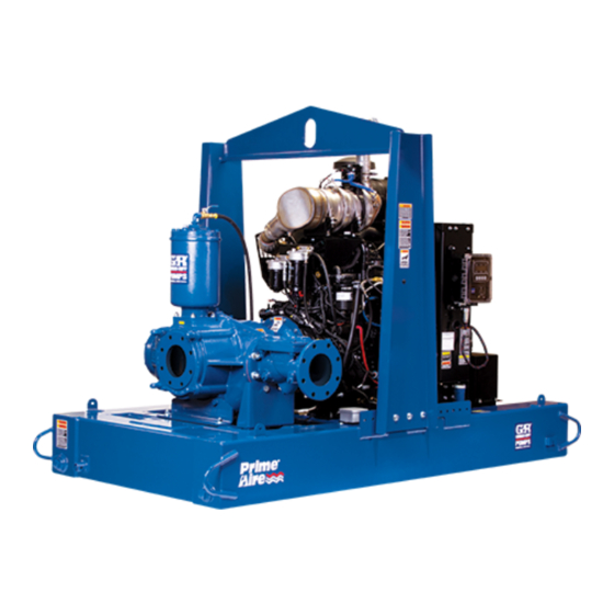
- Page 1 OM-07022-01 March 31, 2016 Rev. A 11‐17‐17 INSTALLATION, OPERATION, AND MAINTENANCE MANUAL WITH PARTS LIST PA SERIESr PUMP MODEL PA12A60-B-C6.6-ESP /S1 GORMAN‐RUPP PUMPS www.grpumps.com 2016 Gorman‐Rupp Pumps Printed in U.S.A.
- Page 2 Register your new Gorman‐Rupp pump online at www.grpumps.com Valid serial number and e‐mail address required. The engine exhaust from this product contains chemicals known to the State of California to cause cancer, birth defects or other reproductive harm. RECORD YOUR PUMP MODEL AND SERIAL NUMBER Please record your pump model and serial number in the spaces provided below.
-
Page 3: Table Of Contents
TABLE OF CONTENTS INTRODUCTION ..........PAGE I - 1 SAFETY ‐... - Page 4 TABLE OF CONTENTS (continued) PARTS LISTS: Pump Model ............PAGE E - 3 Pump Model Assembly .
-
Page 5: Introduction
PA SERIES OM-07022 INTRODUCTION Thank You for purchasing a Gorman‐Rupp pump. HAZARD AND INSTRUCTION Read this manual carefully to learn how to safely DEFINITIONS install and operate your pump. Failure to do so could result in personal injury or damage to the The following are used to alert maintenance per... -
Page 6: Safety - Section A
PA SERIES OM-07022 SAFETY ‐ SECTION A This information applies to Prime Aire the positive battery cable before per forming any maintenance. Failure to do Series pumps. Refer to the manual ac so may result in serious personal injury. companying the engine or power source before attempting to begin oper... - Page 7 OM-07022 PA SERIES components will deteriorate, and the liquid could come to a boil, build pres sure, and cause the pump casing to rup ture or explode. Momentary closure of a Make sure the pump is level. Lower jack discharge valve is acceptable only...
-
Page 8: Installation - Section B
PA SERIES OM-07022 INSTALLATION - SECTION B Review all SAFETY information in Section A. configuration, and priming must be tailored to the specific application. Since the pressure supplied Since pump installations are seldom identical, this to the pump is critical to performance and safety,... -
Page 9: Positioning Pump
OM-07022 PA SERIES c. Carefully read all tags, decals, and markings moved from the pump before lifting. Lift on the pump assembly, and perform all duties the pump or component only as high as indicated. Note that the pump shaft rotates in necessary and keep personnel away the required direction. -
Page 10: Materials
PA SERIES OM-07022 Materials the source of the liquid being pumped; if the line slopes down to the pump at any point along the Either pipe or hose maybe used for suction and suction run, air pockets will be created. -
Page 11: Suction Line Positioning
OM-07022 PA SERIES the sump, and air entering the suction line will re Suction Line Positioning duce pump efficiency. The depth of submergence of the suction line is critical to efficient pump operation. Figure 2 shows recommended minimum submergence vs. -
Page 12: Discharge Lines
PA SERIES OM-07022 Refer to the information which follows for installa DISCHARGE LINES tion details for the liquid level sensing system pro vided with your pump. Siphoning Float Switch Installation Do not terminate the discharge line at a level lower than that of the liquid being pumped unless a si... -
Page 13: Cold Weather Installation
OM-07022 PA SERIES ENGINE (0.9) CONTROL (.76) (Emptying) (0.6) (Filling) (.46) OPERATING (0.3) RANGE CABLE (See Table Below) TETHER (.15) POINT (Emptying) (0.3) (0.6) (0.9) (1.2) APPROXIMATE FREE CORD LENGTH IN FT. (M) 1.25” Pipe (Filling) (Not Furnished) Figure 3. Float Switch Data COLD WEATHER INSTALLATION from the line that runs between the top of the prim... -
Page 14: Operation - Section C
OM-07022 PA SERIES OPERATION - SECTION C OPERATION Make sure the pump is level. Lower the jack stands and chock the wheels, if so equipped. Review all SAFETY information in Section A. Follow the instructions on all tags, labels and decals attached to the pump. -
Page 15: Operation In Extreme Heat
OM-07022 PA SERIES and system operating pressure. Do not operate Leakage below the recommended operating speed (if appli cable). Once the pump is fully primed, no leakage should be visible at pump mating surfaces, or at pump connections or fittings. Keep all line connections and fittings tight to maintain maximum pump effi... -
Page 16: Strainer Check
OM-07022 PA SERIES Strainer Check Should any of the safety features cause the engine to shut down, the cause must be determined and corrected before putting the unit back into service. Check the strainer regularly, and clean it as neces... -
Page 17: Cold Weather Preservation
OM-07022 PA SERIES tenance and Repair). Bearing overheating can operated under extremely dusty conditions, also be caused by shaft misalignment and/or ex change the filter more frequently. cessive vibration. COLD WEATHER PRESERVATION When pumps are first started, the bearings may seem to run at temperatures above normal. -
Page 18: Troubleshooting - Section D
OM-07022 PA SERIES TROUBLESHOOTING - SECTION D Review all SAFETY information in Section A. Before attempting to open or service the pump: 1. Familiarize yourself with this manual. 2. Shut down the engine and discon nect the positive battery cable to en... - Page 19 OM-07022 PA SERIES TROUBLE POSSIBLE CAUSE PROBABLE REMEDY Check strainer and clean if neces Strainer clogged. PUMP STOPS OR FAILS TO DELIVER sary. RATED FLOW OR Check and clean check valve. Discharge check valve clogged. PRESSURE (cont.) Suction intake not submerged at Check installation and correct proper level or sump too small.
-
Page 20: Preventive Maintenance
OM-07022 PA SERIES TROUBLE POSSIBLE CAUSE PROBABLE REMEDY BEARINGS RUN Bearing temperature is high, but Check bearing temperature regu TOO HOT within limits. larly to monitor any increase. Low or incorrect lubricant. Check for proper type and level of lubricant. -
Page 21: Preventive Maintenance Schedule
OM-07022 PA SERIES Preventive Maintenance Schedule Service Interval* Item Daily Weekly Monthly Semi‐ Annually Annually General Condition (Temperature, Unusual Noises or Vibrations, Cracks, Leaks, Loose Hardware, Etc.) Pump Performance (Gauges, Speed, Flow) Bearing Lubrication Seal Lubrication (And Packing Adjustment, If So Equipped) V‐Belts (If So Equipped) -
Page 22: Pump Maintenance And Repair - Section E
OM-07022 PA SERIES PUMP MAINTENANCE AND REPAIR - SECTION E MAINTENANCE AND REPAIR OF THE WEARING PARTS OF THE PUMP WILL MAINTAIN PEAK OPERATING PERFORMANCE. STANDARD PERFORMANCE FOR PUMP MODEL PA12A60-B-C6.6-ESP /S1 Based on 70 F (21 C) clear water at sea level Contact the Gorman‐Rupp Company to verify per... - Page 23 OM-07022 PA SERIES ILLUSTRATION Figure 1. Pump Model PA12A60-B-C6.6-ESP /S1 PAGE E - 2 MAINTENANCE & REPAIR...
- Page 24 OM-07022 PA SERIES PARTS LIST Pump Model PA12A60-B-C6.6-ESP /S1 ITEM PART NAME PART ITEM PART NAME PART NUMBER NUMBER PUMP END ASSY 46133-538 HOSE .37 ID X 36“ LG 18513-302 CAT C6.6 ENGINE 29236-304 CHECK VALVE SUPP ASSY 41881-968 BAIL / GUARD ASSY...
- Page 25 OM-07022 PA SERIES ILLUSTRATION Figure 2. Pump Model PA12A60-B-C6.6-ESP /S1 (Cont'd) PAGE E - 4 MAINTENANCE & REPAIR...
- Page 26 OM-07022 PA SERIES PARTS LIST Pump Model PA12A60-B-C6.6-ESP /S1 (Cont'd) ITEM PART NAME PART ITEM PART NAME PART NUMBER NUMBER PUMP END ASSY 46133-538 HOSE .37 ID X 36“ LG 18513-302 CAT C6.6 ENGINE 29236-304 CHECK VALVE SUPP ASSY 41881-968...
- Page 27 OM-07022 PA SERIES ILLUSTRATION Figure 3. Pump Model PA12A60-B-C6.6-ESP /S1 (Cont'd) PAGE E - 6 MAINTENANCE & REPAIR...
- Page 28 OM-07022 PA SERIES PARTS LIST Pump Model PA12A60-B-C6.6-ESP /S1 (Cont'd) ITEM PART NAME PART ITEM PART NAME PART NUMBER NUMBER PUMP END ASSY 46133-538 HOSE .37 ID X 36“ LG 18513-302 CAT C6.6 ENGINE 29236-304 CHECK VALVE SUPP ASSY 41881-968...
- Page 29 OM-07022 PA SERIES ILLUSTRATION Figure 4. PA12A60-B /S3 Pump End Assembly PAGE E - 8 MAINTENANCE & REPAIR...
-
Page 30: Parts List
OM-07022 PA SERIES PARTS LIST PA12A60-B /S3 Pump Model Assembly (From S/N 1613950 Up) ITEM PART PART NAME NUMBER PUMP MODEL ASSY 46133-640 HEX HEAD CAP SCREW B1416 15991 LOCK WASHER J14 15991 HEX NUT D14 15991 CHECK VALVE 12"... - Page 31 OM-07022 PA SERIES ILLUSTRATION SEE FIG. 6 Figure 5. 612M60-B Pump Model Assembly PAGE E - 10 MAINTENANCE & REPAIR...
- Page 32 OM-07022 PA SERIES PARTS LIST 612M60-B Pump Model Assembly ITEM PART NAME PART ITEM PART NAME PART NUMBER NUMBER PUMP CASING SEE NOTE BELOW IMPELLER KEY N0809 15990 IMP/WEAR RING ASSY 46151-022 24110 ROLLER BEARING 23528-005 -IMPELLER NOT AVAILABLE BEARING CAP...
- Page 33 OM-07022 PA SERIES ILLUSTRATION SEE FIG. 5 Figure 6. 612M60-B Pump Model Assembly (Cont'd) PAGE E - 12 MAINTENANCE & REPAIR...
- Page 34 OM-07022 PA SERIES PARTS LIST 612M60-B Pump Model Assembly (Cont'd) ITEM PART NAME PART ITEM PART NAME PART NUMBER NUMBER PUMP CASING SEE NOTE BELOW IMPELLER KEY N0809 15990 IMP/WEAR RING ASSY 46151-022 24110 ROLLER BEARING 23528-005 -IMPELLER NOT AVAILABLE...
- Page 35 OM-07022 PA SERIES ILLUSTRATION Figure 7. 48275-014 Heated Priming Chamber Kit ITEM PART PART NAME NUMBER HEATED PRIMING CHAMBER ASSEMBLY 46112-713 HEATED COVER PLATE ASSY 31113-011 17000 STREET ELBOW RS16 11999 BALL VALVE 26631-054 STREET ELBOW RS08 11999 PIPE PLUG...
- Page 36 OM-07022 PA SERIES ILLUSTRATION Figure 8. 46112-713 Heated Priming Chamber Assembly PARTS LIST ITEM PART PART NAME NUMBER PRIMING VALVE 26664-007 -ORIFICE BUTTON 26688-021 HEX HEAD CAP SCREW B0806 15991 LOCK WASHER J08 15991 PRIMING VALVE GASKET 38683-657 19060 PRIMING CHAMBER...
- Page 37 OM-07022 PA SERIES ILLUSTRATION Figure 9. 44162-179 Engine Drive Assembly ITEM PART PART NAME NUMBER RETAINING RING 24121-075 RETAINING RING S215 BALL BEARING 23282-012 OUTPUT SHAFT 38512-051 N0612 15990 BEARING HOUSING 38251-001 11010 SOCKET HEAD CAPSCREW BD0606-1/2S 15991 LOCK WASHER...
- Page 38 OM-07022 PA SERIES ILLUSTRATION IMPELLER WEAR RING NOTE: UNLESS OTHERWISE SPECIFIED, MACHINED SURFACES TO BE 125 RMS. Figure 10. Impeller Assembly Machining Tolerances MAINTENANCE & REPAIR PAGE E - 17...
-
Page 39: Pump And Seal Disassembly And Reassembly
OM-07022 PA SERIES PUMP AND SEAL DISASSEMBLY pump integrity are compromised by such practices. AND REASSEMBLY Review all SAFETY information in Section A. Follow the instructions on all tags, label and de Before attempting to open or service the cals attached to the pump. - Page 40 PA SERIES OM-07022 The flapper and cover gasket are the only service the pump or component only as high as able parts of the check valve. If the flapper requires necessary and keep personnel away replacement, remove the hardware securing the from suspended objects.
- Page 41 OM-07022 PA SERIES the oiler during disassembly. bearing failure, or other damage to the pump. If the impeller (2) is to be removed, the impeller To replace the wear ring, grind off the three weld screw (7) should be loosened before removing the spots securing the wear ring to the impeller.
- Page 42 PA SERIES OM-07022 horizontally to provide clearance for removal of the the bearing cap gasket (29) and clean the mating the pump drive belt (101) from the sprocket (99). surfaces. Press the oil seal from the bearing cap. Place a block of wood against the impeller end of...
- Page 43 OM-07022 PA SERIES sembly. Disassemble the shaft and bearings only when there is evidence of wear or damage. Most cleaning solvents are toxic and flammable. Use them only in a well ven tilated area free from excessive heat, Shaft and bearing disassembly in the field sparks, and flame.
- Page 44 PA SERIES OM-07022 The bearings may be heated to ease installation. Install the key (5) in the output shaft keyway. Posi An induction heater, hot oil bath, electric oven, or tion the flexible portion of the coupling assembly hot plate may be used to heat the bearings. Bear...
- Page 45 OM-07022 PA SERIES 242' or equivalent compound to the threads of the hardware (7and 9), and secure the outer ring of the coupling to the engine flywheel by torquing the hardware to 45 ft. lbs. (540 in. lbs. or 6,2 m. kg.).
- Page 46 PA SERIES OM-07022 sleeve and a press to reposition the bearings Slide the sprocket over the hub, align the mounting against the shaft shoulder. screw holes and install the mounting screws. Position the hub and sprocket to the dimensions Secure the assembled shaft and bearings by shown in Figure 11 and torque the mounting caps...
- Page 47 OM-07022 PA SERIES zontally and tighten the belt tension to 3/8 inch (9,5 seal plate cover with the lip positioned as shown in mm) of deflection at 30 lbs. (13,6 kg.) of pressure. Detail E, Figure 6. Do not over‐tighten the drive belt.
- Page 48 PA SERIES OM-07022 SPRING RETAINER SEAL PLATE IMPELLER SHAFT STATIONARY SLEEVE ELEMENT O‐RING IMPELLER ROTATING SHAFT ELEMENT O‐RINGS BELLOWS SHAFT SLEEVE STATIONARY SEAT IMPELLER SHIMS Figure 12. Seal Assembly the pedestal with three 1/2‐inch by 2‐inch long capscrews and nuts (not supplied).
- Page 49 OM-07022 PA SERIES Impeller Installation A clearance of approximately .025 to .040 inch (0,63 to 1,04 mm) between the impeller and the (Figure 5) seal plate is recommended for maximum pump ef ficiency. Measure this clearance, and add or re...
- Page 50 PA SERIES OM-07022 Install the suction head gasket (52). Position the Install the strainer (6) and priming valve gasket (4). suction head over the studs (53) and secure it with Lower the float into the priming chamber (5) and the hardware (14 and 15).
- Page 51 OM-07022 PA SERIES Engine ture condensation. This is especially im portant in areas where variable hot and Consult the literature supplied with the engine, or cold temperatures are common. contact your local engine representative. For cold weather operation, consult the factory or a lubricant supplier for the recommended grade of oil.
- Page 52 For Warranty Information, Please Visit www.grpumps.com/warranty or call: U.S.: 419-755-1280 Canada: 519-631-2870 International: +1-419-755-1352 GORMAN‐RUPP PUMPS...
Need help?
Do you have a question about the PA Series and is the answer not in the manual?
Questions and answers