GORMAN-RUPP PUMPS PA Series Installation, Operation, And Maintenance Manual With Parts List
Hide thumbs
Also See for PA Series:
Table of Contents
Advertisement
Quick Links
ACDEU
OM‐05768‐01
August 30, 2005
Rev. C 01‐13‐16
INSTALLATION, OPERATION,
AND MAINTENANCE MANUAL
WITH PARTS LIST
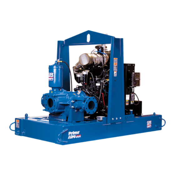
PA SERIES PUMP
MODEL
PA6C60C-F4L
THE GORMAN‐RUPP COMPANY D MANSFIELD, OHIO
D
GORMAN‐RUPP OF CANADA LIMITED
ST. THOMAS, ONTARIO, CANADA
Printed in U.S.A
www.gormanrupp.com.
E
Copyright by the Gorman‐Rupp Company
Advertisement
Table of Contents

Subscribe to Our Youtube Channel
Related Manuals for GORMAN-RUPP PUMPS PA Series


Summary of Contents for GORMAN-RUPP PUMPS PA Series
- Page 1 ACDEU OM‐05768‐01 August 30, 2005 Rev. C 01‐13‐16 INSTALLATION, OPERATION, AND MAINTENANCE MANUAL WITH PARTS LIST PA SERIES PUMP MODEL PA6C60C-F4L THE GORMAN‐RUPP COMPANY D MANSFIELD, OHIO GORMAN‐RUPP OF CANADA LIMITED ST. THOMAS, ONTARIO, CANADA Printed in U.S.A www.gormanrupp.com. Copyright by the Gorman‐Rupp Company...
- Page 2 Register your new Gorman‐Rupp pump online at www.grpumps.com Valid serial number and e‐mail address required. The engine exhaust from this product contains chemicals known to the State of California to cause cancer, birth defects or other reproductive harm. RECORD YOUR PUMP MODEL AND SERIAL NUMBER Please record your pump model and serial number in the spaces provided below.
-
Page 3: Table Of Contents
TABLE OF CONTENTS INTRODUCTION ..........PAGE I - 1 SAFETY ‐... - Page 4 TABLE OF CONTENTS (continued) Manual Stopping ............PAGE C - 4 Automatic Stopping .
-
Page 5: Introduction
This pump is a PA Series, priming‐assisted centrif ugal model. The unit is designed for handling non‐ volatile, non‐flammable liquids containing speci fied entrained solids. The basic material of con... -
Page 6: Safety - Section A
PA SERIES OM-05768 SAFETY ‐ SECTION A This information applies to Prime Aire forming any maintenance. Failure to do Series pumps. Refer to the manual ac so may result in serious personal injury. companying the engine or power source before attempting to begin oper... - Page 7 OM-05768 PA SERIES Pumps and related equipment must be in Do not operate the pump against a stalled and operated according to all na closed discharge valve. If operated tional, local and industry standards. against a closed discharge valve, pump components will deteriorate, and the liquid could come to a boil, build pres...
-
Page 8: Installation - Section B
PA SERIES OM-05768 INSTALLATION - SECTION B Review all SAFETY information in Section A. configuration, and priming must be tailored to the specific application. Since the pressure supplied to the pump is critical to performance and safety, Since pump installations are seldom identical, this... -
Page 9: Preinstallation Inspection
OM-05768 PA SERIES Battery Installation PREINSTALLATION INSPECTION Unless otherwise specified on the pump order, the The pump assembly was inspected and tested be engine battery is not included with engine driven fore shipment from the factory. Before installation, units. inspect the pump for damage which may have oc... -
Page 10: Mounting
PA SERIES OM-05768 used in suction lines, it must be the rigid‐wall, rein forced type to prevent collapse under suction. Us ing piping couplings in suction lines is not recom mended. The pump assembly can be seriously damaged if the chains or cables used to lift... -
Page 11: Strainers
OM-05768 PA SERIES should be the eccentric type, and should be in If there is a liquid flow from an open pipe into the stalled with the flat part of the reducers uppermost sump, the flow should be kept away from the suc... -
Page 12: Discharge Lines
PA SERIES OM-05768 Figure 2. Recommended Minimum Suction Line Submergence vs. Velocity DISCHARGE LINES Siphoning If the application involves a high discharge head, gradually close the discharge Do not terminate the discharge line at a level lower than that of the liquid being pumped unless a si... -
Page 13: Float Switch Installation
OM-05768 PA SERIES Float Switch Installation pipe is available, attach the float switch cable to the standpipe in the sump at the approxi The Float Switch autostart system employs either a mate desired liquid level. single or double float switch, where a bulb raises or lowers (floats) with the liquid level, thus activating b. -
Page 14: Operation - Section C
OM-05768 PA SERIES OPERATION - SECTION C Review all SAFETY information in Section A. cated (see LUBRICATION in MAINTENANCE AND REPAIR). Follow the instructions on all tags, labels and The pump will begin to prime upon startup. The air decals attached to the pump. -
Page 15: Automatic Starting
OM-05768 PA SERIES box to the “START” position until the engine starts. and the alarm will sound for approximately 8 sec Release the key and the switch will return to the onds before the unit starts. “RUN” position. When the liquid level in the sump or wet well is suffi... -
Page 16: Routine Operation
OM-05768 PA SERIES Routine Operation This pump is equipped with automatic liquid level controls, and is subject to automatic restart. Keep hands and Do not operate an internal combustion clothing away from the unit to prevent engine in an explosive atmosphere. -
Page 17: Strainer Check
OM-05768 PA SERIES After stopping the pump, switch off the engine igni pletely cool before servicing. Do not re tion and remove the key to ensure that the pump move plates, covers, gauges, or fittings will remain inoperative. from an overheated pump. Liquid within the pump can reach boiling tempera... - Page 18 OM-05768 PA SERIES conditions, change the filter more frequently. Irreg ty shutdown features are pre‐set at the ular performance and loss of power usually indi factory; do not attempt to adjust any of cate a dirty fuel filter. the settings. Determine the cause of shutdown before putting the unit back into service.
- Page 19 OM-05768 PA SERIES TROUBLESHOOTING - SECTION D Review all SAFETY information in Section A. 5. Close the suction and discharge valves. 6. Vent the pump slowly and cau tiously. 7. Drain the pump. Before attempting to open or service the pump: 1.
- Page 20 OM-05768 PA SERIES TROUBLE POSSIBLE CAUSE PROBABLE REMEDY Check strainer and clean if neces Strainer clogged. PUMP STOPS OR FAILS TO DELIVER sary. RATED FLOW OR Check and clean check valve. Discharge check valve clogged. PRESSURE (cont.) Suction intake not submerged at Check installation and correct proper level or sump too small.
- Page 21 OM-05768 PA SERIES TROUBLE POSSIBLE CAUSE PROBABLE REMEDY BEARINGS RUN Bearing temperature is high, but Check bearing temperature regu TOO HOT within limits. larly to monitor any increase. Low or incorrect lubricant. Check for proper type and level of lubricant.
- Page 22 OM-05768 PA SERIES Preventive Maintenance Schedule Service Interval* Item Daily Weekly Monthly Semi‐ Annually Annually General Condition (Temperature, Unusual Noises or Vibrations, Cracks, Leaks, Loose Hardware, Etc.) Pump Performance (Gauges, Speed, Flow) Bearing Lubrication Seal Lubrication (And Packing Adjustment, If So Equipped) V‐Belts (If So Equipped)
- Page 23 OM-05768 PA SERIES PUMP MAINTENANCE AND REPAIR - SECTION E MAINTENANCE AND REPAIR OF THE WEARING PARTS OF THE PUMP WILL MAINTAIN PEAK OPERATING PERFORMANCE. STANDARD PERFORMANCE FOR PUMP MODEL PA6C60C-F4L Based on 70_F (21_C) clear water at sea level Contact the Gorman‐Rupp Company to verify per...
- Page 24 OM-05768 PA SERIES PARTS PAGE SECTION DRAWING Figure 1. Pump Model PA6C60C-F4L PAGE E - 2 MAINTENANCE & REPAIR...
- Page 25 OM-05768 PA SERIES Pump Model PA6C60C-F4L PARTS LIST (From S/N 1318119 up) ITEM PART MAT'L PART NAME NUMBER CODE PUMP END PA6C60C-(SAE 4/10) --- POWER UNIT KIT 46143-035 BATTERY SEE OPTIONS PUMP MOUNTING KIT 48157-023 NOT SHOWN: G‐R DECAL GR-06...
- Page 26 OM-05768 PA SERIES SECTION DRAWING Figure 2. 46143-035 Power Unit Kit PAGE E - 4 MAINTENANCE & REPAIR...
- Page 27 OM-05768 PA SERIES PARTS LIST 46143-035 Power Unit Kit ITEM PART MAT'L PART NAME NUMBER CODE DEUTZ F4L ENGINE 29217-243 BASE/FUEL TANK 41553-006 24150 MUFFLER GUARD 32331-031 NEG. BATTERY CABLE 47311-184 POS. BATTERY CABLE 47311-143 BATTERY BOX ASSY 42432-005 OIL DRAIN ASSY...
- Page 28 OM-05768 PA SERIES Figure 3. PA6C60C-(SAE 4/10) Pump Assembly PAGE E - 6 MAINTENANCE & REPAIR...
- Page 29 OM-05768 PA SERIES PA6C60C-(SAE 4/10) Pump Assembly PARTS LIST ITEM PART MAT'L PART NAME NUMBER CODE PUMP END 66F60C-(SAE 4/10) --- PRIMING CHAMBER KIT 48275-005 HOSE BARB FITTING 26523-047 1/2 IN. CONNECTOR S1598 1/2 IN. I.D. X 30 IN. LG. HOSE...
- Page 30 OM-05768 PA SERIES SECTION DRAWING Figure 4. 66F60C-(SAE 4/10) Pump End Assembly PAGE E - 8 MAINTENANCE & REPAIR...
- Page 31 OM-05768 PA SERIES PARTS LIST 64C60C-(SAE 4/10) Pump End Assembly ITEM PART MAT'L PART NAME NUMBER CODE PUMP CASING 38218-303 11010 REPAIR ROTATING ASSY 44163-445 HEX HD CAPSCREW B0604-1/2 17000 LOCK WASHER 17090 WEAR PLATE 38691-864 11010 O‐RING 25152-453 PIPE PLUG...
- Page 32 OM-05768 PA SERIES SECTION DRAWING DRIVE END VIEW Figure 5. 44163-445 Repair Rotating Assembly PAGE E - 10 MAINTENANCE & REPAIR...
- Page 33 OM-05768 PA SERIES PARTS LIST 44163-445 Repair Rotating Assembly ITEM PART MAT'L PART NAME NUMBER CODE IMPELLER 38615-092 11010 SEAL ASSEMBLY 46512-149 BALL BEARING 23422-019 BEARING HOUSING 38251-513 10000 VENTED PLUG 4823A 15079 AIR VENT S1530 RED PIPE BUSHING AP0802...
- Page 34 OM-05768 PA SERIES SECTION DRAWING Figure 6. 48275-005 Priming Chamber Kit ITEM PART MAT'L PART NAME NUMBER CODE PRIMING CHAMBER ASSY 46112-709 PIPE BUSHING AP1608 11999 STREET ELBOW RS08 11999 BALL VALVE 26631-052 STUD C0809 15991 HEX NUT 15991 LOCK WASHER...
- Page 35 OM-05768 PA SERIES SECTION DRAWING Figure 7. 46112-709 Priming Chamber Assembly PARTS LIST ITEM PART MAT'L PART NAME NUMBER CODE PRIMING VALVE 26664-007 -ORIFICE BUTTON 26688-021 HEX HD CAPSCREW B0806 15991 LOCKWASHER 15991 STRAINER ASSY 46641-222 17000 PRIMING CHAMBER 38343-020...
- Page 36 OM-05768 PA SERIES SECTION DRAWING Figure 8. 44162-159 Drive Assembly ITEM PART MAT'L PART NAME NUMBER CODE COUPLING ASSY 44165-016 BUSHING 24131-498 -KEY 24113-603 DRIVE FLANGE 38545-004 IMPELLER SHAFT 38515-586 1706H LOCK WASHER 21171-536 SOCKET HEAD CAPSCREW 22644-220 HEX HD CAPSCREW...
- Page 37 OM-05768 PA SERIES PUMP AND SEAL DISASSEMBLY any procedures not addressed in this manual are performed only after estab AND REASSEMBLY lishing that neither personal safety nor Review all SAFETY information in Section A. pump integrity are compromised by Follow the instructions on all tags, label and de...
- Page 38 OM-05768 PA SERIES Discharge Check Valve Removal and Disassembly (Figure 3) Use only replacement parts provided or Remove the hardware (not shown) securing the approved by Gorman‐Rupp. Use of non‐ discharge check valve bracket to the base. authorized parts may result in damage to...
- Page 39 OM-05768 PA SERIES Disengage the hardware (11 and 12) and remove install the capscrews in the tapped holes in the the belt guard assembly (7). Remove the hardware bushing and tighten them in an alternating pattern (8, 9 and 10) securing the air compressor assem...
- Page 40 OM-05768 PA SERIES move the shims (14) and clean the contacting sur Turn faces. Tie and tag the shims or measure and re Counterclockwise cord their thickness for ease of reassembly. Impeller Removal (Figure 5) Lathe Dog Arm With the rotating assembly removed from the pump casing, unscrew the impeller (1) in a coun...
- Page 41 OM-05768 PA SERIES Shaft and Bearing Removal and Disassembly (Figure 5) Most cleaning solvents are toxic and When the pump is properly operated and main flammable. Use them only in a well ven tained, the bearing housing should not require dis...
- Page 42 OM-05768 PA SERIES If heating the bearings is not practical, use a suit ably sized sleeve and an arbor (or hydraulic) press to install the bearings on the shaft. To prevent damage during removal from the shaft, it is recommended that bearings be cleaned and inspected in place.
- Page 43 OM-05768 PA SERIES Securing Bearing Housing And Drive Assembly pre‐load condition can cause premature To Engine bearing failure. The coupling must be positioned 1.44 (Figure 4) inch (37 mm) from the end of the shaft. Install the key (34 Figure 5) in the shaft keyway, This will allow the two portions of the cou...
- Page 44 OM-05768 PA SERIES Seal Reassembly and Installation Reusing an old seal could result in prema ture failure. (Figures 5, 10, 11 and 12) The seal is not normally reused because wear pat terns on the finished faces cannot be realigned during reassembly.
- Page 45 OM-05768 PA SERIES SPRING RETAINER SPRING O‐RING CENTERING WASHER STATIONARY IMPELLER SEAT SHIMS SHAFT SLEEVE O‐RING IMPELLER SHAFT SHAFT SLEEVE IMPELLER ROTATING ELEMENT SEAL PLATE BELLOWS Figure 10. 46513-149 Seal Assembly the tubing wall should be as thin as possible. The length should be long enough to cover the threads on the end of the shaft.
- Page 46 OM-05768 PA SERIES Impeller Installation And Adjustment sembly to the pump casing with the hardware (12 and 13). (Figure 5) Wear Plate And Back Cover Plate Installation Inspect the impeller (1) and replace it if cracked or And Adjustment badly worn.
- Page 47 OM-05768 PA SERIES Align the back cover plate over the studs (21) and Discharge Check Valve Reassembly And slide it into the pump casing. Use two hand knobs Installation (22) on diagonally opposing studs to press the (Figure 3) back cover into the pump casing until the wear If the discharge check valve (26) was disas...
- Page 48 OM-05768 PA SERIES chamber assembly on the hopper spool (31, Fig Clean and reinstall the air vent. Do not over‐lubri ure 3). Secure the priming chamber assembly with cate. Over‐lubrication can cause the bearings to the hardware (6 and 7).
- Page 49 For U.S. and International Warranty Information, Please Visit www.grpumps.com/warranty or call: U.S.: 419-755-1280 International: +1-419-755-1352 For Canadian Warranty Information, Please Visit www.grcanada.com/warranty or call: 519-631-2870 THE GORMAN‐RUPP COMPANY D MANSFIELD, OHIO GORMAN‐RUPP OF CANADA LIMITED ST. THOMAS, ONTARIO, CANADA...
Need help?
Do you have a question about the PA Series and is the answer not in the manual?
Questions and answers