GORMAN-RUPP PUMPS PA Series Installation, Operation, And Maintenance Manual With Parts List
Hide thumbs
Also See for PA Series:

Related Manuals for GORMAN-RUPP PUMPS PA Series


Summary of Contents for GORMAN-RUPP PUMPS PA Series
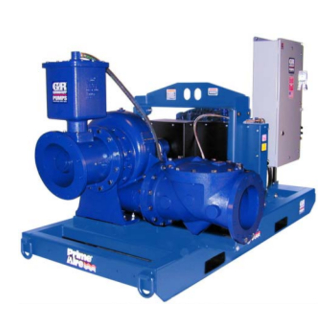
- Page 1 OM-05770-02 May 11, 2011 Rev. A - 7/23/19 INSTALLATION, OPERATION, AND MAINTENANCE MANUAL WITH PARTS LIST PA SERIES PUMP MODEL PA6C60C-F5L GORMAN‐RUPP PUMPS www.grpumps.com 2011 Gorman‐Rupp Pumps Printed in U.S.A.
- Page 2 Register your new Gorman‐Rupp pump online at www.grpumps.com Valid serial number and e‐mail address required. The engine exhaust from this product contains chemicals known to the State of California to cause cancer, birth defects or other reproductive harm. RECORD YOUR PUMP MODEL AND SERIAL NUMBER Please record your pump model and serial number in the spaces provided below.
-
Page 3: Table Of Contents
TABLE OF CONTENTS INTRODUCTION ..........PAGE I - 1 SAFETY ‐... - Page 4 TABLE OF CONTENTS (continued) PERIODIC CHECKS ............PAGE C - 5 Seal Cavity and Bearing Lubrication .
-
Page 5: Introduction
This pump is a PA Series, priming‐assisted centrif ugal model. The unit is designed for handling non‐ volatile, non‐flammable liquids containing speci fied entrained solids. The basic material of con... -
Page 6: Safety - Section A
PA SERIES OM-05770 SAFETY ‐ SECTION A This information applies to Prime Aire forming any maintenance. Failure to do Series pumps. Refer to the manual ac so may result in serious personal injury. companying the engine or power source before attempting to begin oper... - Page 7 OM-05770 PA SERIES hose connections are tight, properly supported and secure before operation. Pumps and related equipment must be in stalled and operated according to all na tional, local and industry standards. Do not operate the pump against a closed discharge valve.
-
Page 8: Installation - Section B
PA SERIES OM-05770 INSTALLATION - SECTION B Review all SAFETY information in Section A. configuration, and priming must be tailored to the specific application. Since the pressure supplied to the pump is critical to performance and safety, Since pump installations are seldom identical, this... -
Page 9: Preinstallation Inspection
OM-05770 PA SERIES Battery Installation PREINSTALLATION INSPECTION Unless otherwise specified on the pump order, the The pump assembly was inspected and tested be engine battery was not included with the unit. fore shipment from the factory. Before installation, When selecting a battery, refer to the specifications inspect the pump for damage which may have oc... -
Page 10: Mounting
PA SERIES OM-05770 used in suction lines, it must be the rigid‐wall, rein forced type to prevent collapse under suction. Us ing piping couplings in suction lines is not recom mended. The pump assembly can be seriously damaged if the chains or cables used to lift... -
Page 11: Strainers
OM-05770 PA SERIES should be the eccentric type, and should be in If there is a liquid flow from an open pipe into the stalled with the flat part of the reducers uppermost sump, the flow should be kept away from the suc... -
Page 12: Discharge Lines
PA SERIES OM-05770 Figure 2. Recommended Minimum Suction Line Submergence vs. Velocity DISCHARGE LINES Siphoning If the application involves a high discharge head, gradually close the discharge Do not terminate the discharge line at a level lower than that of the liquid being pumped unless a si... -
Page 13: Float Switch Installation
OM-05770 PA SERIES Float Switch Installation pipe is available, attach the float switch cable to the standpipe in the sump at the approxi The Float Switch autostart system employs either a mate desired liquid level. single or double float switch, where a bulb raises or lowers (floats) with the liquid level, thus activating b. -
Page 14: Operation - Section C
OM-05770 PA SERIES OPERATION - SECTION C Review all SAFETY information in Section A. cated (see LUBRICATION in MAINTENANCE AND REPAIR). Follow the instructions on all tags, labels and The pump will begin to prime upon startup. The air decals attached to the pump. -
Page 15: Automatic Starting
OM-05770 PA SERIES box to the “START” position until the engine starts. and the alarm will sound for approximately 8 sec Release the key and the switch will return to the onds before the unit starts. “RUN” position. When the liquid level in the sump or wet well is suffi... -
Page 16: Routine Operation
OM-05770 PA SERIES Routine Operation OPERATIONAL CHECKS Leakage Once the pump is fully primed, no leakage should be visible at pump mating surfaces, or at pump connections or fittings. Keep all line connections Do not operate an internal combustion and fittings tight to maintain maximum pump effi... -
Page 17: Strainer Check
OM-05770 PA SERIES Strainer Check automatically when the liquid rises and activates the “On” float switch(s). Check the strainer regularly, and clean it as neces sary. The strainer should also be checked if pump Safety Shutdown System flow rate begins to drop. Monitor and record the vacuum suction gauge readings regularly to detect The unit is equipped with a safety system to auto... - Page 18 OM-05770 PA SERIES If operated under extremely dusty and/or humid PERIODIC CHECKS conditions, change the filter more frequently. Irreg ular performance and loss of power usually indi Seal Cavity And Bearing Lubrication cate a dirty fuel filter. Both the seal and bearing cavities were fully lubri...
- Page 19 OM-05770 PA SERIES TROUBLESHOOTING - SECTION D Review all SAFETY information in Section A. 5. Close the suction and discharge valves. 6. Vent the pump slowly and cau tiously. 7. Drain the pump. Before attempting to open or service the pump: 1.
- Page 20 OM-05770 PA SERIES TROUBLE POSSIBLE CAUSE PROBABLE REMEDY Check strainer and clean if neces Strainer clogged. PUMP STOPS OR FAILS TO DELIVER sary. RATED FLOW OR Check and clean check valve. Discharge check valve clogged. PRESSURE (cont.) Suction intake not submerged at Check installation and correct proper level or sump too small.
- Page 21 OM-05770 PA SERIES TROUBLE POSSIBLE CAUSE PROBABLE REMEDY BEARINGS RUN Bearing temperature is high, but Check bearing temperature regu TOO HOT within limits. larly to monitor any increase. Low or incorrect lubricant. Check for proper type and level of lubricant.
- Page 22 OM-05770 PA SERIES Preventive Maintenance Schedule Service Interval* Item Daily Weekly Monthly Semi‐ Annually Annually General Condition (Temperature, Unusual Noises or Vibrations, Cracks, Leaks, Loose Hardware, Etc.) Pump Performance (Gauges, Speed, Flow) Bearing Lubrication Seal Lubrication (And Packing Adjustment, If So Equipped) V‐Belts (If So Equipped)
- Page 23 OM-05770 PA SERIES PUMP MAINTENANCE AND REPAIR - SECTION E MAINTENANCE AND REPAIR OF THE WEARING PARTS OF THE PUMP WILL MAINTAIN PEAK OPERATING PERFORMANCE. STANDARD PERFORMANCE FOR PUMP MODEL PA6C60C-F5L Based on 70 F (21 C) clear water at sea level Contact the Gorman‐Rupp Company to verify per...
- Page 24 OM-05770 PA SERIES PARTS PAGE ILLUSTRATION + − Figure 1. Pump Model PA6C60C-F5L PAGE E - 2 MAINTENANCE & REPAIR...
- Page 25 OM-05770 PA SERIES Pump Model PA6C60C-F5L PARTS LIST (From S/N 1542350 Up) ITEM PART PART NAME NUMBER PUMP END ASSEMBLY PA6C60C-(SAE 4/10) POWER UNIT KIT 46143-052 BATTERY SEE OPTIONS PUMP MOUNTING KIT 48157-023 NOT SHOWN: G‐R DECAL GR-06 PRIME AIRE DECAL...
- Page 26 OM-05770 PA SERIES ILLUSTRATION DETAIL A Figure 2. Power Unit Kit PAGE E - 4 MAINTENANCE & REPAIR...
- Page 27 OM-05770 PA SERIES PARTS LIST Power Unit Kit ITEM PART PART NAME NUMBER BASE/FUEL TANK 41553-031 24150 ENGINE RAIL 34451-086 15080 ENGINE RAIL 34451-085 15080 EXHAUST ELBOW 31912-024 15990 WEATHER CAP S1246 LIFTING BAIL KIT 48274-801 MUFFLER GUARD ASSEMBLY 42331-033...
- Page 28 OM-05770 PA SERIES ILLUSTRATION Figure 3. Pump Assembly PAGE E - 6 MAINTENANCE & REPAIR...
- Page 29 OM-05770 PA SERIES Pump Assembly PARTS LIST ITEM PART PART NAME NUMBER PUMP END ASSEMBLY 46133-687 PRIMING CHAMBER KIT 48275-005 HOSE BARB FITTING 26523-047 CONNECTOR 1/2 S1598 1/2 X 30" LG HOSE 18513-113 AIR COMPRESSOR ASSY 46181-906 BELT GUARD ASSY...
- Page 30 OM-05770 PA SERIES ILLUSTRATION Figure 4. Pump End Assembly PAGE E - 8 MAINTENANCE & REPAIR...
- Page 31 OM-05770 PA SERIES PARTS LIST Pump End Assembly ITEM PART PART NAME NUMBER PUMP CASING SEE NOTE BELOW REPAIR ROTATING ASSEMBLY 44163-445 HEX HEAD CAP SCREW B0604-1/2 17000 LOCK WASHER J06 17090 WEAR PLATE 38691-864 11010 WEAR PLATE O‐RING 25152-453...
- Page 32 OM-05770 PA SERIES ILLUSTRATION Ç Ç Ç Ç Ç Î Î Î Î Î Ç Ç Ç Ç Ç Ç Ç Ç Î Î Î Î Î Ï Ï Ì Ì Ï Ç Ç Ï Ï Ì Ì Ì Î Î Î Î...
- Page 33 OM-05770 PA SERIES PARTS LIST Repair Rotating Assembly ITEM PART PART NAME NUMBER IMPELLER - HIGH HEAD 38615-092 11010 SEAL ASSEMBLY 46512-149 BALL BEARING 23422-019 BEARING HOUSING 38251-513 10000 VENTED PIPE PLUG 4823A 15079 AIR VENT S1530 REDUCER PIPE BUSHING...
- Page 34 OM-05770 PA SERIES ILLUSTRATION Figure 6. Priming Chamber Kit PARTS LIST ITEM PART PART NAME NUMBER PRIMING CHAMBER ASSEMBLY 46112-709 REDUCER PIPE BUSHING AP1608 15070 STREET ELBOW RS08 11999 BALL VALVE 1/2" 26631-052 STUD C0809 15991 HEX NUT D08 15991...
- Page 35 OM-05770 PA SERIES ILLUSTRATION Figure 7. Priming Chamber Assembly PARTS LIST ITEM PART PART NAME NUMBER PRIMING VALVE 26664-007 -ORIFICE BUTTON 26688-021 HEX HD CAPSCREW B0806 15991 LOCKWASHER J08 15991 PRIMING VALVE GASKET 38683-657 19060 PRIMING CHAMBER 38343-020 10000 STRAINER ASSY...
- Page 36 OM-05770 PA SERIES ILLUSTRATION Ì Ì Ì Ì Ì Ç Ç Ç Ç Ì Ì Ì Ì Ì Ç Ç Ç Ç Ï Ï Ï Ï Ï Ï Ï Ì Ì Ì Ì Ì Ç Ç Ç Ç Ç Ç Ç...
- Page 37 OM-05770 PA SERIES ILLUSTRATION VENTURI DETAIL Figure 9. Air Compressor Assembly PARTS LIST ITEM PART PART NAME NUMBER MACH SCREW X#10-02 15991 HEX NUT D#10 15991 LOCK WASHER J#10 15991 FLAT WASHER K#10 15991 AIR COMPRESSOR COVER 38354-043 15120 AIR COMPRESSOR...
- Page 38 OM-05770 PA SERIES PUMP AND SEAL DISASSEMBLY lishing that neither personal safety nor pump integrity are compromised by AND REASSEMBLY such practices. Review all SAFETY information in Section A. Follow the instructions on all tags, label and de cals attached to the pump.
- Page 39 OM-05770 PA SERIES The only serviceable part of the priming valve is the tomatic starting system, and therefore orifice button (not shown). If liquid continues to by subject to automatic restart. Keep pass through the priming chamber after adjusting hands and clothing away from the unit to the orifice button (see Priming Chamber Reas...
- Page 40 OM-05770 PA SERIES back cover out of the pump casing. pling must be replaced. To remove the ring, disen gage the hardware (5 and 6) securing it to the fly wheel. Remove and discard the O‐rings (6 and16). Remove any leveling shims used under the casing Inspect the wear plate and, if replacement is re...
- Page 41 OM-05770 PA SERIES against the arm of the lathe dog in a counterclock Impeller Removal wise direction (when facing the drive end of the (Figure 5) shaft). Use caution not to damage the shaft or key way. When the impeller breaks loose, remove the With the rotating assembly removed from the lathe dog, key and wood block.
- Page 42 OM-05770 PA SERIES assembly. Disassemble the shaft and bearings tilated area free from excessive heat, only when there is evidence of wear or damage. sparks, and flame. Read and follow all precautions printed on solvent contain ers. Clean the bearings thoroughly in fresh cleaning solvent.
- Page 43 OM-05770 PA SERIES be replaced any time the shaft and bear race, balls, or ball cage. Press only on the ings are removed. inner race. Install the thrust washer (13) and secure the out NOTE board bearing (8) to the shaft with the snap ring The inboard bearing (3) comes from the manufac...
- Page 44 OM-05770 PA SERIES drive key (31, Figure 5). Install the bushing (10) and pling until the tapped holes for the two setscrews sprocket (11) on the shaft to the dimension shown align with those in the bushing, and install the set...
- Page 45 OM-05770 PA SERIES ing with the previously removed hardware (7 and (Figure 3) A new seal assembly should be installed any time the old seal is removed from the Use a suitable hoist and sling to position the air pump. Wear patterns on the finished faces compressor assembly (6) on the mounting flange cannot be realigned during reassembly.
- Page 46 OM-05770 PA SERIES SPRING RETAINER SPRING O‐RING CENTERING WASHER STATIONARY IMPELLER SEAT SHIMS SHAFT SLEEVE O‐RING IMPELLER SHAFT SHAFT SLEEVE IMPELLER ROTATING ELEMENT SEAL PLATE BELLOWS Figure 11. Seal Assembly the tubing wall should be as thin as possible. The length should be long enough to cover the threads on the end of the shaft.
- Page 47 OM-05770 PA SERIES Impeller Installation And Adjustment sembly to the pump casing with the hardware (12 and 13). (Figure 5) Wear Plate And Back Cover Plate Installation Inspect the impeller (1) and replace it if cracked or And Adjustment badly worn.
- Page 48 OM-05770 PA SERIES Align the back cover plate over the studs (20) and Discharge Check Valve Reassembly And slide it into the pump casing. Use two back cover Installation nuts on diagonally opposing studs to press the (Figure 3) back cover into the pump casing until the wear If the discharge check valve (26) was disas...
- Page 49 OM-05770 PA SERIES chamber assembly on the pump casing (1, Figure Clean and reinstall the air vent. Do not over‐lubri 4). Secure the priming chamber assembly with the cate. Over‐lubrication can cause the bearings to hardware (6 and 7). over‐heat, resulting in premature bearing failure.
- Page 50 For Warranty Information, Please Visit www.grpumps.com/warranty or call: U.S.: 419-755-1280 Canada: 519-631-2870 International: +1-419-755-1352 GORMAN‐RUPP PUMPS...
Need help?
Do you have a question about the PA Series and is the answer not in the manual?
Questions and answers