
Related Manuals for H3C WX2540E


Summary of Contents for H3C WX2540E
- Page 1 H3C WX2540E Access Controller Installation Guide New H3C Technologies Co., Ltd. http:// www.h3c.com.hk Document version: 6W102-20190430...
- Page 2 The information in this document is subject to change without notice. All contents in this document, including statements, information, and recommendations, are believed to be accurate, but they are presented without warranty of any kind, express or implied. H3C shall not be liable for technical or editorial errors or omissions contained herein.
- Page 3 Preface The H3C WX2540E Access Controller Installation Guide describes preparing for installation, installing the access controller, troubleshooting, and hardware management and maintenance of the WX2540E access controller. This preface includes: Audience • Conventions • Documentation feedback • Audience This documentation is intended for: Network planners •...
- Page 4 Convention Description An alert that contains additional or supplementary information. NOTE Documentation feedback You can e-mail your comments about product documentation to info@h3c.com. We appreciate your comments.
-
Page 5: Table Of Contents
Contents Preparing for installation ············································································································································· 1 Safety recommendations ·················································································································································· 1 General safety recommendations ··························································································································· 1 Electrical safety ························································································································································· 1 Laser safety ································································································································································ 2 Examining the installation site ········································································································································· 2 Temperature and humidity ······································································································································· 2 Cleanliness ································································································································································ 2 Cooling ······································································································································································ 3 ESD prevention ·························································································································································... -
Page 6: Preparing For Installation
Preparing for installation Safety recommendations To avoid any equipment damage or bodily injury, read the following safety recommendations before installation. Note that the recommendations do not cover every possible hazardous condition. General safety recommendations • Do not place the device on an unstable case or desk. The device might be severely damaged in case of a fall. -
Page 7: Laser Safety
Laser safety WARNING! Do not stare into any fiber port when the device is powered on. The laser light emitted from the fiber port might hurt your eyes. • Before you disconnect a fiber connector, execute the shutdown command in interface view to disable the optical source. -
Page 8: Cooling
Table 2 Dust concentration limit in the equipment room Substance Concentration limit (particles/m ≤ 3 x 10 Dust particles (No visible dust on desk in three days) NOTE: Dust particle diameter ≥ 5 µm The equipment room must also meet strict limits on salts, acids, and sulfides to eliminate corrosion and premature aging of components, as shown in Table Table 3 Harmful gas limits in the equipment room... -
Page 9: Lightning Protection
A conduction pattern of capacitance coupling. • • Inductance coupling. Electromagnetic wave radiation. • Common impedance (including the grounding system) coupling. • To prevent EMI, perform the following tasks: If AC power is used, use a single-phase three-wire power receptacle with protection earth (PE) to •... - Page 10 Item Requirements Result • The device is reliably grounded. • The equipment room is dust-proof. ESD prevention • The humidity and temperature are at acceptable levels. • Take effective measures to protect the power system from the power grid system. •...
- Page 11 Contents Installing the device ····················································································································································· 1 Confirming installation preparations ······························································································································· 1 Installation flow ································································································································································· 1 Mounting the device on a workbench ···························································································································· 2 Grounding the device ······················································································································································· 2 Attaching the ring terminal to the grounding cable ······························································································ 2 Connecting the grounding cable to the device ····································································································· 3 Connecting the console cable and setting terminal parameters ··················································································...
-
Page 12: Installing The Device
Installing the device WARNING! Keep the tamper-proof seal on a mounting screw on the chassis cover intact, and if you want to open the chassis, contact H3C Support for permission. Otherwise, H3C shall not be liable for any consequence. Confirming installation preparations Before you install the device, verify that you have read "Preparing for installation"... -
Page 13: Mounting The Device On A Workbench
Mounting the device on a workbench IMPORTANT: Do not place heavy objects on the device. To mount the device on a workbench: Place the device with bottom up and clean the round holes in the chassis bottom. Attach the rubber feet to the four round holes in the chassis bottom. Place the switch with upside up on the workbench. -
Page 14: Connecting The Grounding Cable To The Device
Figure 3 Attaching the ring terminal to the grounding cable Connecting the grounding cable to the device Use a Phillips screwdriver to remove the grounding screw from the rear panel of chassis. Use the grounding screw to attach the ring terminal of the grounding cable to the chassis. Connect the other end of the grounding cable to the grounding strip. -
Page 15: Setting Terminal Parameters
The configuration terminal can be an ASCII terminal with an RS232 serial port or a PC. The description in this section assumes that you use a PC as the configuration terminal. Connect the console cable: Plug the DB-9 female connector of the console cable to the serial port of the PC. Connect the RJ-45 connector to the console port of the device. - Page 16 Figure 6 Connection description Select the serial port to be used from the Connect using list, and click OK. Figure 7 Setting the serial port used by the HyperTerminal connection Set Bits per second to 9600, Data bits to 8, Parity to None, Stop bits to 1, and Flow control to None, and click OK.
- Page 17 Figure 8 Setting the serial port parameters Select File > Properties in the HyperTerminal window. Figure 9 HyperTerminal window On the Settings tab, set the emulation to VT100 or Auto detect and click OK.
-
Page 18: Connecting The Ethernet Cables
Figure 10 Setting the terminal emulation in Test Properties dialog box Connecting the Ethernet cables Connecting a copper Ethernet port Connect one end of the Ethernet cable to the copper Ethernet port on the device, and the other end to the Ethernet port on the peer device. After powering on the device, examine the LEDs of the fixed copper Ethernet port. -
Page 19: Connecting The Power Adapter
Remove the dust plug from the fiber port. Remove the dust cover from the transceiver module, and insert the transceiver module into the fiber port. Remove the dust covers from the optical fiber connector. Identify the Rx and Tx ports on the transceiver module. Use the optical fiber to connect the Rx port and Tx port on the transceiver module to the Tx port and Rx port on the peer end, respectively. -
Page 20: Verifying The Installation
Booting Normal Extend BootWare The Extend BootWare is self-decompressing........Done! **************************************************************************** H3C WX2540E BootWare, Version 1.02 **************************************************************************** Copyright (c) 2004-2017 New H3C Technologies Co., Ltd. Compiled Date : May 19 2016 CPU Type : BCM58622 CPU L1 Cache : 32KB... - Page 21 System application is starting... User interface con0 is available. Press ENTER to get started. Press Enter at the prompt, and you can configure the device when the prompt <H3C> appears. During the startup process, the CPLD is automatically upgraded to the latest version.
- Page 22 Contents Troubleshooting ···························································································································································· 1 Power failure ······································································································································································ 1 No display or garbled display on the configuration terminal ······················································································ 1 Login password loss ·························································································································································· 1 Dealing with console login password loss ············································································································· 2 Dealing with user privilege level password loss ··································································································· 3 Software loading failure ···················································································································································...
-
Page 23: Troubleshooting
Verify that the power source specifications are as required. Verify that the power cord is securely connected to the device. Verify that the power cord is in good condition. If the problem persists, contact H3C Support. No display or garbled display on the configuration terminal The configuration terminal has no display or displays garbled text after the device is powered on. -
Page 24: Dealing With Console Login Password Loss
If password recovery capability is enabled, a console user can access the device configuration • without authentication and configure new passwords. If password recovery capability is disabled, a console user must restore the factory-default • configuration before configuring new passwords. Restoring the factory-default configuration deletes the main and backup next-startup configuration files. -
Page 25: Dealing With User Privilege Level Password Loss
When you use TFTP to load software, you entered an incorrect IP address, software name, or TFTP serve path. When you use FTP to load software, you entered an incorrect IP address, software name, username, or password. If the problem persists, contact H3C Support. - Page 26 Contents Hardware management and maintenance ················································································································ 1 Displaying hardware information for the device ··········································································································· 1 Displaying operational statistics for the device ····································································································· 1 Displaying detailed information about the device ································································································ 2 Displaying the electronic label data for the device ······························································································ 2 Displaying the CPU usage of the device················································································································...
-
Page 27: Hardware Management And Maintenance
H3C Comware Platform Software Comware Software, Version 5.20, ESS 3703P60 Copyright (c) 2004-2017 New H3C Technologies. Co., Ltd. All rights reserved. H3C WX2540E uptime is 0 week, 0 day, 0 hour, 0 minute H3C WX2540E with 1 BCM58622 1200MHz Processor 1024M bytes DDR3... -
Page 28: Displaying Detailed Information About The Device
Hardware Version is Ver.B CPLD Version is 002 Basic Bootrom Version is 1.02 Extend Bootrom Version is 1.02 [Subslot 0]WX2540E Hardware Version is Ver.B … Displaying detailed information about the device Use the display device command to display detailed information about the device. -
Page 29: Displaying The Cpu Usage Of The Device
DEVICE_NAME : WX2540E DEVICE_SERIAL_NUMBER : 210235A1CWH133000002 MAC_ADDRESS : 000f-e212-6103 MANUFACTURING_DATE : 2014-08-08 VENDOR_NAME : H3C Table 2 Command output Field Description DEVICE_NAME Device model. DEVICE_SERIAL_NUMBER Serial number of the device. MAC_ADDRESS MAC address of the device. MANUFACTURING_DATE Manufacturing data of the device. -
Page 30: Configuring The Exception Handling Method
{ maintain | By default, the device reboots handling method. reboot } when an exception occurs. Displaying the exception handling method Use the display system-failure command to display the exception handling method. <H3C> display system-failure System failure handling method: reboot... -
Page 31: Rebooting The Device
Schedule a reboot at the CLI to occur at a specific time and date or after a delay. • Power off and then power on the device again. Because this method can cause data loss, H3C • recommends that you use one of the CLI methods. - Page 32 Contents Appendix A Chassis views and technical specifications ·························································································· 1 Chassis views ···································································································································································· 1 Transceiver module, fiber connector, and optical fiber views ····················································································· 1 Technical specifications ···················································································································································· 2 Transceiver module specifications ··································································································································· 3 Interface arrangement ······················································································································································ 4...
-
Page 33: Appendix A Chassis Views And Technical Specifications
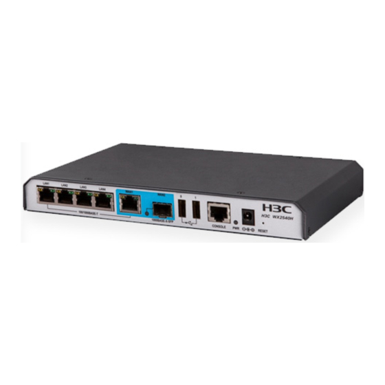
Appendix A Chassis views and technical specifications Chassis views Figure 1 Front view (1) 100/1000Base-T autosensing Ethernet copper ports 1 to 5 (2) 1000Base-X SFP fiber port (3) USB ports (4) Console port (5) Power adapter receptacle (6) Reset button (RESET) Figure 2 Rear view (1) Grounding screw Transceiver module, fiber connector, and optical... -
Page 34: Technical Specifications
Figure 3 SFP transceiver module Figure 4 Optical fiber with LC-type connector (1) LC-type connector (2) Optical fiber Technical specifications Table 1 Technical specifications Item Specification Console port One, 9600 bps (default) to 115200 bps Gigabit Ethernet port 5 x 100/1000 Base-T autosensing Ethernet copper port SFP port 1 x 100Base-FX/1000Base-X SFP fiber port Memory... -
Page 35: Transceiver Module Specifications
Item Specification System power consumption 8 W to 15 W Weight 0.9 kg (1.98 lb) Operating temperature 0°C to 40°C (32°F to 104°F) Relative humidity (noncondensing) 5% to 95% Transceiver module specifications A transceiver module that has MM in its name supports multi-mode optical fibers. A transceiver module that has SM in its name supports single-mode optical fibers. -
Page 36: Interface Arrangement
Table 4 SFP-GE-LH40-SM1310 specifications Item Specification Central wavelength 1310 nm Max transmission distance 40 km (24.86 miles) Transmission rate 1250 Mbps Connector type Duplex LC Fiber mode Fiber diameter 9 μm Transmit power –2 to +5 dBm Receive sensitivity ≤ –22 dBm Saturation ≤... - Page 37 Contents Appendix B LEDs ·························································································································································· 1 LEDs ···················································································································································································· 1...
- Page 38 Appendix B LEDs LEDs Figure 1 LEDs (1) 100/1000Base-T autosensing Ethernet copper port status LEDs (yellow) (2) 100/1000Base-T autosensing Ethernet copper port status LEDs (green) (3) 1000Base-X SFP fiber port status LED (4) Power status LED (PWR) Table 1 LED description Mark Status Description...
- Page 39 Mark Status Description Steady green A 1000 Mbps link is present on the port. 1000Base-X SFP fiber The port is receiving or transmitting data at Flashing green port status LED 1000 Mbps. No link is present on the port.
Need help?
Do you have a question about the WX2540E and is the answer not in the manual?
Questions and answers