H3C WX2540H Installation Manual
Hide thumbs
Also See for WX2540H:
- User configuration manual (57 pages) ,
- Configuration manual (11 pages)

Related Manuals for H3C WX2540H


Summary of Contents for H3C WX2540H
- Page 1 H3C WX2540H Access Controller Installation Guide New H3C Technologies Co., Ltd. http://www.h3c.com.hk Document version: 6W101-20170414...
- Page 2 Copyright © 2015-2017, New H3C Technologies Co., Ltd. and its licensors All rights reserved No part of this manual may be reproduced or transmitted in any form or by any means without prior written consent of New H3C Technologies Co., Ltd.
- Page 3 Preface The H3C WX2540H Access Controller Installation Guide describes preparing for installation, installing the access controller, troubleshooting, and hardware management and maintenance of the WX2540H access controller. This preface includes the following topics about the documentation: Audience. • Conventions. •...
- Page 4 GUI conventions Convention Description Window names, button names, field names, and menu items are in Boldface. For Boldface example, the New User window opens; click OK. > Multi-level menus are separated by angle brackets. For example, File > Create > Folder. Symbols Convention Description...
- Page 5 It is normal that the port numbers, sample output, screenshots, and other information in the examples differ from what you have on your device. Obtaining documentation To access the most up-to-date H3C product documentation, go to the H3C website at http://www.h3c.com.hk. To obtain information about installation, configuration, and maintenance, click http://www.h3c.com.hk/Technical_Documents...
-
Page 6: Table Of Contents
Contents Preparing for installation ············································································································································· 1 Safety recommendations ·················································································································································· 1 General safety recommendations ··························································································································· 1 Electrical safety ························································································································································· 1 Laser safety ································································································································································ 2 Examining the installation site ········································································································································· 2 Temperature and humidity ······································································································································· 2 ... - Page 7 Rebooting the device ····················································································································································· 22 Rebooting the device immediately at the CLI ····································································································· 23 Scheduling a device reboot ································································································································· 23 Appendix A Chassis views and technical specifications ························································································ 24 Chassis views ································································································································································· 24 Transceiver module, fiber connector, and optical fiber views ·················································································· 24 ...
-
Page 8: Preparing For Installation
Preparing for installation Safety recommendations To avoid any equipment damage or bodily injury, read the following safety recommendations before installation. Note that the recommendations do not cover every possible hazardous condition. General safety recommendations • Do not place the device on an unstable case or desk. The device might be severely damaged in case of a fall. -
Page 9: Laser Safety
Laser safety WARNING! Do not stare into any fiber port when the device is powered on. The laser light emitted from the fiber port might hurt your eyes. Before you disconnect a fiber connector, execute the shutdown command in interface view to •... -
Page 10: Cooling
The equipment room must also meet limits on salts, acids, and sulfides to eliminate corrosion and premature aging of components, as shown in Table Table 3 Harmful gas limits in the equipment room Max. (mg/m 0.006 0.05 0.01 Cooling Leave a minimum of 10 cm (3.94 in) of clearance around the device. •... -
Page 11: Lightning Protection
Use electromagnetic shielding, for example, shielded interface cables, when necessary. • Lightning protection To protect the device from lightning, follow these guidelines: Make sure the chassis is reliably grounded by using the grounding cable. • Make sure the grounding terminal of the AC power receptacle is reliably grounded. •... - Page 12 Item Requirements Result • The chassis is reliably grounded. Lightning • The grounding terminal of the AC power receptacle is protection reliably grounded. • Equip a UPS. Electricity safety • In case of emergency during operation, switch off the external power switch. Safety The device is far away from any moist area and heat source.
-
Page 13: Installing The Device
WARNING! Keep the tamper-proof seal on a mounting screw on the chassis cover intact, and if you want to open the chassis, contact H3C Support for permission. Otherwise, H3C shall not be liable for any consequence. Confirming installation preparations Before you install the device, verify that you have read "Preparing for... -
Page 14: Mounting The Device On A Workbench
Mounting the device on a workbench IMPORTANT: Do not place heavy objects on the device. To mount the device on a workbench: Place the device with bottom up and clean the round holes in the chassis bottom. Attach the rubber feet to the four round holes in the chassis bottom. Place the device with upside up on the workbench. -
Page 15: Connecting The Grounding Cable To The Device
Figure 3 Attaching the ring terminal to the grounding cable Heat-shrink Grounding cable Ring terminal tubing 5 mm (0.20 in) Connecting the grounding cable to the device Use a Phillips screwdriver to remove the grounding screw from the rear panel of chassis. Use the grounding screw to attach the ring terminal of the grounding cable to the chassis. -
Page 16: Setting Terminal Parameters
Connect the console cable: Plug the DB-9 female connector of the console cable to the serial port of the PC. Connect the RJ-45 connector to the console port of the device. Figure 5 Connecting the console cable NOTE: Identify the mark on the console port and make sure you are connecting to the correct port. •... - Page 17 Figure 6 Connection description Select the serial port to be used from the Connect using list, and click OK. Figure 7 Setting the serial port used by the HyperTerminal connection Set Bits per second to 9600, Data bits to 8, Parity to None, Stop bits to 1, and Flow control to None, and click OK.
- Page 18 Figure 8 Setting the serial port parameters Select File > Properties in the HyperTerminal window. Figure 9 HyperTerminal window On the Settings tab, set the emulation to VT100 or Auto detect and click OK.
-
Page 19: Connecting The Ethernet Cables
Figure 10 Setting the terminal emulation in Test Properties dialog box Connecting the Ethernet cables Connecting a copper Ethernet port Connect one end of the Ethernet cable to the copper Ethernet port on the device, and the other end to the Ethernet port on the peer device. After powering on the device, examine the LEDs of the fixed copper Ethernet port. -
Page 20: Connecting The Power Adapter
Remove the dust plug from the fiber port. Remove the dust cover from the transceiver module, and insert the transceiver module into the fiber port. Remove the dust covers from the optical fiber connector. Identify the Rx and Tx ports on the transceiver module. Use the optical fiber to connect the Rx port and Tx port on the transceiver module to the Tx port and Rx port on the peer end, respectively. -
Page 21: Verifying The Installation
Booting Normal Extended BootWare The Extended BootWare is self-decompressing........Done. **************************************************************************** H3C WX2540H BootWare, Version 5.08 **************************************************************************** Copyright (c) 2004-2017 New H3C Technologies Co., Ltd. Compiled Date : May 26 2017 CPU Type : 1200MHz Multi-core Processor Memory Type : DDR3 SDRAM... - Page 22 BootWare Size : 640KB Flash Size : 1024MB CPLD Version : 002 PCB Version : Ver.B BootWare Validating... Press Ctrl+B to access EXTENDED-BOOTWARE MENU... Press Ctrl + B at the prompt within 4 seconds to access the Boot menu. Otherwise, the system enters the system image file reading and self-compressing process.
- Page 23 Line con0 is available. Press ENTER to get started. Press Enter at the prompt, and you can configure the device when the prompt <H3C> appears. During the startup process, the CPLD is automatically upgraded to the latest version.
-
Page 24: Troubleshooting
Verify that the power source specifications are as required. Verify that the power cord is securely connected to the device. Verify that the power cord is in good condition. If the problem persists, contact H3C Support. No display or garbled display on the configuration terminal Symptom The configuration terminal does not have display or displays garbled text after the device is powered on. -
Page 25: Software Loading Failure
Verify that the console cable is not faulty. If the problem persists, contract H3C Support. Software loading failure Symptom Software loading fails. Resolution To resolve the problem: Verify that the physical ports are correctly connected. If the cable of any port is not connected, re-connect the cable to the port, and make sure the physical connection is correct. -
Page 26: Hardware Management And Maintenance
H3C Comware Software, Version 7.1.064, Release 5323 Copyright (c) 2004-2017 New H3C Technologies Co., Ltd. All rights reserved. H3C WX2540H uptime is 0 weeks, 0 days, 0 hours, 22 minutes Last reboot reason : User soft reboot Boot image: flash:/boot.bin Boot image version: 7.1.064, Release 5323... -
Page 27: Displaying Detailed Information About The Device
===============display version=============== H3C Comware Software, Version 7.1.064, Release 5323 Copyright (c) 2004-2017 New H3C Technologies Co., Ltd. All rights reserved. H3C WX2540H uptime is 0 weeks, 0 days, 0 hours, 27 minutes Last reboot reason : User soft reboot …... -
Page 28: Displaying The Cpu Usage Of The Device
<H3C> display device manuinfo DEVICE_NAME:WX2540H DEVICE_SERIAL_NUMBER:210235A1JMC166000028 MAC_ADDRESS:84D9-3110-9FD8 MANUFACTURING_DATE:2016-06-04 VENDOR_NAME:H3C Table 6 Command output Field Description DEVICE_NAME Device model. DEVICE_SERIAL_NUMBER Serial number of the device. MAC_ADDRESS MAC address of the device. MANUFACTURING_DATE Manufacturing data of the device. VENDOR_NAME Vendor name. Displaying the CPU usage of the device Use the display cpu-usage command to display the CPU usage statistics for the device. -
Page 29: Rebooting The Device
If a startup configuration file or software image problem exists, the device cannot start up correctly. For more information about the two display H3C WX2540H Access Controller Fundamentals Command Reference commands, see The following methods are available for rebooting the device: Reboot the device at the CLI. -
Page 30: Rebooting The Device Immediately At The Cli
Rebooting the device immediately at the CLI Perform the following task in user view: Task Command Reboot the device immediately. reboot [ force ] Scheduling a device reboot Task Command Remarks Available in user view. Specify the reboot date schedule reboot at time [ date ] By default, no reboot date or time and time. -
Page 31: Appendix A Chassis Views And Technical Specifications
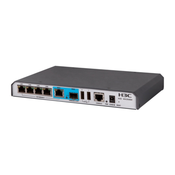
Appendix A Chassis views and technical specifications Chassis views Figure 13 Front view (1) 100/1000Base-T autosensing Ethernet copper ports 1 to 5 (2) 1000Base-X SFP fiber port (3) USB ports (4) Console port (5) Power adapter receptacle (6) Reset button (RESET) Figure 14 Rear view (1) Grounding screw Transceiver module, fiber connector, and optical... -
Page 32: Technical Specifications
Figure 15 SFP transceiver module Figure 16 Optical fiber with LC-type connector (1) LC-type connector (2) Optical fiber Technical specifications Table 9 Technical specifications Item Specification Console port One, 9600 bps (default) to 115200 bps Gigabit Ethernet port 5 x 100/1000 Base-T autosensing Ethernet copper port SFP port 1 x 100Base-FX/1000Base-X SFP fiber port Memory... -
Page 33: Transceiver Module Specifications
Item Specification System power consumption 8 W to 15 W Weight 0.9 kg (1.98 lb) Operating temperature 0°C to 40°C (32°F to 104°F) Relative humidity (noncondensing) 5% to 95% Transceiver module specifications A transceiver module that has MM in its name supports multi-mode optical fibers. A transceiver module that has SM in its name supports single-mode optical fibers. -
Page 34: Interface Arrangement
Table 12 SFP-GE-LH40-SM1310 specifications Item Specification Central wavelength 1310 nm Max transmission distance 40 km (24.86 miles) Transmission rate 1250 Mbps Connector type Duplex LC Fiber mode Fiber diameter 9 μm Transmit power –2 to +5 dBm Receive sensitivity ≤ –22 dBm Saturation ≤... -
Page 35: Appendix B Leds
Appendix B LEDs LEDs Figure 17 LEDs (1) 100/1000Base-T autosensing Ethernet copper port status LEDs (yellow) (2) 100/1000Base-T autosensing Ethernet copper port status LEDs (green) (3) 1000Base-X SFP fiber port status LED (4) Power status LED (PWR) Table 14 LED description Mark Status Description... - Page 36 Mark Status Description Steady green A 1000 Mbps link is present on the port. 1000Base-X SFP fiber The port is receiving or transmitting data at 1000 Flashing green port status LED Mbps. No link is present on the port.
-
Page 37: Index
Index electronic label data display (on controller engine), electronic label data display (on switching installation, engine), installation flow, fiber port connection, troubleshooting power supply failure, grounding, AC power adapter, information display (on controller engine), adapter information display (on switching engine), AC power, installation verification, DC power,... - Page 38 environment installation site, installing site cleanliness, site cooling requirements, AC installation flow, site dust concentration, checklist, site gas saturation, cooling requirements, site humidity, EMI prevention, site temperature, ESD prevention, ESD prevention, installation verification, Ethernet copper port connection, lightning protection, examining installation site, site cleanliness, site examination, site humidity,...
- Page 39 operational statistics display, device grounding, optical fiber electrical safety recommendations, views, EMI prevention, ESD prevention, general recommendations, parameter installation site cleanliness, terminal parameter setting, installation site dust concentration, port installation site gas saturation, copper Ethernet port connection, installation site humidity, fiber port connection, installation site temperature, power cooling requirements,...
- Page 40 parameter setting, transceiver module technical specifications, views, troubleshooting device, power supply failure, software loading failure, ventilation (installation site), verifying installation, workbench device mount,...
Need help?
Do you have a question about the WX2540H and is the answer not in the manual?
Questions and answers