
Related Manuals for H3C WX3840X


Summary of Contents for H3C WX3840X
- Page 1 H3C WX3840X Access Controller Installation Guide New H3C Technologies Co., Ltd. http://www.h3c.com Document version: 5W101-20221223...
- Page 2 The information in this document is subject to change without notice. All contents in this document, including statements, information, and recommendations, are believed to be accurate, but they are presented without warranty of any kind, express or implied. H3C shall not be liable for technical or editorial errors or omissions contained herein.
- Page 3 Preface This installation guide describes the installation procedures for the H3C WX3840X access controller, including preparing for installing the controller, installing and accessing the controller, troubleshooting the controller, and maintaining the controller. This preface includes the following topics about the documentation: •...
- Page 4 It is normal that the port numbers, sample output, screenshots, and other information in the examples differ from what you have on your device. Documentation feedback You can e-mail your comments about product documentation to info@h3c.com. Your comments or suggestions would be highly appreciated.
-
Page 5: Table Of Contents
Contents 1 Preparing for installation ·········································································· 1-1 Safety recommendations ································································································································ 1-1 Safety symbols ········································································································································ 1-1 General safety recommendations ··········································································································· 1-1 Electrical safety ······································································································································· 1-1 Laser safety ············································································································································· 1-2 Examining the installation site ························································································································· 1-2 Temperature and humidity ······················································································································ 1-2 Cleanliness ·············································································································································· 1-2 Cooling ····················································································································································... -
Page 6: Preparing For Installation
Preparing for installation Safety recommendations To avoid any equipment damage or bodily injury, read the following safety recommendations before installation. Note that the recommendations do not cover every possible hazardous condition. Safety symbols When reading this document, note the following symbols: WARNING means an alert that calls attention to important information that if not understood or followed can result in personal injury. -
Page 7: Laser Safety
Laser safety WARNING! Do not stare into any open apertures of operating transceiver modules or optical fiber connectors. The laser light emitted from these apertures might hurt your eyes. CAUTION: • Before you remove the optical fiber connector from a fiber port, execute the shutdown command in interface view to shut down the port. -
Page 8: Cooling
To eliminate corrosion and premature aging of components, the equipment room must also meet limits on salts, acids, and sulfides, as shown in Table1-3. Table1-3 Harmful gas limits in an equipment room Max. (mg/m 0.006 0.05 0.01 0.04 Cooling The device uses left-to-right airflow. For adequate heat dissipation of the device, follow these guidelines: •... -
Page 9: Emi
No ESD wrist strap is provided with the device. Prepare one yourself. To attach an ESD wrist strap: Wear the wrist strap on your wrist. Lock the wrist strap tight around your wrist to maintain good contact with the skin. Secure the wrist strap lock and the alligator clip lock together. -
Page 10: Lightning Protection
• Use electromagnetic shielding, for example, shielded interface cables, when necessary. • To prevent signal ports from getting damaged by overvoltage or overcurrent caused by lightning strikes, route interface cables only indoors. If you must route interface cables outdoors, install network port lightning protectors. -
Page 11: Pre-Installation Checklist
Pre-installation checklist Table1-4 Pre-installation checklist Item Requirements Result • There is a minimum clearance of 100 mm (3.94 in)) around the device for heat dissipation. Ventilation • A good ventilation system is available at the installation site. 0°C to 45°C (32°F to 113°F) Temperature 5% RH to 95% RH (noncondensing) Humidity... - Page 12 Contents 2 Installing the device ················································································· 2-1 Confirming installation preparations ················································································································ 2-1 Installation flowchart········································································································································ 2-2 Mounting the device on a workbench ············································································································· 2-3 Installing the device in a 19-inch rack ············································································································· 2-3 Installing the device in a 19-inch rack ············································································································· 2-3 Mounting brackets ···································································································································...
-
Page 13: Installing The Device
WARNING! Keep the tamper-proof seal on a mounting screw on the chassis cover intact, and if you want to open the chassis, contact H3C Support for permission. Otherwise, H3C shall not be liable for any consequence caused thereby. Confirming installation preparations Before you install the device, verify that you have read "Preparing for installation"... -
Page 14: Installation Flowchart
Installation flowchart Figure2-1 Installation flowchart Start Determine the installation position Install the device on Install the device in a workbench a 19-inch rack Ground the device (Optional) Install network port lightning protectors (Optional) Install a surge protected power strip Connect the device to the network Installing an expansion module... -
Page 15: Mounting The Device On A Workbench
Mounting the device on a workbench CAUTION: Do not place heavy objects on the device. If a standard 19-inch rack is not available, you can mount the device on an anti-static workbench in the equipment room. To mount the device on a workbench: Place the device upside down. -
Page 16: Mounting Brackets
• Installing the device by using front mounting brackets and a rack shelf. • Installing the device by using front mounting brackets and slide rails. Mounting brackets Figure2-3 Front mounting bracket Figure2-4 Rear mounting bracket Installing the device by using front and rear mounting brackets Wear the ESD wrist strap and make sure the rack is sturdy and is reliably grounded. - Page 17 The shoulder screws will be in close contact with the rear mounting brackets to support the device. Figure2-6 Attaching the front mounting brackets to the device According to the device installation position in the rack, use screws and cage nuts to attach the rear mounting brackets to the rear rack posts.
-
Page 18: Installing The Device By Using Front Mounting Brackets And A Rack Shelf
the front rack posts with screws and cage nuts, as shown in Figure2-8. Make sure the load-bearing screws are in close contact with the upper edges of the rear mounting brackets. Figure2-8 Installing the device in the rack Installing the device by using front mounting brackets and a rack shelf The rack shelf is an optional component that needs to be separately ordered if needed. - Page 19 Figure2-9 Installing the rack shelf Place the device on the rack shelf and push the device in the rack. Attach the front mounting brackets on the device to the front rack posts by using M6 screws and cage nuts, as shown in Figure2-10.
-
Page 20: Installing The Device By Using Front Mounting Brackets And Slide Rails
Installing the device by using front mounting brackets and slide rails The slide rails are optional components that need to be separately ordered if needed. The slide rails in this example are for illustration only. To install the device by using front mounting brackets and slide rails: Wear the ESD wrist strap and verify that the rack is sturdy and is reliably grounded. -
Page 21: Grounding The Device
Figure2-12 Installing the device in the rack Attach the front mounting brackets on the device to the front rack posts with M6 screws and cage nuts. Grounding the device WARNING! • Correctly connecting the grounding cable is crucial to lightning protection and EMI protection. Before installing or using the device, connect the grounding cable for it correctly. - Page 22 Figure2-13 Grounding the device by using a grounding strip Grounding the device through the rack If the device is installed in a rack, you can connect the other end of the grounding cable to the grounding point on the rack. Make sure the rack is grounded reliably. 2-10...
- Page 23 Figure2-14 Grounding the device through the rack Grounding the device with a grounding conductor buried in the earth If earth is available at the installation site, you can ground the device with a grounding conductor buried in the earth. Hammer a 0.5 m (1.64 ft) or longer angle iron or steel tube into the earth to serve as a grounding conductor.
-
Page 24: (Optional) Installing Network Port Lightning Protectors
Figure2-15 Grounding the device by burying the grounding conductor into the earth (Optional) Installing network port lightning protectors CAUTION: If part of the network cable for a network port is routed outdoors, install a network port lightning protector for the port to protect against damages caused by lightning strikes. IMPORTANT: •... -
Page 25: (Optional) Installing A Surge Protected Power Strip
Figure2-16 Installing a lightning protector for a network port (Optional) Installing a surge protected power strip CAUTION: If you use an AC power line routed from outdoors for the device, use a surge protected power strip for the device to protect against damages caused by lightning strikes. IMPORTANT: Before installing a surge protected power strip, read the instructions in the document that comes with the strip. -
Page 26: Connecting The Device To The Network
Connecting the device to the network Connecting Ethernet cables Connecting an Ethernet copper port Connect one end of the Ethernet cable to the Ethernet copper port on the device, and the other end to the Ethernet port on the peer device. After powering on the device, examine the LEDs of the fixed Ethernet copper port. -
Page 27: Installing An Expansion Module
Figure2-17 Connecting an optical fiber Installing an expansion module CAUTION: Do not hot swap expansion modules. The device does not come with any expansion modules. Purchase expansion modules as needed. Installing an expansion module on the front panel You can install EWPXM1XG03 expansion modules in slot 3 in the front panel. To install an expansion module: Wear an ESD wrist strap and make sure it makes good skin contact and is reliably grounded. -
Page 28: Installing An Expansion Module On The Rear Panel
Figure2-18 Installing an expansion module Installing an expansion module on the rear panel You can install EWPXM1XG20 expansion modules in slot 1 or slot 2 in the rear panel. To install an expansion module, for example, EWPXM1XG20 in slot 1: Use a Phillips screwdriver to remove the screws on the filler panel and then remove the filler panel. -
Page 29: Installing A Drive
Figure2-19 Installing an expansion module Installing a drive CAUTION: Do not hot swap drives. The device does not come with any drives. Purchase drives as needed. To install a drive: Wear an ESD wrist strap and make sure it makes good skin contact and is reliably grounded. Remove the filler panel from the drive slot. -
Page 30: Installing A Power Supply
Installing a power supply CAUTION: Do not install an AC power supply and a DC power supply on the same device. Remove the filler panel (if any) from the slot where you want to install a power supply with a Phillips screwdriver. -
Page 31: Connecting An Ac Power Cord
To avoid bodily injury, first connect the power cord to the device, and then connect the power cord to the power source in the equipment room. CAUTION: Before connecting the power cord, make sure the device is grounded correctly. Connecting an AC power cord: Connect one end of the AC power cord to the AC-input power receptacle on the device. -
Page 32: Verifying The Installation
Power on the device. The device initializes its memory and runs the BootWare. The following information appears on the terminal screen: System is Starting..Press Ctrl+D to access BASIC-BOOTWARE MENU Press Ctrl+T to access BOOTWARE DIAG-TEST MENU Booting Normal Extend Bootware **************************************************************************** H3C WX3840X BootWare, Version 1.12 2-20... - Page 33 Line con0 is available. Press ENTER to get started. Press Enter at the prompt, and you can configure the device when the prompt <H3C> appears. NOTE: If a new CPLD version is available, the device updates its CPLD version automatically.
- Page 34 Contents Log in to the device ························································································ 1 Log in through Telnet or SSH····························································································································· 1 Configure Telnet login ································································································································ 1 Configure SSH login ··································································································································· 1 Log in through the console port·························································································································· 1 About this task ············································································································································ 1 Prerequisites ·············································································································································· 1 Configure terminal parameters ···················································································································...
- Page 35 Log in to the device You can log in to a device through Telnet, SSH, or the Console port, or from the Web interface. • Telnet/SSH login—Log in to the device through a remote connection to configure or manage the device. •...
- Page 36 • When you disconnect a PC from the device, first remove the RJ-45 connector and then remove the DB-9 connector as a best practice. • If the PC does not have an RS-232 interface but has an USB port, use a USB-to-RS-232 adapter to connect the console cable.
- Page 37 Procedure To log in to the device from the Web interface through a wired connection: Visit the default IP address 192.168.0.100 to access the local Web interface. Enter the default username and password, and then click the login button. For security purposes, change the login password as prompted.
- Page 38 Contents 3 Troubleshooting ······················································································· 3-1 Power supply failure ········································································································································ 3-1 Symptom ················································································································································· 3-1 Solution ··················································································································································· 3-1 No display or garbled display on the configuration terminal ··········································································· 3-1 Symptom ················································································································································· 3-1 Solution ··················································································································································· 3-1 Software loading failure··································································································································· 3-2 Symptom ················································································································································· 3-2 Solution ···················································································································································...
- Page 39 Troubleshooting Power supply failure Symptom The device cannot be powered on. The power supply status LED (PWR) is off, or the system status LED (SYS) is off. Solution To resolve the issue: Verify that the power source is as required. Verify that the power cord is connected securely.
- Page 40 Software loading failure Symptom The device fails in software loading. Solution To resolve the issue: Verify that the physical ports are connected securely and correctly. If a port is not connected securely, reconnect the port and make sure the connections are correct. View the software loading process displayed on the HyperTerminal to check for errors.
- Page 41 Contents 4 Hardware management and maintenance ··············································· 4-1 Displaying hardware information about the device ························································································· 4-1 Displaying software and hardware version information about the device ··············································· 4-1 Displaying the operational statistics about the device············································································· 4-2 Displaying information about the device ································································································· 4-3 Displaying electrical label information for the device ··············································································...
-
Page 42: Hardware Management And Maintenance
<H3C> display version H3C Comware Software, Version 9.1.053, ESS 1054 Copyright (c) 2004-2022 New H3C Technologies Co., Ltd. All rights reserved. H3C WX3840X uptime is 0 weeks, 0 days, 0 hours, 22 minutes Last reboot reason : Power on Boot image: flash:/boot.bin Boot image version: 9.1.053, ESS 1054... -
Page 43: Displaying The Operational Statistics About The Device
===============display version=============== H3C Comware Software, Version 9.1.053, ESS 1054 Copyright (c) 2004-2022 New H3C Technologies Co., Ltd. All rights reserved. H3C WX3840X uptime is 0 weeks, 0 days, 0 hours, 27 minutes Last reboot reason : Power on Boot image: flash:/boot.bin Boot image version: 9.1.053, ESS 1054... -
Page 44: Displaying Information About The Device
Basic Bootrom Version is 1.12 Extend Bootrom Version is 1.12 [Subslot 0]WX3840X Hardware Version is Ver.A … Displaying information about the device Use the command to display information about the device. display device <H3C> display device Slot No. Subslot No. Board Type... -
Page 45: Displaying The Memory Usage Of The Device
<H3C> display cpu-usage Unit CPU usage: 0% in last 5 seconds 0% in last 1 minute 4% in last 5 minutes Table4-3 Command output Field Description Unit CPU usage CPU usage information Average CPU usage in the last 5 seconds (after the device boots, the device 0% in last 5 seconds calculates and records the average CPU usage at the interval of 5 seconds). -
Page 46: Displaying The Operational Status Of The Built-In Fans
Displaying the operational status of the built-in fans Use the display fan command to display the operating states of fans. <H3C> display fan Fan 1 State: Normal Fan 2 State: Normal Fan 3 State: Normal Fan 4 State: Normal Fan 5 State: Normal... -
Page 47: Restrictions And Guidelines
Restrictions and guidelines • Before you reboot the device, perform the following tasks: Use the command to save the running configuration. For more information about the save command, see configuration file management commands in the command save references. Use the commands to verify that you display startup display boot-loader... - Page 48 Contents 5 Chassis views and technical specifications ·············································· 5-1 Chassis views ················································································································································· 5-1 Power supply views········································································································································· 5-2 AC power supply ····································································································································· 5-2 DC power supply ····································································································································· 5-2 Interface arrangement ····································································································································· 5-2 Technical specifications ·································································································································· 5-3...
-
Page 49: Chassis Views And Technical Specifications
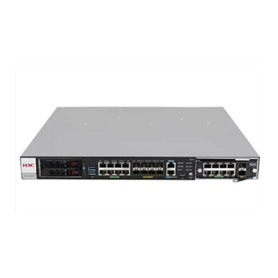
Chassis views and technical specifications Chassis views Figure5-1 Front view (1) Drive slot (2) USB port (3) 100/1000BASE-T autosensing Ethernet ports 1 through 7 (4) 1000BASE-X SFP ports 9 through 16 (5) Console port (6) Expansion slot (8) 100/1000BASE-T out-of-band (7) Reset button (RESET) Ethernet port IMPORTANT:... -
Page 50: Power Supply Views
Power supply views AC power supply Figure5-3 AC power supply (1) Power receptacle (2) Air outlet vent DC power supply Figure5-4 DC power supply (1) Power receptacle (2) Air outlet vent Interface arrangement The access controller provides fixed interfaces GigabitEthernet 1/0/1 through GigabitEthernet 1/0/16. You can identify an interface by its mark. -
Page 51: Technical Specifications
Technical specifications Table5-1 Technical specifications Item Specification Console port 1, 9600 bps (default) to 115200bps GE port 8 × 100/1000BASE-T autosensing Ethernet ports Management port 1 × 100/1000BASE-T management Ethernet port SFP port 8 × 1000BASE-X SFP ports • To restore the device to factory default settings, press and hold the button for more than 5 seconds. - Page 52 Contents 6 LEDs ········································································································ 6-1 LEDs ······························································································································································· 6-1 LED description ··············································································································································· 6-1...
- Page 53 LEDs LEDs Figure6-1 LEDs (1) 100/1000BASE-T autosensing Ethernet port LEDs (2) 1000BASE-X SFP port LED (3) Power module LED (PWR1) (4) Power module LED (PWR2) (5) System status LED (SYS) (6) Expansion module status LED (SLOT1) (7) Expansion module status LED (SLOT2) (8) Expansion module status LED (SLOT3) (9) 100/1000BASE-T out-of-band management Ethernet port status LED (LINK/ACT) LED description...
- Page 54 Mark Status Description SLOT3 No expansion module is present. Steady green The drive is present and operating correctly. Data is being read from or written to the Drive status LED Fast flashing green drive. No drive is present. Steady green A link is present.
- Page 55 Contents 7 Optional transceiver modules ·································································· 7-1 Views······························································································································································· 7-1 Specifications ·················································································································································· 7-1...
- Page 56 A transceiver module that has "MM" in its name supports multi-mode optical fibers. A transceiver module that has "SM" in its name supports single-mode optical fibers. The H3C transceiver modules are subject to change over time. For the most recent list of H3C transceiver modules, contact Technical Support or marketing staff.
- Page 57 Item SFP-GE-SX-MM850-A Connector type Duplex LC connector Fiber mode 50 μm Fiber diameter Output power –9.5 to 0 dBm ≤ –17 dBm Receiver sensitivity ≤ –3 dBm Light saturation Table7-2 SFP-GE-LX-SM1310-A specifications Item SFP-GE-LX-SM1310-A Central wavelength 1310 nm Max transmission distance 10 km (6.21 miles) Data rate 1250 Mb/s...
Need help?
Do you have a question about the WX3840X and is the answer not in the manual?
Questions and answers