Table of Contents
Advertisement
Quick Links
INSTRUCTIONS
DP2-SAL
Standalone connection kit
This instruction manual is for the standalone connection kit for Olympus microscope
digital camera.
To obtain optimum performance of this system and to ensure the safety, study this
manual thoroughly before operating the system and keep it on hand during operation
of this system.
Keep this instruction manual in a safe place.
For details of products included in the configuration of this system, see page 8 of this
Optical Microscope Accessory
instruction manual.
Advertisement
Table of Contents

Subscribe to Our Youtube Channel
Related Manuals for Olympus DP2-SAL


Summary of Contents for Olympus DP2-SAL
- Page 1 INSTRUCTIONS DP2-SAL Standalone connection kit This instruction manual is for the standalone connection kit for Olympus microscope digital camera. To obtain optimum performance of this system and to ensure the safety, study this manual thoroughly before operating the system and keep it on hand during operation of this system.
- Page 2 Refer to your local Olympus distributor in EU for return and/or collection systems available in your country. NOTE: This equipment has been tested and found to comply with the limits for a Class A digital device, pursuant to Part 15 of the FCC Rules.
-
Page 3: Table Of Contents
Contents Introduction ................................ Safety precautions ............................Handling precautions..........................1 System diagram ............................2 Nomenclature of respective portions ..................2-1 Hardware controls .............................. 9 2-2 Control window ..............................11 3 Assembly ............................... Installing the control box D2-CB ........................... 16 Connecting the interface cable ............................. 16 Connecting the display cable ............................ - Page 4 4-2 Basic settings ..............................29 Setting live image resolution ............................29 Setting still image resolution............................30 Setting still image format ..............................31 Setting ISO sensitivity ................................32 Setting white balance (WB) mode ..........................32 Setting metering area ................................33 Adjusting contrast ..................................33 Setting image color ..................................34 Setting sharpness ..................................34 4-3 Advanced operations ...........................
- Page 5 DP2-SAL Media setup ....................................49 Reset ........................................50 Display Off setting ..................................53 Camera Calibration ..................................54 5 Play ..................................5-1 Basic operations ............................... 57 Selecting play images ................................57 Display zoom/scroll..................................58 Playing movies ....................................58 Extracting frames from movies ............................59 Protect play image ..................................59 Deleting images ..................................60 5-2 Advanced operations ...........................
- Page 6 Installing special device driver ............................86 Canceling password lock of USB recording media..................88 8 Functions linked with microscope ..................8-1 Application conditions ..........................89 8-2 Connecting procedures ..........................90 8-3 Operating procedures ..........................92 9 Warning list ..............................10 Specifications ............................11 Troubleshooting ............................
-
Page 7: Introduction
Software license agreement If you use this product, you shall be deemed to have consented to the terms and conditions in “OLYMPUS END-USER LICENSE AGREEMENT”. “OLYMPUS END-USER LICENSE AGREEMENT” is included in F: EULA of the product. Please read it carefully before using the product. -
Page 8: Safety Precautions
} : Indicates commentary (for ease of operation and maintenance). CAUTION - Electric safety - Always use the AC adapter and the power cord provided by Olympus. If the proper AC adapter and the power cord are not used, the electric safety and the EMC (Electro-Magnetic Compatibility) performance of the device cannot be assured. - Page 9 Cautions are displayed at the areas where special cautions are required when in use and operation. Be sure to follow the instructions. Caution label Top surface of the control box D2-CB position When caution labels are dirty or peeled off, contact Olympus for replacement or inquiries.
-
Page 10: Handling Precautions
Handling precautions Intended use This product is intended to be used as an ancillary component for use with Olympus DP22 and DP27 cameras for capture and storage of digital images, but not for clinical diagnostic purposes. Cautions in use 1. This equipment is a precision instrument. Handle it with care and avoid subjecting it to a sudden or severe impact. - Page 11 SAL does not have a function to check viruses. Use your PC to check viruses.) · Make sure that there is no computer virus in the network or PC to which DP2-SAL is connected. · If by any chance, the computer virus is mixed or if there is a suspicion of contamination, turn OFF the main switch of the control box D2-CB and unplug the power cord from the outlet.
- Page 12 When viewing the acquired images saved in the recording media in NTFS format such as USB-HDD (external hard disk for connecting USB), etc. with PC, the acquisition date/time may not be correct. Set the same time zone to DP2-SAL and PC, or format the recording media such as USB-HDD, etc. in FAT32 format.
- Page 13 2. When disposing of this product, be sure to follow the regulations and rules of your local government. Particularly, note that the lithium ion coin battery (CR2032) is built in the control box D2-CB. For any inquiry, contact Olympus. 3. When smoking the room for cleaning, etc., move the DP2-SAL to a place not exposed to smoke.
-
Page 14: System Diagram
} The image color setup matching the microscope is required for faithful color reproduction. For details, refer to p.34. } Consult Olympus for the compatible microscope and camera adapter. } Do not use the interface cable for the other purpose than intended use. -
Page 15: Nomenclature Of Respective Portions
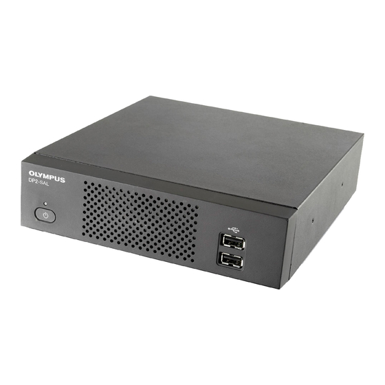
DP2-SAL Nomenclature of respective portions 2-1 Hardware controls Control box D2-CB Front Main switch USB connector (USB2.0) LAN cable connector Cable holder Back DC input connector RS-232C connector For connecting control box (U-CBS, etc.) (P.90) Display connector DVI-I/-D/-A USB connector (USB2.0) - Page 16 Upright stabilizer Stabilizer With 2 clamp screws AC adapter Output plug Input connector...
-
Page 17: Control Window
DP2-SAL 2-2 Control window Turn ON the main switch of the control box D2-CB to start the camera control software. The camera control software is displayed in the upper right area of the display window. In the Control window, Controller tab, Play tab, Info tab, and Menu tab are shown. - Page 18 Play tab 2 Window (P.61) The [Play] tab is used mainly for playing images. Erase (P.60) Measure (P.62) Thumbnail (P.57) Protect (P.59) Zoom (P.58) Playing movies (P.58) Still image format Exposure mode Info tab Number of remaining The [Info] tab is used for confirming the current settings or image properties. images Still image resolution File name...
- Page 19 DP2-SAL Menu tab The [Menu] tab is used for changing the settings. In [Menu] tab, there are [Camera control] tab, [Quality] tab, [Resolution] tab, [Display] tab, [Maintenance] tab and Setting tab. Camera control tab AE area (P.33) Display AE area (P.33) White balance (P.32)
- Page 20 Resolution tab Live image resolution (P.29) Still image resolution (P.30) Still image format (P.31) Sound of movie (P.42) Display tab Image orientation (P.43) Focus indicator (P.43) Scale (P.45) Scale orientation (P.45) Scale position (P.45)
- Page 21 DP2-SAL Maintenance tab Save in (P.46) File name (P.48) Media setup (P.49) Reset (P.50) Camera calibration (P.54) Microscope setting (P.78) Setting tab Time (P.82) Time zone (P.82) Display off setting (P.53) Language (P.78) Monitor resolution (P.83)
-
Page 22: Assembly
Connecting the interface cable · Always use the interface cable (USB 3.0 cable) provided by CAUTION Olympus. Using commercially available USB 3.0 cables or hubs does not guarantee the operations of the equipment. · The interface cable is vulnerable to bend or twist. -
Page 23: Connecting The Display Cable
DP2-SAL Connecting the display cable Connect the connector b of the display cable to the connector a of the control box D2-CB, and tighten the fixing screws. } Use a DVI cable matching the display as the display cable. When using a touch panel display The USB cable for the touch panel must be connected in addition to the display cable. -
Page 24: Connecting The Ac Adapter
· Always use the AC adapter and the power cord provided CAUTION by Olympus. Use of any other AC adapter may cause a malfunction. If the proper AC adapter and the power cord are not used, the electric safety and the EMC (Electro- Magnetic Compatibility) performance of the device cannot be assured. - Page 25 AC adapter. Also contact Olympus immediately. · Never use AC adapters which are not provided by Olympus. The control box D2-CB or the camera head may be damaged or an unexpected accident such as fire may occur.
-
Page 26: Connecting Usb Devices
For details, refer to "Setting save folders (P.46)". } When you use the USB mouse or the USB keyboard, prepare following devices satisfying compatibility standards or contact Olympus. USB mouse: Applicable for Windows 8 and USB 2.0 ®... -
Page 27: Lan Connection
DP2-SAL LAN Connection The LAN connection is necessary only when saving the acquired images by accessing the PC on the network from the control box D2-CB. When saving the acquired images to the recording media such as USB memory, etc., LAN connection is not necessary. -
Page 28: Acquisition
Acquisition 4-1 Basic operations This section describes the basic operating procedures (from turning ON the power to acquisition). You can acquire basic still images and movies only by descriptions in this section. } Perform the optical adjustment of the microscope sufficiently. } Use the camera adapter to perform the parfocal adjustment of the eyepiece of the microscope and the live image. -
Page 29: Start And Exit System
Press the [Shutdown] button d in the upper right area of the control window. The system is terminated and the power of the control box of DP2-SAL is turned OFF. (Time taken for shutdown: approximately 10 sec.) The LED b of the control box D2-CB and the LED c of the camera head are turned OFF. - Page 30 While operating the control box D2-CB, if the power of the camera head is turned OFF: Turn ON the main switch of the control box D2-CB to energize the camera head. While operating the control box D2-CB, if the interface cable is disconnected by mistake, the power of the camera head is turned OFF and it becomes the status that the camera head is not connected, and an error message appears.
-
Page 31: Selecting Exposure Mode
DP2-SAL Selecting exposure mode If the setting items of Submenu on the [Controller] tab are not displayed, Press [Submenu] a to open them. Press the [AE] button b to select "Auto" or "Manual". For procedures to set the exposure when "Manual" is selected, refer to "Manual exposure acquisition (P. -
Page 32: Acquiring Still Images
Acquiring still images Select the [Controller] tab a . Operate the microscope to frame the position you want to acquire and bring it into focus. Performing "Zoom the live image (P.38)" or "Display the focus indicator (P.43)" allows you to bring images into focus easily. Press the [Snap] button b to acquire and save images. -
Page 33: Roi White Balance
DP2-SAL ROI White Balance Adjusting the white balance before acquisition allows you to acquire images in appropriate colors. This product is equipped with the function to adjust the white balance automatically. This function is enabled in the initial setting. However, depending on light source types or specimens, the white balance cannot be adjusted automatically. -
Page 34: Setting Ae Lock
The system is terminated and the main switch of the control box of DP2-SAL is turned OFF. DP2-SAL is in sleep status (operations are paused). If you click the mouse or touch the touch panel display, DP2-SAL resumes operations immediately. -
Page 35: Basic Settings
DP2-SAL 4-2 Basic settings This section describes the settings related to acquisition. Setting live image resolution Select the [Menu] tab a and select the [Resolution] tab b in the tab displayed. Press the button of [Live image resolution] c to select resolutions described below in the list. -
Page 36: Setting Still Image Resolution
Setting still image resolution Select the [Menu] tab a and select the [Resolution] tab b in the tab displayed. Press the button of [Still image resolution] c to select resolutions described below in the list. DP22 DP27 High resolution 1920 x 1440 2448 x 1920 Low resolution 960 x 720... -
Page 37: Setting Still Image Format
DP2-SAL Setting still image format Select the [Menu] tab a and select the [Resolution] tab b in the tab displayed. Press the [Still image format] c button to select resolutions described below in the list. The file size for the file type per resolution is described below. -
Page 38: Setting Iso Sensitivity
Setting ISO sensitivity The ISO sensitivity can be set. The sensitivity is set based on the sensitivity of the photographic film. There are following types of sensitivity. The large the value is, the more it is suitable for acquiring dark specimens or fast-moving objects. DP22 DP27 ISO sensitivity 200, 400, 800... -
Page 39: Setting Metering Area
DP2-SAL Setting metering area When Auto exposure mode is selected: If the observation objects are scattered on the window, the full window may be too bright or too dark due to the influence from the background area excluding observation objects. This case may be improved by changing the metering area. -
Page 40: Setting Image Color
Setting image color You may be able to improve the color reproducibility of the live image and the acquired image by changing the image color according to the observation method. Button Function The color of the specimen is reproduced faithfully. High fidelity Use this color mode if no problem. -
Page 41: Advanced Operations
DP2-SAL 4-3 Advanced operations This section describes the advanced functions of DP2-SAL. With advanced functions, you can acquire the observed images suitable for your needs. Manual exposure acquisition The arbitrary exposure time is set manually to perform acquisition. Select the [Controller] tab a . -
Page 42: Recording Movie
Recording Movie Select the [Controller] tab a . Operate the microscope to frame the position you want to record and bring it into focus. Press the [Movie] button b to start recording the movie. While recording the movie, blinks and the recording time c is displayed. -
Page 43: Series Snap
DP2-SAL Series Snap The image can be acquired by the series snap interval as first as possible. The series snap interval is the time from the start of acquisition to the next acquisition. Select the [Controller] tab a . If the setting items of Submenu are not displayed, press [Submenu] b to open them. -
Page 44: Display Zoom/Scroll
Display zoom/scroll Select the [Controller] tab a . The digital zoom magnification changer can be changed by pressing button b . Button Function The image is zoomed in from 1x, 2x to 4x. The image is zoomed out from 4x, 2x to 1x. The image is displayed so that one pixel of the image is equivalent to one pixel of the display. -
Page 45: Selecting Zoom Magnification / Magnification Changer
DP2-SAL Selecting Zoom magnification / Magnification Changer Select the [Controller] tab a . If the setting items of Submenu are not displayed, press [Submenu] b to open them. Press the button of [Zoom/Mag. Changer] c to select the zoom magnification / magnification changer currently in the light path. -
Page 46: Advanced Settings
4-4 Advanced settings Setting AE area You can specify whether or not to display the metering area on the display. The metering area is shown with the yellow line on the display. For setting the metering area, refer to P.33. Select the [Menu] tab a and select the [Camera Control] tab b in the tab displayed. - Page 47 DP2-SAL When a message appears, set the objective to the light path of the microscope according to the message, and select [OK]. When a message appears, set the zoom/magnification changer to the light path of the microscope according to the message, and select [OK].
-
Page 48: Setting Sound Of Movie
Setting sound of movie Connect the microphone purchased separately to the microphone input terminal a of the control box D2-CB. Select the [Menu] tab b and select the [Resolution] tab c in the tab displayed. Press ON of [Sound of movie] d . Button Function The sound is included when... -
Page 49: Setting Image Orientation
DP2-SAL Setting image orientation The orientation of the image to be shown on the display can be set to either one of the followings. This operation is not available while saving the acquired image. Button Function Erect 180° rotated Left/Right inverted... - Page 50 Focus Indicator As a guide for focusing, the focused live image can be shown on the display. The focus indicator is displayed as a following bar in the lower area of the window. The meter’s maximum level is displayed automatically according to the contrast of the specimen. Normal view The current level is displayed in a blue bar.
-
Page 51: Setting Scale Display
DP2-SAL Setting scale display The scales can be added to the live image and the acquired image. In order to display the appropriate scale, the adapter CAUTION lens magnification, objective magnification and zoom/ magnification changer must be specified. Use the [Controller] tab for settings. -
Page 52: Setting Save Folders And File Names
Setting save folders and file names The save destination of the acquired image can be set. The save destinations you can set are recording media such as a USB memory, etc. or the PC connected to network. If multiple microscope digital cameras specify the same folders as those in the PC on the network and acquire images at the same time, an error that the acquired image cannot be saved may occur. - Page 53 DP2-SAL · If the USB is protected with a password and also the CAUTION save folder is protected by a password, the password protection must be disabled by the keyboard. For procedures to disable the password, refer to "Canceling password lock of USB recording media (P. 88)".
-
Page 54: Auto Save Folders And Auto File Names
Auto save folders and auto file names When the save destination is Auto: The acquired images are saved in the recording media connected to the control box D2-CB, e.g. USB memory, etc. If multiple recording media are connected, images are saved in the recording media connected first. -
Page 55: Media Setup
DP2-SAL Media setup All images in the save folder are deleted. When deleting images in a specified folder Select the [Menu] tab a and select the [Maintenance] tab b in the tab displayed. Press the [Erase all files] button c . -
Page 56: Reset
Only settings related to acquisition are returned to the factory default settings. The camera control software is returned to the factory default settings. The software of DP2-SAL and DP22/DP27-CU are updated. The version information of DP2-SAL and DP22/DP27- CU is confirmed. - Page 57 DP2-SAL Update the software. This function is used for updating DP2-SAL such as the firmware of the camera (items described in "Confirm the version information."). This function is not used normally. The system may be updated to improve the performances or vulnerability.
- Page 58 Menu tab - Resolution tab Live image resolution Still image resolution Still image format Sound of movie 1920 x 1440 (DP22), 1920 x 1440 (DP22), Reset JPEG-LOW 1224 x 960 (DP27) 2448 x 1920 (DP27) 1920 x 1440 (DP22), 1920 x 1440 (DP22), All Reset JPEG-LOW 1224 x 960 (DP27)
-
Page 59: Display Off Setting
DP2-SAL Display Off setting When DP2-SAL is not used for some time continuously, you can set the view on the display disappear temporarily. If you move the mouse when there is no view on the display, the view appears on the display again. -
Page 60: Camera Calibration
Camera Calibration If the brightness or the color of the left half of the live image is significantly different from those of the right half, the camera can be calibrated. Before calibrating the camera, place the specimen to bring it into focus in advance and remove the specimen. - Page 61 DP2-SAL Change the light path to the standard exposure status when using the camera, and press the [Next] button f . The calibration starts. } If the image is too bright or too dark, the message for urging you to take remedial action appears.
- Page 62 When the calibration is reset, the wizard window changes. Press the [Finish] button c .
-
Page 63: Play
DP2-SAL Play 5-1 Basic operations The functions used for playing images are aligned on the [Play] tab. You can view acquired images. Selecting play images The image to be played can be selected. Press the [Play] tab a to display the image which was acquired last in the folder specified as the save destination. -
Page 64: Display Zoom/Scroll
Display zoom/scroll The play image can be zoomed in. Also, arbitrary areas of the image can be displayed by scrolling. Select the [Play] tab a . Operate with the b button. Button Function The image is zoomed in from 1x, 2x to 4x. The image is zoomed out from 4x, 2x to 1x. -
Page 65: Extracting Frames From Movies
DP2-SAL Extracting frames from movies If the image selected in “Selecting play images (P.57)” is a movie, the frame currently displayed can be extracted as an image. Select the [Play] tab a . Select the movie ( ( ) you want to display from the thumbnail in the lower area of the display. -
Page 66: Deleting Images
Deleting images Unnecessary images can be deleted. Select the [Play] tab a . Select the image you want to delete from the thumbnail in the lower area of the window. Press the [Erase] button b . When the confirmation message appears, select [YES] if you want to delete. -
Page 67: Advanced Operations
DP2-SAL 5-2 Advanced operations 2 Window The selected still image and the live image are displayed side by side. Select the [Play] tab a . Press the [2 Window] button b . The selected still image is displayed on the right and the live image is displayed on the left. -
Page 68: Measurement
Measurement This section describes the operations using the mouse. If the touch panel display is connected, read the following operations as those on the right side. · "Click with mouse" (Left button) "Tap with finger" (Touch with finger and release) ·... - Page 69 DP2-SAL When measuring on the live image When measuring on the live image Select the [Controller] tab a . When measuring on the acquired image Select the [Play] tab a . The thumbnail is displayed. Select the image you want to measure.
- Page 70 [Measurement] window List of measurement functions Button Function Outline of functions Notes (Restrictions) Page Distance between 2 The distance between specified 2 Up to 20 measurement functions in P.66 points points are measured. total excluding Free line and Count can be performed. (Text and Arrow are included.) Up to 50 Free lines and Counts can be drawn respectively.
- Page 71 DP2-SAL Button Function Outline of functions Notes (Restrictions) Page Polygon area By creating the polygon, its area Up to 100 angles can be specified P.70 and circumference length are per polygon. measured. Free line The free lines can be drawn.
- Page 72 Distance between 2 points The distance between specified 2 points is measured. Select button. Click the mouse to specify the start point and the end point of the position you want to measure. You can measure another position continuously. Right-click the mouse on the window to finish.
- Page 73 DP2-SAL 3 points circle A circle is created (by inputting 3 points) on the image and the diameter and the area of the circle can be measured. Select button. Specify the position you want to measure using the circle. Click the mouse to specify 3 points that will be the circumference.
- Page 74 3 points angle Specify 3 points on the image and measure the angle. Select button. Click the mouse to specify 3 points to create the angle you want to measure. The internal angle of the intersection You can measure another position continuously. Right-click the mouse between 2 lines is displayed.
- Page 75 DP2-SAL Perpendicular By creating the line and then specifying one point, the perpendicular line is drawn from the specified point to the created line, and the length of the perpendicular line drawn is measured. Select button. Click the mouse on 2 arbitrary points to create the reference line (line passing 1 and 2 shown in the left picture).
- Page 76 Polygon area The polygon is created on the image and area and circumference length is measured. The polygon that can be created is up to the hectogon. Select button. A point is drawn at Click the mouse on arbitrary positions to draw the polygon. the specified position.
- Page 77 DP2-SAL XY distance The X distance, Y distance and L distance between specified 2 points are measured. A line connecting 1 and 2 is drawn. Select button. And the X distance, Y distance and L distance are displayed. Click the mouse to specify the start point and the end point of the position you want to measure.
- Page 78 Ruler A ruler can be drawn on the image. Select button. Click the mouse to specify the start point and the end point of the position you want to draw. You can draw another ruler continuously. Right-click the mouse on the window to finish.
- Page 79 DP2-SAL Count By drawing the marks at multiple locations on the image, the number of mark locations can be counted. Up to 50 marks can be drawn at the same time. } Even after the measurement is finished or other measurements are performed, marks can be displayed in sequential number if marks are not deleted.
- Page 80 Delete The measurement results on the window can be deleted. Select button. Click the mouse to specify measurement results you want to delete. If you select , the specified measurement results are deleted. } Multiple measurement results cannot be deleted at the same time. Delete all All measurement results on the window can be deleted at a time.
-
Page 81: Outputting Measurement Results In Csv File
DP2-SAL Outputting measurement results in CSV file The measurement results can be outputted to files in CSV format. Select the [ON] button a of [Save results]. Select the button b to close the [Measurement] window. Select the [Controller] tab c . -
Page 82: Setting Display Target Of Scales And Cross Lines
Setting display target of scales and cross lines When the display of scales or cross lines is set to ON, you can select from 2 types described below. Button Function Live Scales and cross lines are displayed only on the live image. -
Page 83: Initial Settings
DP2-SAL Initial Settings For proper operations, the language and the scale magnification must be set at first. Set according to the window (Setup wizard) displayed when the power is turned ON at first. } The Setup wizard is not displayed when the power is turned ON next time. -
Page 84: Setting The Language
Setting the language You can set the language you use. The language can be selected from 2 languages: Japanese or English. Select the [Menu] tab a and select the [Setting] tab b in the tab displayed. Use the [Language] c button to select. The message shown on the left appears. - Page 85 DP2-SAL Set the adapter lens magnification d , and press the [Next] button e . Set the number of zoom/magnification changer f , and press the [Next] button g . Set the zoom/magnification changer h and press the [Next] button...
- Page 86 Set the number of revolving nosepiece holes j , and press the [Next] button k . } This step is not displayed if the revolving nosepiece with coded functions is combined. If this step is displayed, go to “When the revolving nosepiece without coded functions is combined”...
- Page 87 DP2-SAL When the coded illuminator is combined } This step is displayed when the applicable coded illuminator is combined. If this step is not displayed, go to Set the type of the mirror unit in the light path to q .
-
Page 88: Setting Date/Time
Setting Date/Time You can set the date and time of the camera. The acquisition date/time is recorded on the acquired image. Select the [Menu] tab a and select the [Setting] tab b in the tab displayed. Press the button of c of [Time:] to select the order of "Year/ Month/Date"... -
Page 89: Setting Display Resolution
DP2-SAL The message shown on the left appears. Confirm the content and press the [OK] button d . When settings are changed, the control box D2-CB CAUTION restarts automatically. It takes several minutes because the control box restarts twice. Do not turn OFF the main switch or unplug the AC adapter until the restart completes. -
Page 90: Setting Network
Setting network DP2-SAL can access to PC on the network by connecting control box D2-CB to LAN. The settings changed by this operation won't be returned CAUTION to factory default settings. The malfunctions or damages caused by changing the settings are subject to the paid repair. - Page 91 DP2-SAL Double-click the icon on the desktop to set the network or the file sharing, etc. Set items according to your connection environment. For details, consult with the network administrator. Icon Function The control panel starts. The command prompt starts.
-
Page 92: Installing Special Device Driver
Installing special device driver If the special device driver is required for the USB device connected to the control box D2-CB, you can install the device driver of that USB device on the control box D2-CB. The settings changed by this operation won't be returned CAUTION CAUTION to factory default settings. - Page 93 DP2-SAL When the installation is completed, double-click the [Camera] icon on the desktop. Icon Function The camera control software starts. The message shown on the left appears. Confirm the content and press the [OK] button b . When settings are changed, the control box D2-CB CAUTION restarts automatically.
-
Page 94: Canceling Password Lock Of Usb Recording Media
Canceling password lock of USB recording media When the control box D2-CB is connected to the recording media such as a USB memory equipped with the password function, etc., you can cancel the password lock of that recording media. } The keyboard and the mouse must be connected for canceling the password lock. -
Page 95: Functions Linked With Microscope
DP2-SAL Functions linked with microscope By connecting DP2-SAL with the control box for microscope or the microscope frame, you can use the linked functions described below. Linked function Explanation Automatic scale change When the objective magnification is changed by changing the coded revolving nosepiece or the motorized revolving nosepiece, the scale size is changed automatically according to the magnification changed. -
Page 96: Connecting Procedures
· Remove only the cover/seal of necessary connectors on the control box. CAUTION · Be sure to connect only units specified by Olympus to each connector. If units which are not specified by Olympus are connected, the full performance is not ensured. - Page 97 DP2-SAL Attaching the hand switch for exposure U-HSEXP } This switch is composed of U-HSEXP (magnet system) and a circular iron plate (adhesive system). Two circular plates are provided and one of them is a spare. Secure U-HSEXP a at the center of the circular plate b with the magnet.
-
Page 98: Operating Procedures
To use this function, the objective magnification must be set to DP2-SAL in advance. Set the objective magnification according to the microscope setting wizard displayed when the power is turned ON for the first time. If DP2-SAL has already been started, refer to "Setting the microscope (P.78)" and set the objective magnification. -
Page 99: Warning List
DP2-SAL Warning list In DP2-SAL, messages may appear depending on the camera status or operations. Category Description Example Notification The camera status or the information, e.g. exiting of processing, etc. are notified. The message disappears when passing 3 seconds after it was displayed or when any key is pressed. -
Page 100: Specifications
Specifications Specifications Item DP22 DP27 1920 x 1440 (1 x 1) Image size 2448 x 1920 (1 x 1) 960 x 720 (1 x 1) 1224 x 960 (1 x 1) 960 x 720 (2 x 2) 1224 x 960 (2 x 2) Cutout of any size at any position Cutout of any size at any position File format... - Page 101 DP2-SAL Specifications Item DP22 DP27 Output : 12 V Rating (AC adapter) Input : 100-240 V $ 50/60 Hz 2 A Max. power consumption: 23.0 W Power consumption During shutdown : 0 W (apparent power : approx. 16.0 VA) Standby mode : 7.0 W or less (apparent power : approx. 41.2 VA)
-
Page 102: Troubleshooting
Troubleshooting Depending on use, the performance of DP2-SAL may not be exhibited fully even though there are no failures. If problems occur, review the following list and take remedial actions as needed. If the phenomena are not improved, contact Olympus for assistance. - Page 103 DP2-SAL Problem Cause Remedy Page The unfocused image is The microscope is not focused Use the fine adjustment knob to – displayed. correctly. focus correctly. The parfocality of the eyepiece and Adjust the parfocality with the camera – the camera is not matched.
- Page 104 Repair request If the phenomena are not improved even after you took the above remedial action, contact Olympus. Please provide us the following information at that time. If this product is combined with PC, please provide us the PC model name, OS, free space in HDD, memory, and CPU.
- Page 105 If no power supply cord is provided, please select the proper power supply cord for the equipment by referring to “Specifications” and “Certified Cord” below: Caution : In case you use a non-approved power supply cord for Olympus products, Olympus can no longer warrant the electrical safety of the equipment.
- Page 106 Table 2 HAR flexible cord Approval organizations and cordage harmonization marking methods Alternative marking utilizing Printed or embossed black-red-yellow thread (Length harmonization marking (May be of color section in mm) Approval organization located on jacket or insulation of internal wiring) Black Yellow Comite Electrotechnique Belge...
- Page 108 Manufactured by Shinjuku Monolith, 2-3-1 Nishi-Shinjuku, Shinjuku-ku, Tokyo 163-0914, Japan Distributed by AX8503 07...
Need help?
Do you have a question about the DP2-SAL and is the answer not in the manual?
Questions and answers