
Related Manuals for Pall Biotech RDUA007BT


Summary of Contents for Pall Biotech RDUA007BT
- Page 1 BIOTECH Instructions For Use USD 3557 Wand Mixer Single-Use Mixing System Model: RDUA007BT Model: RDUA008FB...
-
Page 2: Table Of Contents
Contents Safety Sym bols and Statements ............................4 Types of Safety Symbols .............................................4 Safety Symbols Withi n Thi s IFU ......................................... 5 Safety Messages................................................6 Specificatio ns.....................................7 RDUA007BT..................................................7 RDUA008FB..................................................8 Ove rview ....................................9 Pri nci ple of Operatio n ................................9 Wand Mixer Compo nents and Accessories........................1 0 RDUA007BT...................................................10 RDUA008FB..................................................10... - Page 3 13.6 Edi ting a Reci pe ............................................... 23 13.7 Setting Up a Manual Job ..........................................25 13.8 Starting a M anual Job............................................26 13.9 Stoppi ng a Manual Mode Jo b (Permanent Run) ..............................26 13.10 Stoppi ng a Manual Mode Jo b (Timed Run) ................................26 13.11 Pausing and Resuming a Manual Job.....................................26 Failure Detectio n ...................................
-
Page 4: Safety Symbols And Statements
Safety Symbols and Statements Types of Safety Symbols All safety symbols; warning, prohibition, mandatory and Globally Harmonized System (GHS) can / will be accompanied by additional text and signs to explain the reason for the warning, explain the nature of the prohibition, and explain the reason for the action. -
Page 5: Safety Symbols Within This Ifu
Safety Symbols Within This IFU Table 2 Safety signs and symbols within this document. Symbol Definition / Meaning Prior to operating, the instructions must be read in entirety. Highlights important information regarding instructions for use. Protected earth; Ground. Identifies a dangerous prohibited situation that may result in personal injury or death. Caution should be taken. -
Page 6: Safety Messages
- Mains outlet used to power the equipment must be within 3 meters of the device and easily accessible - Hold equipment by the frame and not by the motor or motor positioner. Lifting may require more than one person - Only Pall rotational wands and heavy-duty frames are to be used. - Disconnect all power before servicing. -
Page 7: Specifications
Specifications RDUA007BT Table 4 RDUA007BT specifications. Specification Details Dimensions (H x W x D) 92 cm x 79 cm x 41 cm; 36.3 in. x 30.9 in. x 16.1 in. Control box, frame, & motor enclosure 304L Stainless Steel material Control box and frame surface finish At least 35 µin. -
Page 8: Rdua008Fb
RDUA008FB Table 5 RDUA008FB specifications. Specification Details Dimensions (H x W x D) 164 cm x 95 cm x 75 cm; 64.5 in. x 37.3 in. x 29.5 in. Control box, frame, & motor enclosure 304L Stainless Steel material Control box and frame surface finish At least 35 µin. -
Page 9: Overview
SUT biocontainers, a rotating stainless-steel wand for mixing and a coupling assembly to connect the wand to the drive and SUT biocontainer. The Wand Mixer can accommodate a variety of standard and custom-designed single-use mixing biocontainers available from Pall Corporation. Principle of Operation The Wand Mixer single-use biocontainer mixing technology provides non-invasive mixing inside sterile plastic biocontainers. -
Page 10: Wand Mixer Components And Accessories
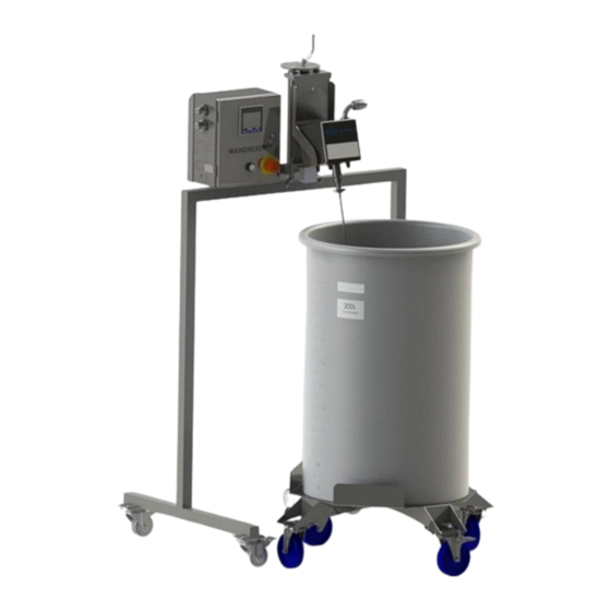
Wand Mixer Components and Accessories RDUA007BT Figure 2 Bench top Wand Mixer drive unit. The above image shows the 5 L, 10 L, and 20 L containers. Both the 5 L and 10 L containers are on stand RESA003A. RDUA008FB Figure 3 Floor based Wand Mixer drive unit. -
Page 11: Wand Mixer Toolbox
Wand Mixer Toolbox Figure 4 Toolbox and contents (215-18520-00). Wands The rotational wands provide the rotational motion of the mixing sleeve inside the biocontainer. The wand is introduced in the open end of the sleeve, while its hexagonal head is received by motor shaft adaptor. It is very important to only use each wand with its designated nominal biocontainer size. - Page 12 Operator Interface and Control The Wand Mixer is sealed for water/spray resistance. Note: The Wand Mixer is sealed for water/spray resistance. The controls are located on the face panel of the control box. They include: a touchscreen controller, quick adjustment keys, power switch, and emergency stop push button. In addition, connections for remote control are available on the left side panel of the control box as shown in Figure 6.
-
Page 13: Pre-Mixing Setup
Pre-Mixing Setup The mixing biocontainer must be assembled properly prior to mixing. The following components are needed to assemble the biocontainer: Stainless steel rotational wand. ▪ Stainless steel coupler – The coupler provides mechanical interface between the biocontainer and the ▪... -
Page 14: Mixing
Now that the biocontainer is properly assembled, the biocontainer must be connected properly to the mixer. First position the mixing biocontainer with retaining tank in such a way that the fitting with coupler is located approximately under the shaft adaptor as shown below in Step 1 of 8. Adjust the vertical position of the motor by rotating the handle of the motor positioner until the distance between the coupler and the shaft adaptor is about 50 mm or 2 inches. -
Page 15: Maintenance
D isconnecting the Biocontainer After the motor has come to a complete stop, remove the clamp connecting the coupler with shaft adaptor. Push the coupler down away from shaft adaptor by 25-50 mm or 1-2 in. Push the wand down and away from shaft adaptor until the hex head of the wand is released from adaptor. -
Page 16: Troubleshooting
10.3 Procedures 10.3.1 Power Cord Replacement Only use power cords provided by Pall. Should you need to replace the power cord with an alternative one with a different type of plug, follow the procedure as described below. Changing the power cord is performed through a power entry connector on the back panel of the control box. -
Page 17: Sd Micro Card Replacement
Figure 9 Power cord replacement. 10.3.2 SD Micro Card Replacement Micro SD cards are compatible with the memory slot. The PLC uses a FAT 32 file system format. The memory slot is equipped with a “push-in, push-out” connector for Micro SD cards insertion. To change the SD card: Switch the unit off and unplug it from the external power source. -
Page 18: Speed Calibration Verification
10.3.3 Speed Calibration Verification Manual mode of operation must be set. Equipment recommended: Reflective tape attached to the mixer head. ▪ Optical Tachometer: Omega HHT13 or equivalent ▪ Set the permanent run speed of rotation to 20 RPM. Press and hold the “Start” button, rotation started. Wait until the mix head accelerates to its nominal speed of rotation. -
Page 19: Cleaning And Decontamination Guide
Table 9 Rotational speed calibration test measurements. External Panel Tachometer Tachometer External Maximum Maximum Panel Tachometer Deviation Falls Deviation Falls External Panel Reading Reading Within Within Set Point Tachometer Allowable Tachometer Allowable Allowable Allowable (RPM) Reading (RPM) Range (RPM) Reading (RPM) Range (RPM) Range (Y/N) Range (Y/N) -
Page 20: Operator Control Interface
Operator Control Interface 12.1 Navigating the Wand Mixer Control Screen Each screen in the Wand Mixer control software has several common elements. The window bar shows the name and/or status of each screen. To return to the previous screen, press the back button in the upper right corner of the screen. -
Page 21: Maintenance
12.1.5 Maintenance This includes all supervisor functions, plus full access to system and program parameters and functions. Press P W on the top left corner of the screen Select the access level from the U se r Login screen Figure11 then choose P assword Figure 12 to open the password entry screen. -
Page 22: Operating The Wand Mixer
Operating the Wand Mixer To select the mixer’s operation mode, press one of the buttons on the Main Menu. The three mode screens—the Automatic Mode screen, the Manual Mode screen, and the Remote Mode screen— are the locations for setting mixing parameters. Figure 15 Main Menu screen. -
Page 23: Loading A Recipe
13.2 Loading a Recipe To load a recipe, follow these steps: On the Automatic Mode scene, press Select. The Recipe Selector screen will open. Use the buttons on the Recipe Selector screen to load recipes and view their contents. At the top of the screen, press the arrow buttons to move through the list of recipes. In the lower right corner of the screen, press the Back and Ne x t buttons to move through the individual instructions in the selected recipe. - Page 24 Press P ause to set the length of time the Wand Mixer should pause for that instruction. When the keypad opens, type the length of time to pause and then press Ente r. Press Run to set the length of time the Wand Mixer should run for that instruction. When the keypad opens, type the length of time to run the mixer and then press Ente r.
-
Page 25: Setting Up A Manual Job
Figure 19 Figure 20 Manual mode parameters screen. Manual mode permanent screen 13.7 Setting Up a Manual Job Parameters available for a manual job are speed of rotation of the wand (RPM) and duration of run (hh:mm). Previous settings are remembered until they are changed manually. Quick adjustment of manual job parameters is possible from the PLC face panel with dedicated keys regardless of run status. -
Page 26: Starting A Manual Job
13.8 Starting a Manual Job To a manual job press and hold the S tart button on the Manual Mode screen. The mixer will start, and the current status will show in areas with dark backgrounds: the remaining time (for timed jobs) or the “Permanent Run” (for continuous runs) and net mixing time. - Page 27 To use the remote mode: Press Remote Mode on the Main Menu. The Remote Mode screen opens in “Local Control” status indicated in status bar. To switch control to any remote equipment connected to the mixer, first make sure that the equipment is correctly connected to the Wand Mixer and powered up.
-
Page 28: Failure Detection
Failure Detection If failure happens while any of Editor screen is opened the alarm is generated but notification will not appear on screen until escape from Editor to any of Mode screens. Failure detected by the system will activate Failure mode while in any mode of operation. Failure mode causes the motor rotation to stop, displays an alarm notification to the operator and generates an alarm output signal for remote control. -
Page 29: Types Of Failure
14.1 Types of Failure The three below failures can stop the current job. 14.1.1 Manual E-Stop When an operator presses the E-Stop button on the Wand Mixer, the motor rotation immediately stops, and the ALARM appears on the screen. To reset the unit, follow the following steps: Release the E-stop button by pulling it until it clicks. - Page 30 Figure 26 Figure 27 Supervisor Main Menu screen Supervisor Settings screen Supervisor settings editor allows: Select the date format for indication on screens: mm:dd:yy or dd:mm:yy Login to system as Supervisor ▪ Press the setup button on the Main Menu screen ▪...
- Page 31 Enter the new password twice as prompted and press C hange ▪ Press to return to the Settings list ▪ Adjust auto logout time Login to the system as Supervisor ▪ Press the setup button on the Main Menu screen ▪...
- Page 32 Figure 28 Figure 29 Import/Export screen. Confirmation screen. Import of recipe library from memory card Insert a SD card into the Memory slot ▪ Login to the system as Supervisor ▪ Press the setup button on the Main Menu screen ▪...
-
Page 33: Finishing Mixing Run
14.2 Finishing Mixing Run Each time upon finishing run the notification to operator is exposed on screen. Details of the notification depend on events during process. Possible scenarios are provided in the table below. Table 10 Finish notification details. Process Condition Finish Notice Content Started During Run... -
Page 34: Spare P Arts And Accessories
Sp are Parts and Accessories Table 12 Standard accessories. Part Number Description 4100048 Bushing, wand HDPE (Included in tool box) 201487 Quickclamp tube fitting wingnut clamp (included in tool box) 4100049 Coupler, wand, stainless steel (included in tool box) 4100153NS Plate, clip for 1 in. -
Page 35: Electrical Schematic
Electrical Schematic Figure 30 Electrical schematic. -
Page 36: Service
Should your Wand Mixer require service, contact the Equipment Support Hotline. Americas: ▪ Phone: 1-855-920-PALL (7255) Hours of Operation: 8AM – 8PM EST, Monday – Friday EMEA: ▪ Phone: 00800 PALL TECH (7255 8324) Hours of Operation: 8AM – 5PM CET, Monday – Friday Patents: ▪ Pall.com/patents Website: ▪... - Page 37 Portsmouth PO6 4BQ Visit us on the web at www.pall.com _______________________________________________________________ © Copyright 2021, Pall Corporation. Pall and are trademarks of Pall Corporation. ® indicates a trademark registered in the USA. Filtration.Separation.Solution is a service mark of Pall Corporation. Public...
- Page 38 Report. This authorization also applies to multiple listee model(s) identified on the correlation page of the Listing Report. This document is the property of Intertek Testing Services and is not transferable. The certification mark(s) may be applied only at the location of the Party Authorized To Apply Mark. Pall Corporation Multisource Manufacturing LLC Applicant: Manufacturer: 25 Harbor Park Dr.
- Page 39 Visit us on the Web at www.pall.com/biotech Contact us at www.pall.com/contact Corporate Headquarters Pall Corporation has offices and plants throughout the world. To locate the Pall office or distributor nearest you, visit www.pall.com/contact. Port Washington, NY, USA +1-800-717-7255 toll free (USA) The information provided in this literature was reviewed for accuracy at the time of publication.
Need help?
Do you have a question about the Biotech RDUA007BT and is the answer not in the manual?
Questions and answers