Advertisement
Table of Contents
- 1 Table of Contents
- 2 Specifications & Electrical Schematic
- 3 Introduction
- 4 Principle of Operation
- 5 Wandmixer System Components
- 6 Frame and Drive Motor
- 7 Assembly Prior to Mixing
- 8 Drive Motor Operation
- 9 Disconnecting Bag from Motor
- 10 Service
- 11 Spare Parts
- 12 Declaration of CE Conformity
- Download this manual
Page #: 1 of 20
Document #: 5100000
Revision: C
USD 3187
WandMixer
®
Single-Use Mixing System
OPERATOR MANUAL
BENCH-TOP SYSTEM
RDUA003A, RDUA005A, RDUA005B, RDUA005C
Pall Life Sciences. USA: Port Washington, NY, USA 1 800 717 7255 toll free (USA),+1 516 484 5400 phone,
biopharm@pall.com e-mail, www.pall.com. Europe: Fribourg, Switzerland +41 (0)26 350 53 00 phone,
LifeSciences.EU@pall.com e-mail. Asia-Pacific : +65 6389 6500 phone, sgcustomerservice@pall.com e-mail
© 2012, Pall Corporation. Pall, Allegro, Kleenpak, Stax and the Allegro Design are trademarks of Pall Corporation. ®
indicates a trademark registered in the USA and TM indicates a common law trademark.
Filtration.Separation.Solution is a service mark of Pall Corporation.
Advertisement
Table of Contents

Subscribe to Our Youtube Channel
Related Manuals for Pall WandMixer RDUA003A


Summary of Contents for Pall WandMixer RDUA003A
- Page 1 BENCH-TOP SYSTEM RDUA003A, RDUA005A, RDUA005B, RDUA005C Pall Life Sciences. USA: Port Washington, NY, USA 1 800 717 7255 toll free (USA),+1 516 484 5400 phone, biopharm@pall.com e-mail, www.pall.com. Europe: Fribourg, Switzerland +41 (0)26 350 53 00 phone, LifeSciences.EU@pall.com e-mail. Asia-Pacific : +65 6389 6500 phone, sgcustomerservice@pall.com e-mail ©...
- Page 2 ® 9. Use only Pall Rotational Wands and Pall heavy duty frames. Use of non-Pall rotational wands or frames could result in injury to the operator or damage to the mixing system. DO NOT submerge drive unit in water...
- Page 3 Page #: 3 of 20 Document #: 5100000 Revision: C EXPLANATION OF SYMBOLS WEEE: Waste of Electrical and Electronic Equipment HIGH VOLTAGE CAUTION PROTECTIVE EARTH: Ground MAIN POWER SWITCH CE CERTIFIED...
-
Page 4: Table Of Contents
Page #: 4 of 20 Document #: 5100000 Revision: C TABLE OF CONTENTS Section Page #(s) Table of contents Specifications & Electrical Schematic Introduction Principle of Operation WandMixer System Components 8-12 Frame and Drive Motor Assembly Prior to Mixing 13-15 Drive motor operation Disconnecting Bag from Motor Service... -
Page 5: Specifications & Electrical Schematic
Page #: 5 of 20 Document #: 5100000 Revision: C 1. SPECIFICATIONS Power: 2.0/1.0 A Single Phase 115/230 VAC 50/60 Hz, full load current Input Wattage: Less than 180 Watts at maximum speed Speed Range 0-350 RPM Degree of Protection: NEMA 4X, IP 65 Altitude Up to 1000 m (3280 ft.) -
Page 6: Introduction
Page #: 6 of 20 Document #: 5100000 Revision: C Electrical Schematic, 230 VAC: 2. INTRODUCTION ® The WandMixer System is a revolutionary mixer that provides efficient mixing utilizing a ® patented rotational wand technology in a sterile closed bag. The WandMixer System is able to mix in sterile disposable hermetically sealed bags ranging in volume from 5L to 50L. -
Page 7: Principle Of Operation
Revision: C 3. PRINCIPLE OF OPERATION ® Pall rotational wand mixing technology provides non-invasive mixing inside sterile plastic bags. It is based on rotating of the curved rod pre-introduced in the sleeve of the mixing bag. The rod is separated from the processed sterile fluid by sleeve which is hermetically sealed on one end. -
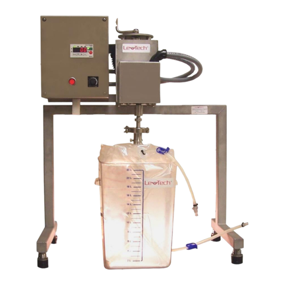
Page 8: Wandmixer System Components
Page #: 8 of 20 Document #: 5100000 Revision: C ® 4. WandMixer SYSTEM COMPONENTS Control Box Motor Positioner Drive Motor Frame Coupling System Tank with Mixing Bag ® Figure 2: Main components of WandMixer disposable mixing system (shown with 20L tank) - Page 9 Page #: 9 of 20 Document #: 5100000 Revision: C 4.1 Coupler Stainless steel coupler provides mechanical interface between the bag and the driving motor. It has hollow bore that receives the wand fitting on the bag. The coupler is secured on the sleeve fitting of the bag with two thumb screws.
- Page 10 Page #: 10 of 20 Document #: 5100000 Revision: C 4.2 Rotational wand Rotational wand provides the rotational motion of the mixing sleeve in inside the bag. The wand is introduced in the open end of the sleeve, while its hexagonal head is received by motor shaft adaptor.
- Page 11 Page #: 11 of 20 Document #: 5100000 Revision: C Figure 6: Assembly of Rotational wand with Wand Bushing 4.4 Shaft adaptor The shaft adaptor interfaces between the coupler and the driving motor. Adaptor receives the hexagonal head of rotational wand. The bearing in the flange of the shaft adaptor decouples the rotation of the shaft from the bag.
- Page 12 Page #: 12 of 20 Document #: 5100000 Revision: C 4.5 Clamp The clamp secures the connection between the mating flanges of coupler and shaft adaptor. Figure 8: Stainless steel clamp open (left) closed (right)
-
Page 13: Frame And Drive Motor
Page #: 13 of 20 Document #: 5100000 Revision: C 5. FRAME AND DRIVE MOTOR The frame of the mixing system houses the driving motor, motor positioner and control box, see Figure 2 (page 8). Motor positioner allows an adjustment of the vertical position of the motor by rotating the handle on the top of the positioner. - Page 14 Page #: 14 of 20 Document #: 5100000 Revision: C Figure 9: Sequence of steps to assemble mixing bag with coupler and wand a-rotational wand, b-bushing, c-coupler...
- Page 15 Page #: 15 of 20 Document #: 5100000 Revision: C 6.5 Position the mixing bag with retaining tank in such a way that fitting with coupler is located approximately under the shaft adaptor (see Figure 10, below). 6.6 Adjust vertical position of the motor by rotating the handle of the motor positioner until the distance between the coupler and the shaft adaptor is about 2 inches.
-
Page 16: Drive Motor Operation
Page #: 16 of 20 Document #: 5100000 Revision: C 7. OPERATING DRIVE MOTOR 7.1 Plug the power cord in to the proper power source identified on the nameplate of the system. 7.2 Depress the round button of the main switch to energize the system (the button will illuminate). -
Page 17: Disconnecting Bag From Motor
Page #: 17 of 20 Document #: 5100000 Revision: C 8. DISCONNECTING BAG FROM MOTOR 8.1 Stop the motor by pressing STOP (red) button on speed display. Turn speed control potentiometer to ZERO position by turning its knob all the way counterclockwise. 8.2 Press and release the main switch button on the control box. -
Page 18: Service
Only use the WandMixer for these applications to ensure a long service life. Should your WandMixer require service, contact: North America: PALL Life Sciences 20 Walkup Drive Westborough, MA 01581 E-mail: PASS_Support@pall.com Europe: PALL Life Sciences Reugelstraat 2, B-3320 Hoegaarden, Belgium Phone: +32 (0) 16.76.61.59... - Page 20 Asia-Pacific : +65 6389 6500 phone, sgcustomerservice@pall.com e-mail © 2012, Pall Corporation. Pall, Allegro, Kleenpak, Stax and the Allegro Design are trademarks of Pall Corporation. ® indicates a trademark registered in the USA and TM indicates a common law trademark.
Need help?
Do you have a question about the WandMixer RDUA003A and is the answer not in the manual?
Questions and answers