
Related Manuals for Pall Allegro MMG403


Summary of Contents for Pall Allegro MMG403
- Page 1 Instructions for Use USD3294 Allegro Magnetic Mixer Drive Unit MMG403 Filtration. Separation. Solution.
-
Page 2: Table Of Contents
Table of Contents Explanation of Symbols ....................3 Safeguards & Precautions ..................... 4 Introduction ........................6 Specifications ........................ 7 Mixing System Components and Accessories ............... 8 Dolly – Tank Assembly ....................12 Allegro Mixing Biocontainer Installation ............... 14 Docking of the Drive Unit to the Tank and Biocontainer ..........17 Operator Control Interface Guide ................ -
Page 3: Explanation Of Symbols
1. Explanation of Symbols WEEE Waste of Electrical and Electronic Equipment CAUTION HIGH VOLTAGE PROTECTIVE EARTH Ground MAIN POWER SWITCH CE CERTIFIED STRONG MAGNETIC FIELD May affect pacemakers PACEMAKER OR OTHER MEDICAL DEVICE Stay 33 cm (13 in) away until consulting with a physician... -
Page 4: Safeguards & Precautions
9. For technical assistance contact the sales organization from which you purchased the product or Pall Biotech directly. 10. Each magnetic mixer biocontainer contains a magnetic impeller, which is a source of strong magnetic field within close proximity (305 mm/12 in.) of the impeller. - Page 5 DO NOT open the machine or control box while the drive unit is plugged in. DO NOT submerge the drive in water. The unit outer surfaces may be cleaned and sanitized by wiping with a mild detergent solution. DO NOT position the machine in the way that power switch on face panel is difficult to operate.
-
Page 6: Introduction
The magnetic mixer MMG403 can be linked directly to Pall technology (such as the Pall MVP single-use system or Pall SUTFF {single-use tangential flow filtration}) to allow those systems to control the mixer as part of an automated, integrated solution. -
Page 7: Specifications
4. Specifications Table 1: Specifications Footprint WxLxH: 40 x 114 x 89 cm (15.75 x 45 x 35 in.) - compact configuration 40 x 135 x 89 cm (15.75 x 53 x 35 in.) - extended configuration Control box, cart, & mixer 304 L stainless steel enclosure material: At least 1.2 μm Ra/ 47 μin Ra... -
Page 8: Mixing System Components And Accessories
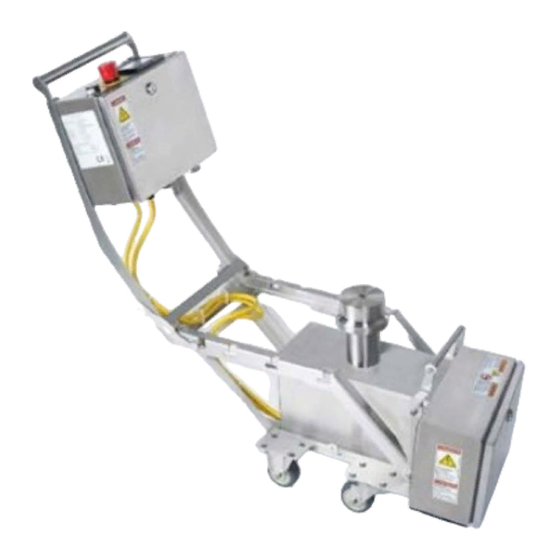
5. Mixing System Components and Accessories 5.1. Component Overview Below pictures show an overview of the key components of the Allegro magnetic mixer system. Figure 1: Magnetic mixer drive unit MMG403 with 650 L cubical tank Table 2: Overview of main components magnetic mixer system Magnetic mixer drive unit B1 Drive unit handle B2 Drive unit control box... - Page 9 Figure 2: Accessory toolbox and content Table 3: Overview of components in accessory toolbox Accessory Toolbox A1 US power cord A2 EU power cord A3 Magnetic clamp A4 Combination wrench A5 Centering aligner A6 Test impeller A7 Magnetic shield A8 Clip for 25.4 mm (1 in.) drain valve Figure 3: Round plastic tank The drive-biocontainer interface and o-ring are delivered as part of the tank (Figure 4).
- Page 10 Each mode includes a specific set of functions to support processing requirements. Additionally, there is locked mode of operation which represents variation of remote control from an external system and is intended to support control of the mixer using other equipment such as Pall MVP system.
- Page 11 After detaching the plug from the control panel, the appropriate cable and plug (for example, from the Pall MVP system) should be connected to allow for locked/remote operation. For modes of operation other than locked mode, keep the plug inserted and tightened.
-
Page 12: Dolly - Tank Assembly
5.3. Unpacking The magnetic mixer is shipped in a wooden crate with foam insets to protect the unit during transport. Make sure to store the tool box in the vicinity of the drive unit. The crate should be retained in the event that the parts have to be shipped in the future. Remove any foam and protective packaging from the drive unit before first use. - Page 13 6.2. Changing Dolly Configuration Between Center and Off-Center Impeller Port Determine which port configuration is required: central port (tanks sizes: 30 – 350 L tanks) or off-center port (500 L tanks). Each rail of the dual port has an adjuster attached to the rail with two screws.
-
Page 14: Allegro Mixing Biocontainer Installation
To set the rails for the off center port position set the right and left adjusters so that the side with words ‘OFF-CENTER’ is visible on both; see Figure 11. Ensure that the two dot marks on the right adjuster are located next to the two dot marks on the rail and single dot mark of the left adjuster is located next to the single dot mark on the left rail. - Page 15 If any such imperfections are discovered, contact Pall or the user organization’s quality group for advice on whether the Allegro mixing biocontainer should be used.
- Page 16 5. Assemble the centering aligner and magnetic clamp on the impeller on the Allegro mixing biocontainer as shown in Figure 16. Figure 15 : Assembly of Allegro mixing biocontainer with magnetic clamp/aligner assembly 6. Place the Allegro mixing biocontainer in the tank by aligning the magnetic clamp with the large port on the bottom.
-
Page 17: Docking Of The Drive Unit To The Tank And Biocontainer
8. Docking of the Drive Unit to the Tank and Biocontainer 8.1. Drive configuration The drive unit can be used in one of two configurations: standard or extended. The configurations can be switched following the procedure described in Section 11.3.1. Each configuration allows connection of the unit to different tank sizes using a universal latch as shown in Figure 18. - Page 18 Table 5: Latch positions/configuration round tanks Round Tank Latch Positions Volume Position Stamp on frame Configuration 30 L (23) 15 standard 50 L (23) 15 standard 100 L (23) 15 standard 200 L (23) 15 standard 350 L (23) 15 standard 500 L (23) 15...
- Page 19 8.2. Docking of Drive Unit to Biocontainer 1. Remove the magnetic clamp from the biocontainer container assembly before coupling. To remove the magnetic clamp, reach underneath the drive port and carefully pull the magnetic clamp downwards until it is free from the biocontainer-tank assembly. Return the magnetic clamp to the supplied accessories box for future use.
- Page 20 5. Roll the drive unit along the rails all the way until the bearings come to a stop and rest in the notch located at the end of the rails. Figure 21: Drive unit pushed until stop on tank rails 6.
-
Page 21: Operator Control Interface Guide
9. Operator Control Interface Guide 9.1. Navigating the Magnetic Mixer Control Screen Each screen in the magnetic mixer control software has a number of common elements. 1. The window bar shows the name and/or status of each screen. 2. To return to the previous screen, press the back button in the upper right corner of the screen. - Page 22 Follow these steps to enter the passcode for different user access levels and log in using that levels privileges: 1. Press PW on the top left corner of the screen 2. Select the access level from the user login screen (see Figure 24) then choose Password (see Figure 24) to open the password entry screen 3.
- Page 23 9.3. Operating the Magnetic Mixer To select the mixers’ operation mode, press one of the buttons on the main menu: Figure 25: Main menu screen Select Auto Mode for the automatic operation mode. Select Manual Mode for the manual operation mode. Select Remote Mode to control the mixer remotely.
- Page 24 9.4.1. Loading a Recipe To load a recipe, follow these steps: • On the Automatic Mode scene, press Select. The Recipe Selector screen will open (Figure 27). • Use the buttons on the Recipe Selector screen to load recipes and view their contents. •...
- Page 25 7. Press Pause to set the length of time the magnetic mixer should pause for that instruction. When the keypad opens, type the length of time to pause and then press Enter. 8. Press Run to set the length of time the magnetic mixer should run for that instruction. When the keypad opens, type the length of time to run the mixer and then press Enter.
- Page 26 Figure 28: Manual mode parameters screen (left). Manual mode permanent screen (right) 9.5.1. Setting Up a Manual Job Parameters available for a manual job are speed of rotation of impeller (RPM) and duration of run (hh:mm). Previous settings are remembered until they are changed manually. Quick adjustment of manual job parameters is possible from the PLC face panel with dedicated keys (Figure 6) regardless of run status.
- Page 27 9.5.3. Stopping a Manual Mode Job (Permanent Run) To stop a manual job that is currently running, press and hold the Stop button. When a job is stopped the screen will display ‘Successful Finish’ with a time stamp and run duration. To resume to the manual mode screen press the OK button.
- Page 28 • To switch control to any remote equipment connected to the mixer, first make sure that the equipment is correctly connected to the Magnetic Mixer and powered up. Then press and hold the switch control to remote button on the remote node screen. When the control is switched to a remote panel, the ‘remote control’...
- Page 29 Figure 31: Locked mode screen In locked mode of operation operator of remote control panel is able to: • Start/Stop the motor • Change the speed of rotation • Read the speed of rotation • Switch full control to local panel and back •...
- Page 30 At the entry point dedicated screen is exposed while all controls (local and remote) as well as motor rotation are blocked until local operator have ‘Reset to Remote’ button pressed (Figure 34). That brings system to locked mode of operation functioning according to current settings on remote panel.
- Page 31 b) Manual mode pause condition: if at the moment of alarm, the mixer is in manual mode. c) Automatic mode idle condition: if at the moment of alarm, the mixer is idled in automatic mode. d) Recipe run pause condition: if at the moment of alarm, the mixer is in automatic mode. e) Locked mode or local main menu screen (depending on settings on remote panel): if at the moment of alarm generating the mixer is in locked mode.
- Page 32 9.9. Auxiliary Functions System functionality is controlled with parameters accessible through the setup editor which is available through the main menu screen. A setup button will appear on the screen after a user has logged in at the supervisor or maintenance level (Figure 36 left). The selection of parameters available for adjustment depends on the level of access and is listed in the settings editor for the supervisor level (Figure 36 right), which opens after pressing setup set up.
- Page 33 4. Adjust auto logout time • Login to the system as supervisor • Press the setup button on the main menu screen • Select the ‘auto logout’ function using the up and down arrows • Press the curved arrow to go to the entry screen •...
- Page 34 7. Import of recipe library from memory card • Insert a micro SD card into the memory slot (See section 0) • Login to the system as supervisor • Press the setup button on the main menu screen • Select the ‘recipe imp/exp’ function using the up and down arrows •...
-
Page 35: Disconnecting Drive Unit From Tank
Disconnecting Drive Unit from Tank 1. When mixing is complete, press and hold the STOP button until top bar of the window filled (2-3 sec); unless the run finished and rotation stopped automatically. 2. Firmly hold the drive unit handle and raise the drive unit slightly to release the latch. Release the latch by pulling it toward the control box. -
Page 36: Maintenance And Care
Under the Waste Electrical and Electronic Equipment (WEEE) directive and implementing regulations, when customers buy new electrical and electronic equipment from Pall they are entitled to: • Send old items put on the market in Europe before August 13th 2005... - Page 37 11.1. Preventive Maintenance Periodical maintenance is recommended to keep the drive unit in reliable working condition. Wearing of moving parts can be monitored through the elapsed run time counter in the PLC. Run time information is accessible for viewing on the touch screen through the setup menu. Recommended preventive maintenance procedures are listed in Table 8.
- Page 38 11.3. Procedures 11.3.1. Change the Frame Configuration To change frame configuration, follow steps below and Figure 38 and Figure 39. 1. Release cables from the two cable clips on the angled cross bar on the frame. 2. At the four frame connection points loosen and remove the two nuts on the side connections and the two nuts on the top connections.
- Page 39 Figure 38: Left: Standard configuration. Right: Extended configuration...
- Page 40 Should you need to replace the power cord with an alternative one, follow the procedure as described below. Only use power cords provided by Pall for replacement. Changing the power cord is performed through a power entry connector on the back panel of the control box.
- Page 41 11.3.3. SD Micro Card Replacement: Micro SD cards are compatible with the memory slot. The PLC uses a FAT 32 file system format. The memory slot is equipped with a ‘push-in, push-out’ connector for Micro SD cards insertion. To change the SD card: •...
- Page 42 Figure 41: Fuse replacement 11.3.5. LED Bulb Replacement To change the LED bulb (see Figure 43 & Figure 44): • Switch the unit off and unplug it from the external power source • Unlock control box by rotating the latch counterclockwise using a flat-head screwdriver •...
- Page 43 Lever Figure 43: LED bulb replacement 11.3.6. Air Filter Inspection To inspect air filter, follow steps below: • Switch the unit off and unplug it from the external power source. • Lean the entire unit back to expose the bottom of the unit. •...
- Page 44 11.3.7. Cleaning and Decontamination The steel frame of the machine consists of 304 stainless steel and may be cleaned with water and isopropyl alcohol. NOTE: It is important to ensure the system is turned off before cleaning the device. 11.3.8. Speed Calibration Verification Equipment recommended: •...
-
Page 45: Spare Parts And Standard Accessories
Spare Parts and Standard Accessories Table 11 shows a list of recommended accessories and spare parts with their respective part numbers. For reference see also Figure 48 & Figure 47. Table 11: Spare parts and accessories Item Description Part Number Accessories Included in Toolbox US power cord LT-SVSP365... -
Page 46: Service
Scientific and Laboratory Services Pall operates a technical service to assist in the application of all of its products. This service is readily available to you and we welcome your questions so that we can help. In addition, a full... -
Page 47: Electrical Diagram
Electrical Diagram Figure 48: Electrical diagram control box... - Page 48 Figure 49: Electrical diagram drive box...
- Page 49 Table 12: Remote Control I/O Chart Analog I/O Connector Circuits Pin # Circuit Description Range Calibration 2, 3 Speed output 4-20 mA 0-300 RPM 4mA=0% of range 20mA=100% of range 4, 5 Speed set point input 0-300 RPM 0V=0% of range 10V= 100% of range 0-10VDC Discrete I/O Connector Circuits...
-
Page 50: Ce Certificate
CE Certificate... -
Page 51: Warranty
Pall liability under any warranty is limited solely to replacing, or issuing credit for the Allegro systems that may become defective... - Page 52 Malaysia, Mexico, the Netherlands, New Zealand, Norway, Poland, Puerto Rico, Russia, Singapore, South Africa, Spain, Sweden, Switzerland, Taiwan, Thailand, the United Kingdom, the United States, and European Headquarters Venezuela. Distributors in all major industrial areas of the world. To locate the Pall office or distributor nearest you, visit www.pall.com/contact. Fribourg. Switzerland The information provided in this literature was reviewed for accuracy at the time of publication.
Need help?
Do you have a question about the Allegro MMG403 and is the answer not in the manual?
Questions and answers