
Related Manuals for VARISCO J


Summary of Contents for VARISCO J
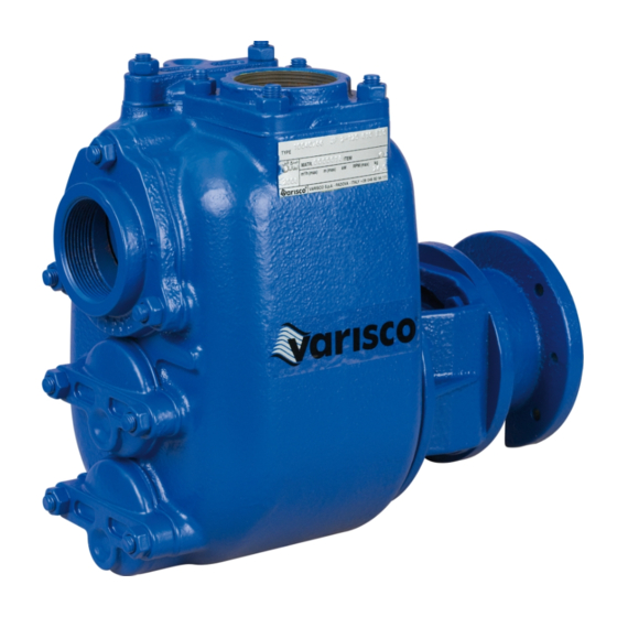
- Page 1 Instructions for the installation, use and maintenance of self-priming centrifugal pumps...
- Page 2 Before starting the pump read this instruction manual carefully The pump has been thoroughly tested for several hours before delivery and the performance has been checked and certified within acceptable limits. If the instructions for use and maintenance are observed, the pump will give full performance for a long time.
- Page 3 CONTENTS 1 IDENTIFICATION Pag. 4 ................................. Manufacturer .
-
Page 4: Warranty
The pumps are suitable for handling liquids of viscosity up to 50 cSt containing solids in suspension. They are used in industry, civil engineering, shipbuilding, waste water treatment, construction and agriculture. 1.8 In case of breakdown Contact the nearest Varisco distributor (see list on pages 5, 6) or the Varisco factory: Phone: + 39 049 82 94 312 Fax:... -
Page 5: Installation
SAFETY AND ACCIDENT PREVENTION INFORMATION fig. 1 When working near the pump, dress appropriately, avoiding clothes with loose items (ties, scarves, etc.) which could get caught in moving parts. Use overalls made according to safety regulations, gloves, insulating shoes, safety glasses, ear plugs and helmet (fig.1). Do not carry out maintenance on the engine while it is running. -
Page 6: Electrical Connections
The suction line must have a diameter equal to that of the pump suction port (for diameters greater than that of the pump port, consult Varisco). If possible, avoid curves, elbows and constrictions which can limit the flow of liquid to the pump. Do not install a foot valve: the pump has a non return valve (14) incorporated in the suction port (fig. -
Page 7: Maintenance
12.1.3 Pumps with type TCW - TC8W mechanical seals Type TCW, TC8W mechanical seals are flushed according to API 610 Plan 52-53 (see diagram in fig. 8). Plan 52 has a non-pressurised tank. Plan 53 has a pressurised tank with a pressure from 1 to 2 bar higher than the pump operating pressure. - Page 8 13.2 Replacing the impeller (03) (fig. 10) - Drain the pump casing as described in paragraph 8. Attention: residual liquid may be found inside the pump casing, head and suction line; take all necessary precautions if the liquid is hazardous (inflammable, corrosive, poisonous, infected, etc.) - Unscrew the nuts (52) and remove the pump casing, taking care not to damage the casing gasket (43) - Block the impeller and unscrew the self-locking impeller nut (33) - Remove the impeller and replace it with a new one...
- Page 9 13.6 Replacing type TCW, TC8W cartridge seals (fig. 10, 13, 14, 15, 16) - Empty the pump casing as described in paragraph 8. flushing hole Attention: residual liquid may be found inside the pump casing, head and suction line; take all necessary precautions if the liquid is hazardous (inflammable, corrosive, poisonous, infected, etc.)
- Page 10 - Move the pump towards the motor and fit the indentation of the half coupling to that of the rubber collar Half coupling - Close the coupling leaving an axial play of 2 mm max. for type J couplings and 3 mm Rubber collar max. for type S couplings...
- Page 11 11 The suction or discharge lines are obstructed or clogged locate the obstructed or clogged area and clean 14.2 The pump does not deliver liquid 12 The pump is not primed see the points listed under 15.1 13 The head required by the system is greater than the rated head of the pump revise the system design or re-select the pump 14 Excessive friction losses in the suction line revise the distribution of elbows, valves, restrictions etc.;...
- Page 12 38 Flushed seal before starting up the pump, connect the flushing hole in the seal area to the flushing liquid line with a pressure of at least 2 bar. Ensure before starting the pump and during operation that there is a constant flow of flushing liquid in the seal. Flushing ensures that the liquid will be diluted in the seal area to allow the seal to operate under the best possible conditions.
- Page 13 VARISCO POMPE S.r.l. Zona Industriale Nord - Terza Strada, 9 - 35129 PADOVA - Italy Tel.+39 049 82 94 312 - Fax +39 049 80 76 762 - e-mail: export@variscopompe.com Web site: www.variscopompe.com...
Need help?
Do you have a question about the J and is the answer not in the manual?
Questions and answers