VARISCO V Series Operating Manual
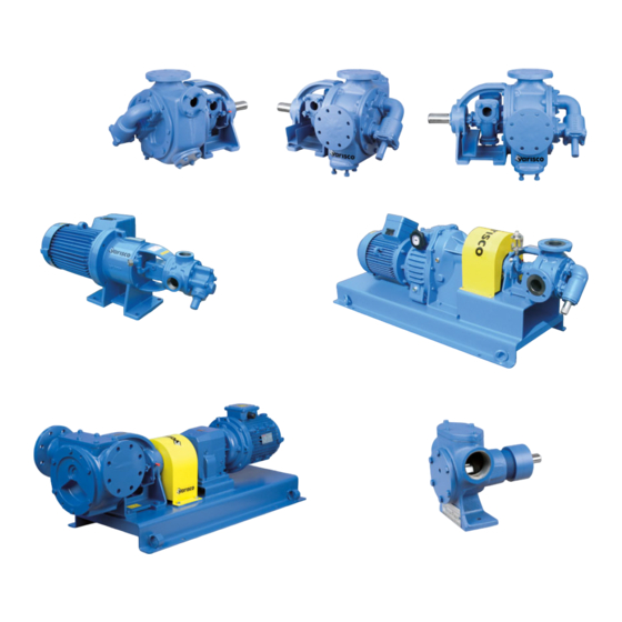
Internal gear pumps with magnetic coupling
Hide thumbs
Also See for V Series:
Table of Contents
Advertisement
Quick Links
Advertisement
Table of Contents

Related Manuals for VARISCO V Series


Summary of Contents for VARISCO V Series
- Page 1 Operating Manual V-Series Internal Gear Pumps with Magnetic Coupling...
-
Page 2: Declaration Of Conformity
Machinery Directive 98/37/EC, Annex II A and ATEX Equipment Directive 94/9/EC, Annex X B. We hereby declare that the pump unit of the V Series described on page 1 under "Technical Data" delivered by us is in conformity with the following directives and standards: EC Machinery Directive 98/37/EC, Annex I No. -
Page 3: Table Of Contents
Table of Contents: Page Declaration of Conformity General Safety Marking of instructions/notes in the Operating Manual Qualification and training of personnel Risks involved in non-compliance with safety instructions Safety-conscious work Safety instructions for the owner/operator Safety instructions for maintenance, inspection and installation work Conversion and production of spare parts by customer Improper modes of operation Explosion protection... - Page 4 4.2.2 Rating plate 4.2.3 Marking pursuant to EU Directive on equipment and protective systems intended for use in potentially explosive atmospheres Main components 4.3.1 Magnetic coupling 4.3.2 Bearings 4.3.3 Materials 4.3.4 Monitoring 4.3.5 Permissible forces, torques and moments on the pump branches 4.3.6 Expected noise levels Accessories...
-
Page 5: General
General This state-of-the-art Varisco pump has been manufactured with greatest care and is subject to continuous quality control. The present Operating Manual will familiarize you with the pump, its intended purpose and fields of application. This Operating Manual contains important information on the safe, proper and efficient operation of the pump. -
Page 6: Marking Of Instructions/Notes In The Operating Manual
Marking g of instruc ctions/note es in the O perating M Manual fety informa ation contain ned in this O Operating M Manual is ind dicated by t the following g symbol: eneral haza ard symbol for areas a ccording to ISO 7000 –... -
Page 7: Qualification And Training Of Personnel
It is imperative to observe important i information/ /signs direc ctly attached d to the ma achine such - Se ense of rota tion arrow - Sy ymbol for liq quid connec ctions - Ra ating plate ake sure the ey are kept clean and a are easily le... -
Page 8: Safety Instructions For Maintenance, Inspection And Installation Work
f hazardous s media (e.g g. explosive e, toxic, hot) ) leak out, th hey must be e drained of ff to preven exposure of f people or the environ nment to any y risk. Rele vant legal p provisions m must be observed. -
Page 9: 2.9.1 Filling The Unit
2.9.1 Filling the unit Normally the system of suction and discharge lines and consequently the pump’s interior that is in contact with the fluid is permanently filled with the pumped medium during pump operation to prevent any potentially explosive atmosphere and the risk of dry running. If the operator cannot meet this requirement, we recommend providing appropriate monitoring facilities. -
Page 10: Checking The Sense Of Rotation
riant 2: II 2 G G Eex c Tx II 2 2 G: Surface uni t intended f for use in an n area whe re an explo sive atmosp phere in the e form of gases or mi ists is likely y to occur in normal ope eration occa... -
Page 11: Maintenance
Safety infor rmation: The rele evant admis ssible opera ating tempe rature of the e pump is in ndicated in the data sh heet. If the p pump is opera ated at a hig gher temper rature and n no data she eet is availa ble or the p pump is use... -
Page 12: Transport, Intermediate Storage
Transpo ort, interm mediate sto rage 3.1 Transpo he pump un nit must be transported d properly b by competen nt personne el. Make sur re that the p pump r pump unit remains in a horizonta al position d during trans sport so that t it will not s... -
Page 13: Intermediate Storage/Preservation
Intermed diate stora ge/preserv vation As required, pumps sho ould be test ted and set using a liq uid that also o serves to protect the e pump’s int terior or a period of six mon nths from th he time of d delivery. -
Page 14: Description Of The Product And Accessories
Description of the product and accessories General description 4.1.1 General description of the pump V-Series internal gear pumps are volumetric rotary displacement pumps with internal gears designed to deliver fluids of any viscosity. The flow of the fluid to be delivered is produced by two gears: The directly driven rotor designed as a gear and the pinion which, also designed as a gear, engages the rotor in an off-centre configuration. -
Page 15: Operating Principle Of The Gear Pump
4.1.2 Operating principle Arranged in a pump casing a gear pump has two gears that mesh to provide its pumping action through rotation in opposite senses. The gears are mounted on two shafts which, in turn, are supported in the pump casing and the pump cover. -
Page 16: Main Components
4.2.2 Nameplate The data on the nameplate relates to a final acceptance with oil at 20° C and a viscosity of 100 cSt. 4.2.3 G C X See below Protection by constructional safety to EN 13463-5 Use in atmospheres with gas/vapour/mist Category 2 Group II As the actual maximum surface temperature varies with the temperature of the pumped fluid rather than... -
Page 17: Bearings
4.3.1.1 Internal rotor The internal rotor is mounted on the pump drive shaft. The magnets are pasted on the rotor outside and hermetically sealed in to protect them from chemical attack. 4.3.1.2 External rotor The external rotor with the coupling hub is mounted on the motor shaft. The magnets sit on its inside. The magnets actually fitted are provided as a function of the torque to be transmitted by the coupling. -
Page 18: Permissible Forces, Torques And Moments On The Pump Branches
1,040 V100- 1,300 Expec cted noise e sound pre essure level l of V-Series s Varisco pu umps with d drive, as me easured at t the pump he eight at 1 m tance from the pump, is less than n 75 dB for all models. -
Page 19: Installation
. In case of ubt or if dam mage is fou und, please contact you ur supplier of Varisco p pumps. • re must be taken to ma ake sure tha at hot air fro om other ins... -
Page 20: Foundation
Found dation e structure must be pre epared such h that the d imensions c conform to t those show wn in the dim mensional awing/instal lation drawi ing. e concrete f foundations s shall have a sufficient t concrete s trength (at least Class X0) to perm... -
Page 21: In- Und Außerbetriebnahme
To pr revent entry y of foreign matter, whi ch may res ult in destru uction of the e pump, a su uction filter with a filte er rating ne eeds to be installed o n the inlet s side. Given n its inner flo ow resistan ce, the filte... -
Page 22: Ausbau
Removing the pump If the pump is under warranty you will need to contact Varisco prior to removing the pump. Otherwise, warranty claims will be null and void. Prior to opening the pump, make sure that: it is completely depressurised;... - Page 23 Reference to standards Potential ignition source Measures considered Trouble to be Normal expected service Hot surface Make sure that the max. permitted temperature is not EN 13463-1 exceeded! Hot surface Make sure that the rotor, the pinion and the plain bearings are EN 13463-1 properly lubricated.
- Page 24 4. Increase spring pressure. Repair or renew relief valve. Pump experiences 1. Foreign matter in pumped fluid 1. Install filter; Check materials selected. faster-than-normal Contact Varisco wear 2. Correct pump alignment. 2. Operating range exceeded (excessive noise development), Misalignment Page 24 ...
- Page 25 Trouble shooting Trouble Potential Causes Drive gets hot or Incorrectly designed delivery, Check the piping is overloaded delivery pressure Contact the manufacturer Excessive viscosity High containment Contact the manufacturer shell temperature Product flow for cooling Check filter and design interrupted High casing Foreign matter in pumped fluid...
-
Page 26: Disassembly
Failure to observe these instructions and/or the warning notes may result in risks to the operator and/or serious damage to the pump or pump unit. VARISCO S.p.A.shall not be held liable for any accidents or damage caused as a result of non-observance of this manual. -
Page 27: Disassembly Of The Pump Cover
Disassembly of the pump cover (04) Remove the screws (43). Where present, use the two threaded bores to facilitate removal. When removing the cover (04) make sure that the seal (31) will not be damaged. If damaged, replace it. This also applies to all other pump seals. Pull off the pinion (03) with pressed-in plain bearing (37) from the cover (04) via the pin (06). -
Page 28: Disassembly Of The Pump Casing
Disassembly of the pump casing (01) Unscrew the screws (44) and pull-off the casing (01). Page 28 ... -
Page 29: Disassembly Of The Plug-In Unit
Disassembly of the plug-in unit Unscrew the bolts (M3.02) and (M3.03) and pull-off the complete plug-in unit from the bearing bracket (M1.01). On principle, the plug-in unit should only be separated from the external magnet (M2.02) by radial guidance (restricted guidance). Make sure that the external magnet (M2.02) and the containment shell (M2.03) do not get in contact. - Page 30 Remove the bolts (M2.05) and pull-off the containment shell (M2.03) from the intermediate flange (M3.01). As regards the containment shell (M2.03), please remember that some remainders of the pumped fluid may still be in the pump. For safety instructions, please see the relevant media data sheet. Remove nut M18 (M3.13) and washer (M3.12) from the pump shaft (M3.08).
-
Page 31: Disassembly Of The Bearing Bracket
Disassembly of the bearing bracket Remove the feather key (M1.12) from the drive shaft (M1.03). Remove the shaft sealing ring (M1.05), the slotted nut (M1.09) and the safety plate (M1.10) from the drive shaft (M1.03). Press out the external magnet (M2.02) and the drive shaft (M1.03) with magnet hub (M2.01) from the bearing bracket (M1.01) in the direction of the external magnet (M2.02). -
Page 32: Adjusting The Axial Play
Adjusting the axial play The axial play is dependent on the viscosity and can be adjusted through various thicknesses of the cover or the casing seal. Please see the table below for further information. Pump type V50-3 V25-2 Class V60-2 V85-2 V100-2 V30-2... -
Page 33: Annex
Annex Certificate of No Objection We, the undersigned, submit the following pump and pump accessories for repair I inspection: Type: ......... P l e a s e note: Specification: ....,..This certificate must be filled out and enclosed with any shipment for repair purposes to ensure proper handling of the pump. - Page 34 Page 34 ...
- Page 35 Page 35 ...
- Page 36 ______________________________________________________________________________________________ VARISCO SpA Terza Strada, 9 - Z.I. Nord - 35129 PADOVA - Italy Tel. 049 82 94 111 - Fax 049 82 94 373 www.variscospa.com Vendite Italia: Tel. 049 82 94 111 - Fax 049 82 94 373 italia@variscospa.com...
Need help?
Do you have a question about the V Series and is the answer not in the manual?
Questions and answers