
Related Manuals for QTech QSW-6900-32H Series


Summary of Contents for QTech QSW-6900-32H Series
- Page 1 INSTALLATION MANUAL QSW-6900-32H Series Switches Hardware Installation and Reference Guide QSW-6900-32H www.qtech.ru...
- Page 2 QTECH reserves all copyrights of this document. Any reproduction, excerption, backup, modification, transmission, translation or commercial use of this document or any portion of this document, in any form or by any means, without the prior written consent of QTECH is prohibited.
- Page 3 At the same time, it is assumed that the users of this switch are already familiar with the related terms and concepts of Ethernet. Obtaining Technical Assistance QTECH Website: https://www.qtech.ru Technical Support Website: https://helpdesk.qtech.ru...
-
Page 4: Product Overview
QSW-6900-32H switches are data center oriented high density 40G/100G access switches, providing 40G/100G access, low latency, and complete data center features. QSW-6900-32H switches, with up to 32 100G ports, can be used to compose a high-performance and high- reliability data center network. The QSW-6900-32H Series Switches: Model 100G 25G/10G... - Page 5 Input current range: 3.6A Frequency: 50 Hz to 60 Hz Rated current: 3.5A to 7.2A Power Less than 300 W Consumption Optical Module The supported modules update at any time, contact QTECH for details. SFP28 Port Unsupported QSFP28 Port Supported FC Port Unsupported...
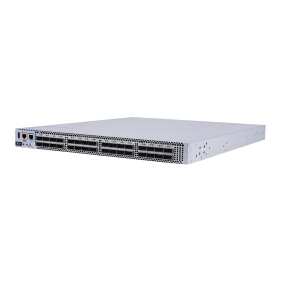
- Page 6 It is recommended users configure power supply redundancy. The heat dissipation system: Provides five fan module slots, which support 3+2 fan redundancy. It is recommended users configure all fans redundancy. Figure 1-1 Appearance of the QSW-6900-32H Front Panel Figure 1-2 Front Panel of the QSW-6900-32H www.qtech.ru...
- Page 7 The label is movable and can be withdrawn from the device. Users can mark the information such as asset name, category, code and registration date on the label which helps to improve asset management accuracy and efficiency. Figure 1-4 Asset Management Label of the QSW-6900-32H www.qtech.ru...
- Page 8 At the same time, the local USB port is compatible with most of the USB controllers except some USB flash disks. QSW-6900-32H series switches support debugging, configuration, maintenan management and host software uploading of Console ports. Console port: Use RS-232 interface electrical level and standard RJ45 connector. This interface is connected with the serial port of terminal PC to perform system debugging, configuration, maintenance, management, and host software uploading.
- Page 9 40G/100Gbps. Power Supply The QSW-6900-32H series switches support power supply the QSW-M-6900SH-PWR. The smart power supply module supports power management, and the host can read input power, input current, and temperature in real time. The power supply module supports hot swapping.
- Page 10 Error! Use the Home tab to apply Заголовок 1 to the text that you want to appear here.. Error! Use the Home tab to apply Заголовок 1 to the text that you want to appear here. The QSW-6900-32H series switches support 1+1 power supply redundancy. To improve the stability and reliability of the entire system, it is recommended to configure 1+1 power supply redundancy.
- Page 11 Leave sufficient space in the front and at the back of the chassis (at least 20 cm) for ventilation. It requires at least three fan modules to work normally. Filler panels need to be installed in the unoccupied fan module slots to ensure ventilation and heat dissipation and avoid dusts. www.qtech.ru...
-
Page 12: Preparation Before Installation
Do not place the device in a damp location. Do not let any liquid enter the chassis. Any nonstandard and inaccurate electrical operation can cause accidents such as fires or electrical attacks, thus causing severe, or even fatal damages to human bodies and the devices. www.qtech.ru... -
Page 13: Installation Site Requirements
Make sure the cabinet complies with the following conditions if the QSW-6900-32H is installed in the cabinet: Install the switch in an open cabinet as much as possible. If you install the switch inside a closed cabinet, be sure that the cabinet has a good ventilation and heat dissipation system. www.qtech.ru... - Page 14 The cabinet should be properly grounded. 2.2.2 Ventilation Requirements For the QSW-6900-32H series products, leave sufficient space in the front and at the back of the chassis (at least 20cm) for ventilation. After various cables are connected, bundle the cables or place them in the cable management bracket to avoid blocking air inlets.
- Page 15 The lightning protection system of the facility is an independent system that consists of the lightning rod, down lead conductor and the connector to the grounding system, which usually shares the power reference ground and yellow/green safety cable ground. The lightning discharge ground is for the facility only, not for the device. www.qtech.ru...
-
Page 16: Precaution For Fiber Connection
Rx end of this device to the Tx end of the peer device. 2.4 Installation Tool Common Tools Cross screwdrivers, related electric and optical cables, bolts, diagonal pliers, straps Special-purpose Tools Anti-static gloves, stripping pliers, crimping pliers, crystal head crimping pliers, wire cutters www.qtech.ru... - Page 17 Air-laid paper, fiber end microscope Tools Meter Multimeter, errormeter, optic-power meter QSW-6900-32H series is not shipped with a tool kit. You need to prepare a tool kit by yourself. 2.5 Unpacking and Checking Goods Checklist Chassis Chassis, Yellow/green grounding cables; Quick installation guide; Packing list,...
-
Page 18: Product Installation
Заголовок 1 to the text that you want to appear here. 3 PRODUCT INSTALLATION QSW-6900-32H series Ethernet switch must be used and fixed in the room. Make sure you have carefully read part 2, and be sure that the requirements set forth in part 2 have been met. -
Page 19: Cabinet Installation
Usually, you should reserve space of at least 10mm between the front panel of the equipment and that of the cabinet after www.qtech.ru... - Page 20 During the process of installation, keep the front panel of the switch forward. It is recommended use tray to install the QSW-6900-32H series switches and fix the tray on the bracket, or use the rear bracket provided with the switches.
-
Page 21: Installing And Removing A Fan Module
Place the switch on the workbench and ensure good ventilation condition around the switch. 3.5 Installing and Removing a Fan Module Wear anti-static gloves before the following operations. Installing an Fan Module Take out a new fan module from the fan module box. www.qtech.ru... - Page 22 3. Install the fan filler panel and put the removed fan module into its package Figure 3-4 Removing a Fan Module Withdraw the fan module uprightly and slowly. Install a filler panel on the location where a fan module is removed to ensure normal ventilation and dissipation and avoid dust in the chassis. www.qtech.ru...
- Page 23 2. Install a filler panel in the power module slot and put the removed power module into its package. Figure 3-6 Removing a Power Module www.qtech.ru...
- Page 24 The socket-outlet should be installed at a location near the device easy for operation. During the device installation, always make the ground connected first and disconnected last. The cross-sectional area of protective earthing conductor should be at least 2.5 mm2 (12 AWG). www.qtech.ru...
-
Page 25: Connecting The External Interface Cables
3. For the power cables, you should bind them closely along the chassis downward in a straight line wherever possible. 3.11 Installation Verification Verifying the Cabinet Verify if the external power supply matches the distribution panel of the cabinet. After equipment is installed, verify if the front/back cabinet doors can be closed. www.qtech.ru... - Page 26 AC power or lightening arrester of Ethernet port. Verifying the Power Supply Verify that the power cables are in good contact and comply with the safety requirements. To avoid body injury and components damage, cut off power supply before checking the installation. www.qtech.ru...
-
Page 27: System Debugging
8, parity check none, stop bit 1, and flow control none. Details are as follows: Choose Start > Programs > Accessories > Communications > Hyperterminal. Choose Cancel. The Connection Description window appears as shown in Figure 4-2. Figure 4-2 www.qtech.ru... - Page 28 After the serial port is selected, please click OK. The Serial Port Parameter Setting window is displayed, as shown in Figure 4-4. Set the baud rate as 9600, data bit as 8, parity check as none, stop bit as 1, and flow control as none. Figure 4-4 www.qtech.ru...
-
Page 29: Power-On Startup
Checking After Power-on (Recommended) After power-on, you are recommended to perform the following checks to ensure the normal operation of follow-up configurations. Check if printed information appears on the terminal interface. Check if the device indicator is normal. www.qtech.ru... -
Page 30: Monitoring And Maintenance
The fan in the equipment responsible for heat dissipation is provided with the fault monitoring signals. When the fan fails, a corresponding alarm will occur. Replace the faulty fan with a qualified one. Tighten the captive screws of the fan module. www.qtech.ru... - Page 31 Replacing Lithium Battery The built-in lithium batteries can support the real time clock of the QSW-6900-32H series switches without external power supply. Please contact the technical support representatives of QTECH for replacing lithium batteries.
-
Page 32: Troubleshooting
Check the installation and fastening of the modules Check the indicators on the device and the modules Check the connection of the serial ports and its parameters Check the connection of the fibers or cables of various ports Contact Technical Support of QTECH for hardware problems www.qtech.ru... -
Page 33: Common Troubleshooting Procedures
[Troubleshooting] Please contact QTECH Customer Service Department for technical support. Fault 2: The AC power module does not work The indicator on the front panel of host is OFF. The Status indicator of fan module is OFF, and the fan does not work. - Page 34 [Troubleshooting] Check whether the module is inserted correctly. If the newly-inserted module still cannot be powered on even though the checking is ok, please contact QTECH Customer Service Department for technical support. Fault 7: The link cannot be set up between fiber interfaces [Fault Description] The system runs normally.
-
Page 35: Appendix A Connectors And Connection Media
Now that CAT6A unshielded wire or CAT6 wire is applied in the cabling of the equipment room. The cabling must meet TSB-155 requirements. And the recommended cabling rules are as follows: 1) Avoid mixed cabling with other cables, or use metal clapboard in the trunking to isolate different wires. www.qtech.ru... - Page 36 Output Transmit Data- Output Transmit Data+ Input Receive Data+ Output Transmit Data- Input Receive Data- 4, 5, 7, 8 Not Used Not Used Figure A-3 shows the feasible connections of the straight-through and crossover twisted pairs of the 100BASE-TX. www.qtech.ru...
- Page 37 Figure A-3 Connection of the twisted pairs of the 100BASE-TX/10BASE-T Fiber Connection For the fiber ports, select single-mode or multiple-mode fibers for connection according to the fiber module connected. The connection schematic diagram is shown in Figure A-4: Figure A-4 Schematic Diagram for Fiber Connection www.qtech.ru...
-
Page 38: Appendix B Lightning Protection
If the ALARM LED on the power arrester is Red, you should check whether it is caused by poor grounding connection or by the reversed connection of the Null and Live lines: Use the multimeter to check the polarity of the power socket for the arrester when the LED is Red, if www.qtech.ru... - Page 39 IN, while the adapter cable connected to the switch is connected to the end of OUT) and observe whether the LED on the borad is normal or not. 5. Use the nylon button to bundle the power cables. Figure B-2 Schematic Diagram for the Ethernet port Arrester Installation www.qtech.ru...
- Page 40 Incomplete arrester installation. If there is more than one port connected to the peer device on the switch, it entails installation of arresters on all connection ports for the purpose of lightning protection. www.qtech.ru...
-
Page 41: Appendix C Cabling Recommendations In Installation
Before cables are bundled, correctly mark labels and stick the labels to cables wherever appropriate. Cables should be neatly and properly bundled, and no twisting or bending is allowed, as shown in Figure C-1. Figure C-1 Bundling up cables (1) www.qtech.ru... - Page 42 After bundling up cables with buckles, you should cut off the remaining part. The cut should be smooth and trim, without sharp corners, as shown in Figure C-2. Figure C-2 Bundling up cables (2) www.qtech.ru...
- Page 43 If heat sources cannot be avoided, high-temperature cables should be used. When using screw threads to fasten cable terminals, the bolt or screw must be tightly fastened, and anti-loosening measures should be taken, as shown in Figure C-4. Figure C-4 Cable fastening www.qtech.ru...
- Page 44 Binding by using buckles should be performed according to Table C-1. Cable Bunch Diameter (mm) Binding space (mm) 80-150 10-30 150-200 200-300 No knot is allowed in cabling or bundling. www.qtech.ru...
- Page 45 Заголовок 1 to the text that you want to appear here. For wiring terminal blocks (such as air switches) of the cold pressing terminal type, the metal part of the cold pressing terminal should not be exposed outside the terminal block when assembled. www.qtech.ru...
-
Page 46: Appendix D Site Selection
Sulfur-containing materials are forbidden. Pay attention to the location of the air conditioner. Keep the air conditioner from blowing wind straight toward the device or blowing water drops from the window or air vent toward the device. www.qtech.ru...
Need help?
Do you have a question about the QSW-6900-32H Series and is the answer not in the manual?
Questions and answers