
Subscribe to Our Youtube Channel
Related Manuals for QTech QSW-4700 Series


Summary of Contents for QTech QSW-4700 Series
- Page 1 HARDWARE INSTALLATION AND REFERENCE GUIDE QSW-4700 Series Switches Hardware Installation and Reference Guide www.qtech.ru...
-
Page 2: Table Of Contents
QSW-4700 Series Switches Hardware Installation and Reference Guide Product Overview Contents 1. PRODUCT OVERVIEW 1.1. QSW-4700 Series Switches 1.2. QSW-4700-28TX 1.2.1. Specifications 1.2.2. Appearance 1.2.2.1. Front Panel 1.2.2.2. Back Panel 1.2.3. Power Supply Module 1.2.4. Cooling 1.2.5. LED 1.3. QSW-4700-52TX 1.3.1. - Page 3 QSW-4700 Series Switches Hardware Installation and Reference Guide Product Overview 1.6. QSW-4700-28F 1.6.1. Specifications 1.6.2. Appearance 1.6.2.1. Front Panel 1.6.2.2. Back Panel 1.6.3. Power Supply 1.6.4. Cooling 1.6.5. LED 1.7. QSW-4700-52F 1.7.1. Specifications 1.7.2. Appearance 1.7.2.1. Front Panel 1.7.2.2. Back Panel 1.7.3.
- Page 4 QSW-4700 Series Switches Hardware Installation and Reference Guide Product Overview 2. PREPARING FOR INSTALLATION 2.1. Safety Precautions 2.1.1. General Safety Precautions 2.1.2. Handling Safety 2.1.3. Electric Safety 2.1.4. Electrostatic Discharge Safety 2.1.5. Laser Safety 2.2. Installation Environment Requirements 2.2.1. Ventilation Requirements 2.2.2.
- Page 5 QSW-4700 Series Switches Hardware Installation and Reference Guide Product Overview 3.8. Verifying Installation 4. VERIFYING OPERATING STATUS 4.1. Setting up Configuration Environment 4.1.1. Setting up Configuration Environment 4.1.2. Connecting an Ethernet Cable 4.1.3. Setting Parameters 4.2. Powering on Switch 4.2.1. Checklist before Power-on 4.2.2.
- Page 6 QSW-4700 Series Switches Hardware Installation and Reference Guide Product Overview 7.5. Precautions for Bundling up Cables 7.6. Site Selection 8. СПИСОК ПОДДЕРЖИВАЕМОГО ФУНКЦИОНАЛА 9. ОБЩАЯ ИНФОРМАЦИЯ 9.1. Замечания и предложения 9.2. Гарантия и сервис 9.3. Техническая поддержка 9.4. Электронная версия документа...
-
Page 7: Product Overview
Product Overview 1. PRODUCT OVERVIEW QTECH QSW-4700 series switches are new generation layer 3 switches, providing high performance, consolidated security and multiple services. The switches are mainly applied to the access layer to provide line-rate switching and complete QoS policies, prioritizing some traffic over others to ensure important data transmission without lantency. -
Page 8: Qsw-4700-28Tx
QSW-4700 Series Switches Hardware Installation and Reference Guide Product Overview Note: This is a Class A product. In a domestic environment this product may cause radio interference. In this case, users are advised to take proper measures against the interference. - Page 9 QSW-4700 Series Switches Hardware Installation and Reference Guide Product Overview Model QSW-4700-28TX • Power Supply Model: QSW-M-4700-AC Module AC Input Rated Voltage Range: 100 V AC to 240 V AC Maximum Voltage Range: 90 V AC to 264 V AC...
-
Page 10: Appearance
QSW-4700 Series Switches Hardware Installation and Reference Guide Product Overview Model QSW-4700-28TX Storage 5% to 95% RH (non-condensing) Humidity Fan Speed Control Fan Fault Alarming Temperature Supported Alarming GB9254-2008CLASS A Certification Safety GB4943-2011 Regulation Compliance Dimensions (W 442 mm x 420 mm x 43.6 mm (17.40 in. x 16.54 in. x 1.72 in.) -
Page 11: Back Panel
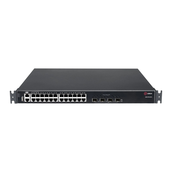
QSW-4700 Series Switches Hardware Installation and Reference Guide Product Overview System Status LED MGMT Port LED PWR1 Status LED PWR2 Status LED USB Port Console Port Management Port 10/100/1000Base-T Ethernet Port 10GE SFP+ Port 10. Port Status LED 1.2.2.2. Back Panel... -
Page 12: Led
QSW-4700 Series Switches Hardware Installation and Reference Guide Product Overview 1.2.5. LED Function Panel ID Color Status System Status LED Status System is not powered on. Blinking System is being initialized. Green (3 Continuous blinking indicates a fault. Blinking System is being located. -
Page 13: Qsw-4700-52Tx
QSW-4700 Series Switches Hardware Installation and Reference Guide Product Overview Function Panel ID Color Status 10GE SFP+ Port LED 25F to 28F No link is detected for this port. Solid The port has made a successful 1/10 Green Gbps link. - Page 14 QSW-4700 Series Switches Hardware Installation and Reference Guide Product Overview Model QSW-4700-52TX • Power Supply QSW-M-4700-AC Module AC Input Rated Voltage Range: 100 V AC to 240 V AC Maximum Voltage Range: 90 V AC to 264 V AC Frequency: 50 Hz/60 Hz Rated Current Per Circuit: 3 A •...
-
Page 15: Appearance
QSW-4700 Series Switches Hardware Installation and Reference Guide Product Overview Model QSW-4700-52TX Fan Speed Control Fan Fault Alarming Temperature Supported Alarming GB9254-2008CLASS A Certification Safety GB4943-2011 Regulation Compliance Dimensions 442 mm x 420 mm x 43.6 mm (17.40 in. x 16.54 in. x 1.72 in.) -
Page 16: Back Panel
QSW-4700 Series Switches Hardware Installation and Reference Guide Product Overview PWR1 Status LED PWR2 Status LED USB Port Console Port Management Port 10/100/1000Base-T Ethernet Port 10GE SFP+ Port 10. Port LED 1.3.2.2. Back Panel Figure 1-7 Back Panel of QSW-4700-52TX Grounding Stud Power Supply Module Slot 1 (A filler panel is required if the slot is vacant.) -
Page 17: Led
QSW-4700 Series Switches Hardware Installation and Reference Guide Product Overview 1.3.4. LED Function Panel ID Color Status System Status Status System is not powered on. Blinking System is being initialized. Green (3 Hz) Continuous blinking indicates a fault. Blinking System is being located. -
Page 18: Qsw-4700-28Tx-Poe
QSW-4700 Series Switches Hardware Installation and Reference Guide Product Overview Function Panel ID Color Status Management Port MGMT Blinking The port is sending and receiving Green traffic at 1000 Mbps. Solid Yellow The port has made a successful 10/100 Mbps link. - Page 19 QSW-4700 Series Switches Hardware Installation and Reference Guide Product Overview Model QSW-4700-28TX-POE • SFP Module SFP+ Port: Type • SFP Modules and SFP BIDI Modules • SFP+ Modules, SFP+ Cables and SFP+ BIDI Modules. • See Chapter 7 for details.
- Page 20 QSW-4700 Series Switches Hardware Installation and Reference Guide Product Overview Model QSW-4700-28TX-POE • All RJ45 ports are PoE+ capable and each port provides up to 30 W of power. The maximum power depends on the configured power supply. • Note: •...
-
Page 21: Appearance
QSW-4700 Series Switches Hardware Installation and Reference Guide Product Overview Model QSW-4700-28TX-POE Safety GB4943-2011 Regulation Compliance Dimensions 442 mm x 420 mm x 43.6 mm (17.40 in. x 16.54 in. x 1.72 in.) (W x D x H) Weight 4.3 kg (9.48 lbs.) 1.4.2. -
Page 22: Back Panel
QSW-4700 Series Switches Hardware Installation and Reference Guide Product Overview 11. 10GE SFP+ Port 12. Port LED 1.4.2.2. Back Panel Figure 1-11 Back Panel of QSW-4700-28TX-POE Grounding Stud Power Supply Module Slot 1 (A filler panel is required if the slot is vacant.) Power Supply Module Slot 2 (A filler panel is required if the slot is vacant.) - Page 23 QSW-4700 Series Switches Hardware Installation and Reference Guide Product Overview Function Panel ID Color Status System Status Status Blinking System is being located. Green (10 Solid Green System is operating normally. Solid Yellow The temperature at the air intake and exhaust vents exceeds the threshold.
-
Page 24: Led Mode Button
QSW-4700 Series Switches Hardware Installation and Reference Guide Product Overview Function Panel ID Color Status LED Mode Solid Green Switching status Indicator Mode Solid Yellow PoE status 10GE SFP+ Port 25F to No link is detected for this port. Solid Green The port has made a successful 1/10 Gbps link. - Page 25 QSW-4700 Series Switches Hardware Installation and Reference Guide Product Overview Model QSW-4700-52TX-POE Flash Memory 2 GB SDRAM 1 GB SFP Module • SFP+ Port: Type • SFP Modules and SFP BIDI Modules • SFP+ Modules, SFP+ Cables and SFP+ BIDI Modules.
- Page 26 QSW-4700 Series Switches Hardware Installation and Reference Guide Product Overview Model QSW-4700-52TX-POE All RJ45 ports are PoE+ capable and each port provides up to 30 W of power. Note: • The PoE+ port is compliant with both the PoE (IEEE802.3af) and PoE+ (IEEE802.3at) standards.
-
Page 27: Appearance
QSW-4700 Series Switches Hardware Installation and Reference Guide Product Overview 1.5.2. Appearance The front panel of the QSW-4700-52TX-POE switch provides 48 10/100/1000Base-T Ethernet ports (PoE+ capable), four 10GE SFP+ ports, one management port, one Console port and one USB port. The back panel has two power supply module slots. -
Page 28: Power Supply
QSW-4700 Series Switches Hardware Installation and Reference Guide Product Overview Grounding Stud Power Supply Module Slot 1 (A filler panel is required if the slot is vacant.) Power Supply Module Slot 2 (A filler panel is required if the slot is vacant.) 1.5.3. - Page 29 QSW-4700 Series Switches Hardware Installation and Reference Guide Product Overview Function Panel ID Color Status Solid Red System Status LED Status 1. The temperature at the air intake exhaust vents exceeds the threshold greatly. 2. The system is not functioning properly.
-
Page 30: Led Mode Button
QSW-4700 Series Switches Hardware Installation and Reference Guide Product Overview Function Panel ID Color Status 10/100/1000Base-T 1F to 48F No link is detected for this port. Ethernet Port LED Solid The port has made a successful Green 10/100/1000 Mbps link. - Page 31 QSW-4700 Series Switches Hardware Installation and Reference Guide Product Overview Model QSW-4700-28F Power Supply Module Slots Power Supply • QSW-M-4700-AC Module AC Input Rated Voltage Range: 100 V AC to 240 V AC Maximum Voltage Range: 90 V AC to 264 V AC...
-
Page 32: Appearance
QSW-4700 Series Switches Hardware Installation and Reference Guide Product Overview Model QSW-4700-28F Temperature Supported Alarming GB9254-2008CLASS A Certification Safety GB4943-2011 Regulation Compliance Dimensions 442 mm x 420 mm x 43.6 mm (17.40 in. x 16.54 in. x 1.72 in.) (W x D x H) Weight 4.2 kg (9.26 lbs.) -
Page 33: Back Panel
QSW-4700 Series Switches Hardware Installation and Reference Guide Product Overview GE SFP Port GE SFP Port LED 10. 10GE SFP+ Port 11. 10GE SFP+ Port LED 1.6.2.2. Back Panel Figure 1-19 Back Panel of QSW-4700-28F Grounding Stud Power Supply Module Slot 1 (A filler panel is required if the slot is vacant.) Power Supply Module Slot 2 (A filler panel is required if the slot is vacant.) -
Page 34: Led
QSW-4700 Series Switches Hardware Installation and Reference Guide Product Overview 1.6.5. LED Function Panel ID Color Status System Status Status System is not powered on. Blinking System is being initialized. Green (3 Hz) Continuous blinking indicates a fault. Blinking System is being located. -
Page 35: Qsw-4700-52F
QSW-4700 Series Switches Hardware Installation and Reference Guide Product Overview Function Panel ID Color Status Blinking The port is sending and receiving Management Port MGMT Yellow traffic at 10/100 Mbps. 10GE SFP+ Port 25F to 28F No link is detected for this port. - Page 36 QSW-4700 Series Switches Hardware Installation and Reference Guide Product Overview Model QSW-4700-52F Power Supply • QSW-M-4700-AC Module AC Input Rated Voltage Range: 100 V AC to 240 V AC Maximum Voltage Range: 90 V AC to 264 V AC Frequency: 50 Hz/60 Hz Rated Current Per Circuit: 3 A •...
-
Page 37: Appearance
QSW-4700 Series Switches Hardware Installation and Reference Guide Product Overview Model QSW-4700-52F GB9254-2008CLASS A Certification Safety GB4943-2011 Regulation Compliance Dimensions 442 mm x 420 mm x 43.6 mm (17.40 in. x 16.54 in. x 1.72 in.) (W x D x H) Weight 4.5 kg (9.92 lbs.) -
Page 38: Back Panel
QSW-4700 Series Switches Hardware Installation and Reference Guide Product Overview GE SFP Port LED 10. 10GE SFP+ Port 11. 10GE SFP+ Port LED 1.7.2.2. Back Panel Figure 1-23 Back Panel of QSW-4700-52F Grounding Stud Power Supply Module Slot 1 (A filler panel is required if the slot is vacant.) Power Supply Module Slot 2 (A filler panel is required if the slot is vacant.) -
Page 39: Led
QSW-4700 Series Switches Hardware Installation and Reference Guide Product Overview 1.7.5. LED Function Panel ID Color Status System Status Status System is not powered on. Blinking Green System is being initialized. (3 Hz) Continuous blinking indicates a fault. Blinking Green System is being located. -
Page 40: Power Supply Module
QSW-4700 Series Switches Hardware Installation and Reference Guide Product Overview Function Panel ID Color Status 10GE SFP+ Port 49F to No link is detected for this port. Solid Green The port has made a successful 1/10 Gbps link. Blinking Green The port is sending and receiving traffic at 1/10 Gbps. -
Page 41: Features
QSW-4700 Series Switches Hardware Installation and Reference Guide Product Overview Item Specification Maximum Output 12.5 A Current Maximum Output 150 W Power ≤ 3.5 mA Ground Leakage Current Dimensions (W x 196 mm x 50.5 mm x 40 mm (7.72 in. x 1.99 in. x 1.57 in.) -
Page 42: Led
QSW-4700 Series Switches Hardware Installation and Reference Guide Product Overview 1.8.1.3. LED Function Color Status Output Status The power supply module is not outputing power properly. Solid Green The power supply module is outputing power normally. 1.8.2. QSW-M-4700-DC Module The QSW-4700-28TX, QSW-4700-52TX, QSW-4700-28F and QSW-4700-52F switches support the QSW-M-4700-DC power module. -
Page 43: Features
QSW-4700 Series Switches Hardware Installation and Reference Guide Product Overview Item Specification Weight 0.5 kg (1.10 lbs.) -10°C to 55°C (14°F to 131°F) Operating Temperature -40°C to 70°C (-40°F to 158°F) Storage Temperature Relative 5% to 95% RH (non-condensing) Operating... -
Page 44: Qsw-M-4700-Poe-Ac Module
QSW-4700 Series Switches Hardware Installation and Reference Guide Product Overview 1.8.3. QSW-M-4700-POE-AC Module The QSW-4700-28TX-POE and QSW-4700-52TX-POE switches support the QSW-M-4700- POE-AC power module. The QSW-M-4700-POE-AC is an AC module (AC/HVDC input and DC output) providing an output voltage of 56 V and an output power of up to 600 W (PoE power: 370 W). -
Page 45: Features
QSW-4700 Series Switches Hardware Installation and Reference Guide Product Overview Item Specification -40°C to +70°C (-40°F to 158°F) Storage Temperature Relative 5% to 95% RH (non-condensing) Operating Humidity Relative Storage 5% to 95% RH (non-condensing) Humidity Operating Height 0 to 5000 m (3.11 miles) above the sea level 1.8.3.2. -
Page 46: Qsw-M-4700-Poe-Dc Module
QSW-4700 Series Switches Hardware Installation and Reference Guide Product Overview 1.8.4. QSW-M-4700-POE-DC Module The QSW-4700-28TX-POE and QSW-4700-52TX-POE switches support the QSW-M-4700- POE-DC power module. The QSW-M-4700-POE-DC module is a DC module (DC input and DC output) providing an output voltage of 56 V and an output power of up to 600 W (PoE power: 370 Note: •... -
Page 47: Features
QSW-4700 Series Switches Hardware Installation and Reference Guide Product Overview Item Specification Relative 5% to 95% RH (non-condensing) Operating Humidity Relative Storage 5% to 95% RH (non-condensing) Humidity Operating Height 0 to 5000 m (3.11 miles) above the sea level 1.8.4.2. -
Page 48: Specifications
QSW-4700 Series Switches Hardware Installation and Reference Guide Product Overview input and DC output) providing an output voltage of 56 V and an output power of up to 1000 W (PoE power: 740 W). Note: • The switch can be powered on by either one power supply module or dual power supply modules. -
Page 49: Features
QSW-4700 Series Switches Hardware Installation and Reference Guide Product Overview Item Specification -40°C to 70°C (-40°F to 158°F) Storage Temperature Relative 5% to 95% RH (non-condensing) Operating Humidity Relative Storage 5% to 95% RH (non-condensing) Humidity Operating Height 0 to 5000 m (3.11 miles) above the sea level 1.8.5.2. -
Page 50: Preparing For Installation
QSW-4700 Series Switches Hardware Installation and Reference Guide Preparing for Installation 2. PREPARING FOR INSTALLATION 2.1. Safety Precautions Note: • To avoid personal injury and device damage, carefully read the safety precautions before you install the switch. • The following safety precautions may not cover all possible dangers. -
Page 51: Electrostatic Discharge Safety
QSW-4700 Series Switches Hardware Installation and Reference Guide Preparing for Installation supply = 30/2/1.75 ≈ 8.57). In other words, the leakage protector with 30 mA rated action current supports no more than eight power supplies. In this case, the 16 power supplies in the system require at least two leakage protectors with 30 mA rated action current and each leakage protector supports eight power supplies. -
Page 52: Cleanliness Requirements
QSW-4700 Series Switches Hardware Installation and Reference Guide Preparing for Installation • In an environment with low relative humidity, static electricity is prone to occur and damage the internal circuits of the switch. • Too high temperatures can accelerate the aging of insulation materials, greatly reducing the reliability of the switch and severely affecting its service life. -
Page 53: Anti-Interference Requirements
QSW-4700 Series Switches Hardware Installation and Reference Guide Preparing for Installation 2.2.4. Anti-interference Requirements The AP is susceptible to external interference by capacitive coupling, inductive coupling, electromagnetic waves, common impedance (ground) coupling, or conduction over power lines, signal lines and output lines. Note that: •... -
Page 54: Lightning Protection Requirements
2.4. Tools Common Tools Phillips screwdriver, slotted screwdriver, related copper and fiber-optic cables, bolts, diagonal pliers, cable ties Special Tools ESD tools Meter Multimeter Note: • No tool kit is delivered with the QTECH QSW-4700 series switches. -
Page 55: Installing The Switch
QSW-4700 Series Switches Hardware Installation and Reference Guide INSTALLING THE SWITCH 3. INSTALLING THE SWITCH Note: Ensure that requirements in Chapter 2 are all met. 3.1. Installing Procedure Prepare for installation Prepare for installation Install the rack Mount the switch into the rack... -
Page 56: Before You Begin
3.3.1. Mounting the Switch in a Rack All models of the QTECH QSW-4700 series switches can be installed in a standard 19-in. four- post EIA rack. Mount the switch in the rack with the front panel face forward. -
Page 57: Mounting The Switch On The Wall
Figure 3-4 Tightening Other Screws 3.3.2. Mounting the Switch on the Wall All models of the QTECH QSW-4700 series switches can be installed on the wall. All models of the QTECH QSW-4700 series switches cannot be installed on the wall. -
Page 58: Installing The Switch On A Workbench
QSW-4700 Series Switches Hardware Installation and Reference Guide INSTALLING THE SWITCH Rotate the brackets by 90 degrees and secure the brackets to the switch by using the screws. Figure 3-5 Securing Brackets Secure the switch by using the expansion bolts. -
Page 59: Removing The Ac Power Supply Module
QSW-4700 Series Switches Hardware Installation and Reference Guide INSTALLING THE SWITCH Remove the blank filler panel in the empty slot. Keep the module nameplate face upward. Grasp the handle with one hand and place your other hand under the module to support its weight. -
Page 60: Removing The Dc Power Supply Module
QSW-4700 Series Switches Hardware Installation and Reference Guide INSTALLING THE SWITCH Connect the other end of the power cord to the DC terminal block of the rack. Connect the blue power cord to -48 V DC, and the red power cord to the -48 V GND. -
Page 61: Grounding The Switch
QSW-4700 Series Switches Hardware Installation and Reference Guide INSTALLING THE SWITCH Figure 3-11 Removing the Module Note: • Pull the module out of the slot gently. • Install the filler panel in the empty slot to allow for adequate airflow. -
Page 62: Bending Steps
QSW-4700 Series Switches Hardware Installation and Reference Guide INSTALLING THE SWITCH 3.6.1. Bending Steps Connect the RJ45 connector of an Ethernet cable to the Ethernet port on the device, and the other end to a PC. Insert the single-mode or multi-mode fiber into the corresponding interface according to the panel identification, and distinguish the transmitting and receiving ends of the fiber-optic cable. -
Page 63: Verifying Operating Status
QSW-4700 Series Switches Hardware Installation and Reference Guide Verifying Operating Status 4. VERIFYING OPERATING STATUS 4.1. Setting up Configuration Environment 4.1.1. Setting up Configuration Environment Connect the PC to the management port of the switch with an Ethernet cable. Figure 4-1 Configuring Environment 4.1.2. - Page 64 QSW-4700 Series Switches Hardware Installation and Reference Guide Verifying Operating Status Figure 4-2 In the Name box, enter the new connection name and click OK. The Connect to dialog will appear. From the Connect using drop-down list, select a COM port to be used.
-
Page 65: Powering On Switch
QSW-4700 Series Switches Hardware Installation and Reference Guide Verifying Operating Status Figure 4-4 Click OK and the HyperTerminal window will appear. 4.2. Powering on Switch 4.2.1. Checklist before Power-on • The switch is fully grounded. • The power cord is properly connected. -
Page 66: Monitoring And Maintenance
Port configuration and status • Fan and power supply status • System temperature Note: For the monitoring commands, see QTECH QSW-4700 Series Switches Configuration Guide. 5.2. Maintenance 5.2.1. Cooling System Maintenance • If the fan module fails, an alarm will be generated. •... -
Page 67: Replacing Lithium Battery
QSW-4700 Series Switches Hardware Installation and Reference Guide Monitoring and Maintenance 5.2.3. Replacing Lithium Battery The device has a built-in lithium battery to maintain the real-time clock without external power to the switch. To replace the lithium battery, contact technical support personnel. -
Page 68: Troubleshooting
QSW-4700 Series Switches Hardware Installation and Reference Guide Troubleshooting 6. TROUBLESHOOTING 6.1. Troubleshooting Flowchart 6.2. Troubleshooting 6.2.1. Fault 1: The login password is forgotten. Symptom Failed to log into the system. Suggested Action Please contact QTECH technical support. -
Page 69: Fault 2: The Ac Power Module Does Not Work
Check whether the configuration of the serial port on the HyperTerminal is consistent with that in Configuration Guide. If there is still no output on the serial port, please contact QTECH technical support. 6.2.4. Fault 4: The serial port console output is garbled. - Page 70 QSW-4700 Series Switches Hardware Installation and Reference Guide Troubleshooting Check whether the speeds of the two sides match and whether the optical fiber type meets requirements.
-
Page 71: Appendix
QSW-4700 Series Switches Hardware Installation and Reference Guide Appendix 7. APPENDIX 7.1. Connectors and Media 7.1.1. 1000BASE-T/100BASE-TX/10BASE-T The 1000BASE-T/100BASE-TX/10BASE-T is a 10/100/1000 Mbps auto-negotiation port that supports auto MDI/MDIX Crossover. Compliant with IEEE 802.3ab, 1000BASE-T requires Category 5e 100-ohm UTP or STP (STP is recommended) with a maximum distance of 100 meters (328 feet). -
Page 72: Fiber Connection
QSW-4700 Series Switches Hardware Installation and Reference Guide Appendix Figure 7-2 100BASE-TX/10BASE-T Connection 7.1.2. Fiber Connection You can choose single mode or multimode fibers according to the module types. Figure 7–3 shows connection of fiber-optic cable. Figure 7-3 Fiber-Optic Cable Connection 7.1.3. -
Page 73: Installing The Ethernet Port Arrester
QSW-4700 Series Switches Hardware Installation and Reference Guide Appendix Grounding and polarity detection indicator: If the indicator is red, cable connection is incorrect (the ground cable is not connected, or the N and L lines are reversely connected). Check your power supply line. -
Page 74: Ethernet Port Arrester
QSW-4700 Series Switches Hardware Installation and Reference Guide Appendix switch housing. The paste position for the Ethernet port arrester should be as close to the ground terminal of the switch as possible. Based on the distance between the switch ground terminal and the Ethernet port arrester, cut the ground cable for the Ethernet port arrester and firmly tighten the ground cable to the ground terminal of the switch. -
Page 75: Requirements For Cable Bend Radius
QSW-4700 Series Switches Hardware Installation and Reference Guide Appendix routed beside the rack, and top cabling or bottom cabling is adopted according to the actual situation in the equipment room, such as the positions of the DC power distribution box, AC socket, or lightning protection box. - Page 76 QSW-4700 Series Switches Hardware Installation and Reference Guide Appendix • The cable management brackets and cabling troughs inside and outside the rack should be smooth without sharp corners. • The metal hole traversed by cables should have a smooth and fully rounding surface or an insulated lining.
-
Page 77: Site Selection
QSW-4700 Series Switches Hardware Installation and Reference Guide Appendix • When screw threads are used to fasten cable terminals, the bolt or screw must be tightly fastened, and anti-loosening measures should be taken. Figure 7-9 Cable Fastening Flat washer Spring washer Flat washer •... - Page 78 QSW-4700 Series Switches Hardware Installation and Reference Guide Appendix • The equipment room should be at least 3.7 km away from the sea or salt lake. Otherwise, the equipment room must be sealed, with air conditioner installed for temperature control. Saline soil cannot be used for construction. Otherwise, you should select devices with advanced protection against severe environment.
-
Page 79: Список Поддерживаемого Функционала
QSW-4700 Series Switches Hardware Installation and Reference Guide Список поддерживаемого функционала 8. СПИСОК ПОДДЕРЖИВАЕМОГО ФУНКЦИОНАЛА Поддержка питания как AC, так и DC Наличие клемм либо сжимов(винтовых, болтовых) для подключения оборудования от сети постоянного тока DC, в соответствии с требованиями ПУЭ. -
Page 80: Общая Информация
QSW-4700 Series Switches Hardware Installation and Reference Guide Общая информация Поддержка не менее 8 очередей на каждом порту Поддержка механизма управления перегрузками WRED Поддержка алгоритма обработки очередей WRR/ DRR Поддержка алгоритма обработки очередей SP Поддержка алгоритма обработки очередей WRR+SP/DRR+SP Поддержка изоляции портов доступа в одном VLAN (исключение возможности прямого... -
Page 81: Гарантия И Сервис
Общая информация Если вы хотите написать нам по поводу данного документа, то используйте, пожалуйста, форму обратной связи на qtech.ru. 9.2. Гарантия и сервис Процедура и необходимые действия по вопросам гарантии описаны на сайте QTECH в разделе «Поддержка» −> «Гарантийное обслуживание».
Need help?
Do you have a question about the QSW-4700 Series and is the answer not in the manual?
Questions and answers