Advertisement
Quick Links
SECURITY DOOR CONTROLS ■ WWW.SDCSECURITY.COM
[t] 800.413.8783 ■ 805.494.0622 ■ E-mail: service@sdcsecurity.com ■ 801 Avenida Acaso, Camarillo, CA 93012 ■ PO Box 3670, Camarillo, CA 93011
Application
When unauthorized egress is initiated, the Exit Check
Meanwhile, the person exiting must wait allowing personnel or security respond. The door unlocks after the 15 second
delay period has elapsed, permitting egress. A signal from the fire/life safety system will release the lock immediately
for uninhibited egress in an emergency.
®
Exit Check
applications include:
Restricting the egress of patients for their own safety.
Restricting the egress of commercial center patrons for minimum security application needs.
Standard Features
Small & Compact Size
650 lbs. Holding Force
15 Second Exit Delay when activated.
1 Second Nuisance Delay
Subdued Alarm with 2 Distinct Tones:
- Alarm Activation Intermittent
- Door Release – Continuous
Choice of Activation Trigger:
- Door Movement
- Exit Device w/ REX Switch
- Touch Sense Bar w/REX Switch
Instant Reset from Bypass mode for interfacing
with Patient Monitoring Systems.
Vandal resistant Proximity Sensor Trigger
Auto Sensing 12/24VDC input power
Low Power Consumption
5 foot Power Cable
Connection for Tandem Option (Pairs of Doors)
Optional Features
30 Second Exit Delay
DPS Door Position Switch Output
BAS Bond Alert Sensor Switch Output
Tandem / Auxiliary Cable
3' Cable – 1581S-TC3
10' Cable – 1581S-TC10
P:\INST INSTRUCTIONS\DELAYED EGRESS\INST-1581S
INSTALLATION INSTRUCTIONS
®
MINI EXIT CHECK
DELAYED EGRESS EMLOCK
®
REV F2
12-22
Page 1
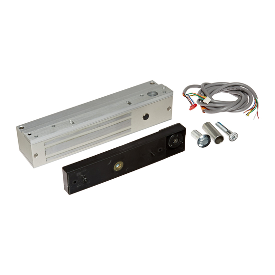
1581S
PUSH UNTIL ALARM
SOUNDS. DOOR CAN BE
OPENED IN 15 SECONDS.
KEEP PUSHING. THIS DOOR WILL OPEN
IN 15 SECONDS. ALARM WILL SOUND.
delays egress through the door for a period of 15 seconds.
Selectable Automatic & Manual Power-Up
Auto Power-Up – Occurs when power is restored and/or
the fire panel is restored (Not available on California
Versions).
Manual Power-Up – This is a UBC & California Building
Code Compliant Feature – Only after power restoration
and fire panel reset may the lock be reset manually at the
opening. A power-up reset key switch or keypad is
required adjacent to the door.
Building & Fire Life Safety Code Compliant
1581SND,NA,NH,NC
IBC International Building Code
IFC International Fire Code
NFPA 101 Life Safety Code
NFPA 1, UFC, Uniform Fire Code
UBC Uniform Building Code
CBC California Building Code
SBC Standard Building Code
1581SBD,BH,BC
BOCA National Building Code compliant
Chicago Building Code compliant
Only the 1581S and the 1581T have been UL listed as "Special Locking
Arrangements" to UL standard 294 and NFPA 101.
LISTED
USA
GWXT/GWXT7 Auxiliary Locks
FWAX Special Locking Arrangements
®
California Building
Code Compliant
LISTED
CANADA
California State
Fire Marshal Listed
CSFM #3774-0324:103
Any suggestions or comments to this instruction or
product are welcome. Please contact us through
our website or email engineer@sdcsecurity.com
Advertisement

Subscribe to Our Youtube Channel
Related Manuals for SDC 1581S


Summary of Contents for SDC 1581S
- Page 1 30 Second Exit Delay DPS Door Position Switch Output Only the 1581S and the 1581T have been UL listed as “Special Locking BAS Bond Alert Sensor Switch Output Arrangements” to UL standard 294 and NFPA 101. ...
- Page 2 Activation / Alarmed Release : Activation of the 1581S Exit Check’s 15 second unlock cycle is started by releasing the door latch and applying up to 15 lbs. of pressure to the door causing slight door movement. A short nuisance delay period is then initiated, a pre- activation warning tone is sounded .
- Page 3 ® switch for alarm reset Exit Check when and access or slight pressure is sustained bypass. applied to the bar. For doors without latching. P:\INST INSTRUCTIONS\DELAYED EGRESS\INST-1581S REV F2 12-22 Page 3...
- Page 4 TO THE FRAME OR DOOR CONFIGURATION. A FILLER PLATE OR ANGLE BRACKET MAY BE REQUIRED. SEE PAGE 5.) STEP 3. Drill and tap the two 1581S mounting holes as indicated on the paper template. PAPER TEMPLATE (NOTE: READ NOTE ON TEMPLATE WITH...
- Page 5 Figure 2C. REGULAR, FILLER PLATE & ANGLE BRACKET DETAILS ANGLE BRACKET FILLER PLATE Figure 1A Figure 1B Figure 1C REGULAR WITH FILLER PLATE WITH ANGLE BRACKET P:\INST INSTRUCTIONS\DELAYED EGRESS\INST-1581S REV F2 12-22 Page 5...
- Page 6 (CONT. BYPASS) AA GROUND TO (-) POWER – DRY CONTACT REX on blue reset wire when enabled by DIP switch M/SL INTERCONNECT CABLE INTERFACING TWO CABLE FOR TANDEM LOCK GREEN INTERCONNECT 1581S UNITS (MASTER & AUXILIARY) FOR CONNECTOR CONNECTION WHITE PAIRS OF DOORS. (CABLE MUST BE (OPTIONAL) BLACK ORDERED SEPARATELY).
- Page 7 SOUNDS. DOOR CAN BE OPENED IN 15 SECONDS. 600 Series Power Supply Patient Monitoring System Smoke Detection System Dry, Closed Contact 1581S Mini Delayed Egress Locking Magnet POWER + POWER - PSB560 Request-To-Exit Touch Sense Bar (Remote Trigger Option) LED (-)
- Page 8 8 conductors 600 Series Power Supply Patient Monitoring System Smoke Detection System Dry, Closed Contact 1581S-TC3 Tandem Cable 1581S Mini Delayed Egress 1581S Mini Delayed Egress Magnet Magnet (Set DIP switch to MASTER) (Set DIP switch to Auxiliary) POWER +...
- Page 9 STEP 5. Activation of the 1581S can be made by door movement or an external trigger. When using the door movement method, activation is achieved through the way the armature hardware is designed.
- Page 10 101-1A 728RU 101-4AM 702RU 101-PAM 101-1AK Wall Mount Reset Station or Keypad Remote Annuciators Required with 1581S Power J-Box Power Reset Reset Pair of doors with two locks and required Pair of doors with two locks and required TC-3 cable for power and Auxiliary operation...
Need help?
Do you have a question about the 1581S and is the answer not in the manual?
Questions and answers