Table of Contents
Advertisement
Quick Links
SECURITY DOOR CONTROLS ■ WWW.SDCSECURITY.COM
[t] 800.413.8783 ■ 805.494.0622 ■ E-mail: service@sdcsecurity.com ■ 801 Avenida Acaso, Camarillo, CA 93012 ■ PO Box 3670, Camarillo, CA 93011
A. Door Preparation:
1. Measure desired height from finished floor, mark a horizontal line on door and door edge.
2. Align template on edge of door with applicable horizontal at height line. Check the chart for drilling trim
holes on template and mark only holes for lock function being installed.
Height
line
3. Mortise door edge according to measurements on
installation template and drill proper holes for trim.
4. Recess for face plate, the dimension is:
L 8-1/32" x W 1-5/16" x D 7/32".
7/32"
P:\INST INSTRUCTIONS\ELECTRIFIED LOCKSETS\INST-Z7800
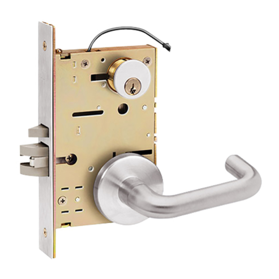
INSTALLATION INSTRUCTIONS
Z7800 SERIES
MORTISE LOCK
C L
of lever
or knob
REV F
of door edge
C
L
OPTIONAL
DOOR CORE DRILLING GUIDE
#7000-DG
02-21
Page 1
Installation
template
of cylinder
C L
of lockcase
C L
of lever or knob
C L
Vertical centerline
Any suggestions or comments to this instruction or
product are welcome. Please contact us through
our website or email engineer@sdcsecurity.com
Advertisement
Table of Contents

Related Manuals for SDC Z7800 SERIES


Summary of Contents for SDC Z7800 SERIES
- Page 1 SECURITY DOOR CONTROLS ■ WWW.SDCSECURITY.COM [t] 800.413.8783 ■ 805.494.0622 ■ E-mail: service@sdcsecurity.com ■ 801 Avenida Acaso, Camarillo, CA 93012 ■ PO Box 3670, Camarillo, CA 93011 INSTALLATION INSTRUCTIONS Z7800 SERIES MORTISE LOCK A. Door Preparation: 1. Measure desired height from finished floor, mark a horizontal line on door and door edge.
- Page 2 SECURITY DOOR CONTROLS ■ WWW.SDCSECURITY.COM [t] 800.413.8783 ■ 805.494.0622 ■ E-mail: service@sdcsecurity.com ■ 801 Avenida Acaso, Camarillo, CA 93012 ■ PO Box 3670, Camarillo, CA 93011 B. Strike Installation: Align strike template on jamb. Be sure to keep 3/8" distance between lock centerline and strike centerline.
- Page 3 SECURITY DOOR CONTROLS ■ WWW.SDCSECURITY.COM [t] 800.413.8783 ■ 805.494.0622 ■ E-mail: service@sdcsecurity.com ■ 801 Avenida Acaso, Camarillo, CA 93012 ■ PO Box 3670, Camarillo, CA 93011 C. Install Lockcase (Continued) Instructions for changing lock hand: 1. Change latchbolt handing If the hand of the latchbolt doesn’t match the door hand, remove the fixing screw and pull the latchbolt out from lock case.
- Page 4 SECURITY DOOR CONTROLS ■ WWW.SDCSECURITY.COM [t] 800.413.8783 ■ 805.494.0622 ■ E-mail: service@sdcsecurity.com ■ 801 Avenida Acaso, Camarillo, CA 93012 ■ PO Box 3670, Camarillo, CA 93011 C. Install Lockcase (Continued) 3. Connect wires as shown on the lock cover diagram (Or refer to page 6 of instructions.) 4.
- Page 5 SECURITY DOOR CONTROLS ■ WWW.SDCSECURITY.COM [t] 800.413.8783 ■ 805.494.0622 ■ E-mail: service@sdcsecurity.com ■ 801 Avenida Acaso, Camarillo, CA 93012 ■ PO Box 3670, Camarillo, CA 93011 E. Install for 07 lever trim Place the spring, collar and then reversible spring cage onto the outside lever assembly with arrows pointing in direction of lever rotation.
- Page 6 SECURITY DOOR CONTROLS ■ WWW.SDCSECURITY.COM [t] 800.413.8783 ■ 805.494.0622 ■ E-mail: service@sdcsecurity.com ■ 801 Avenida Acaso, Camarillo, CA 93012 ■ PO Box 3670, Camarillo, CA 93011 INSTALLATION WIRE DIAGRAM Model 7800 Series 12/24VDC STANDARD WIRING FROM LOCK WHT/BLK LATCHED AND SECURE ORG/BLK LOCKED STATUS...
- Page 7 [t] 800.413.8783 ■ 805.494.0622 ■ E-mail: service@sdcsecurity.com ■ 801 Avenida Acaso, Camarillo, CA 93012 ■ PO Box 3670, Camarillo, CA 93011 FAIL SAFE/FAIL SECURE CONVERSION Procedure To Change SDC Fail Safe Solenoid To Fail Secure Fail Safe Assembly Remove fail...
Need help?
Do you have a question about the Z7800 SERIES and is the answer not in the manual?
Questions and answers