Advertisement
801 Avenida Acaso, Camarillo, Ca. 93012 • (805) 494-0622 • Fax: (805) 494-8861
www.sdcsecurity.com • E-mail: service@sdcsecurity.com
REFER TO THE PROPER TEMPLATE ACCORDING TO THE TYPE OF DOOR AND FRAME APPLICATION.
READ THESE INSTRUCTIONS AND STUDY THE TEMPLATE THOROUGHLY BEFORE BEGINNING THE INSTALLATION.
IMPORTANT NOTES:
Although electromagnetic shear locks provide the utmost in aesthetics for fail-safe applications, they are less forgiving than
electric bolt locks and direct pull magnetic locks where alignment problems exist. Therefore, great care must be taken
during preparation and installation of the frame, door hardware and the shear Emlock to attain proper alignment and ensure
positive lock
operation.
Unbalanced air conditioning (stack pressure) can hinder door alignment and must be corrected to help ensure positive
locking.
HI-SHEAR EMLOCKS REQUIRE A REGULATED 12 OR 24VDC AT THE LOCK
Use only the highest quality door closer.
POSITIVE CENTERING DOOR CLOSERS ONLY should be used on double acting doors to help attain consistent dead
center alignment.
Door latching problems must be corrected prior to installation.
INSTALLATION:
1. Make sure the clearance between the door top rail and frame header is 1/8". Make adjustments to the door as required.
2. Adjust single acting door and door closer to ensure the door settles immediately and is fully closed and at rest against the
stop allowing for mutes, smoke seals or weather stripping where applicable.
Adjust double acting door and POSITIVE CENTERING DOOR CLOSER to ensure the door settles immediately and is
fully closed and at rest in the dead center of the frame.
3. Locate the vertical centerline of the Emlock and armature as close as possible to the leading door edge.
CAUTION: Wood door applications require the armature back box to be located an ample distance from the
door edge vertical grains, to avoid splitting from wood screws.
4. Determine the horizontal centerline of the door top rail thickness. The armature centerline will be the same.
Mark the door per the template.
5. Before determining the frame header centerline, single acting doors must be fully closed and at rest against the stop
allowing for mutes, smoke seals or weather stripping where applicable. Double acting doors must be fully closed and at
rest in the dead center of the frame.
6. Mark the frame header per the template.
7. Prepare the door and frame per the template.
P:\INSTALLATION INST\ELECTROMAGNETIC LOCKS\INST-SHEAR 65-66\INST-SHEAR 65-66.vsd
SECURITY DOOR CONTROLS
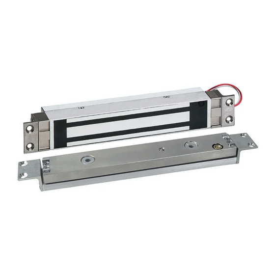
HI-SHEAR EMLOCKS
INSTALLATION INSTRUCTIONS
1565 & 1566
®
Any suggestions or comments to this instruction or
product are welcome. Please contact us through
REV F
10-12
Page 1
our website or email engineer@sdcsecurity.com
Advertisement
Table of Contents

Summary of Contents for SDC HI-SHEAR EMLOCKS 1565
- Page 1 SECURITY DOOR CONTROLS 801 Avenida Acaso, Camarillo, Ca. 93012 • (805) 494-0622 • Fax: (805) 494-8861 www.sdcsecurity.com • E-mail: service@sdcsecurity.com HI-SHEAR EMLOCKS 1565 & 1566 ® INSTALLATION INSTRUCTIONS REFER TO THE PROPER TEMPLATE ACCORDING TO THE TYPE OF DOOR AND FRAME APPLICATION. READ THESE INSTRUCTIONS AND STUDY THE TEMPLATE THOROUGHLY BEFORE BEGINNING THE INSTALLATION.
- Page 2 8. The Hi-Shear Emlock may be wire to one of two different electrical configurations. An Auto Relock time delay (standard with the 1565) is recommended for all installations to delay relocking 1 to 6 seconds after initial door closure. This will help ensure the door is fully closed and at rest to obtain alignment before the Emlock is energized. Consult Figure 7A or 7B according to material supplied.
- Page 3 ALL CENTERLINES OF THE ARMATURE MUST LINE UP LEADING EDGE WITH THE RESPECTIVE CENTERLINES OF THE MAGNET OF DOOR 13/16” FIGURE 2 3/4” 1.250" REINFORCEMENT TAB 2-13/32" 2-13/32" SDC PART #006-007-10 11.00" 12.00" 7/8" 7/16" 1-1/2” 8 HOLES 3/16" DIA 5/16” x 82° CSK 5-9/16" 5-9/16" 13/16"...
- Page 4 REINFORCEMENT TAB REVERSED 25/32" FOR HOLLOW METAL FRAME 5-1/4” 8X Ø3/16” 7/16” 10-1/2” 3/4" 5/16” x 82° CSK REINFORCEMENT TAB 13/16" SDC PART # 006-007-10 1/8" 1-5/8” for 1/8" 1-1/16” DETAIL A 1565 for 1566 16 GAUGE 1/4" to 3/4” DOOR 7/8"...
- Page 5 FIGURE 7 ACCESS DPS OPTION CONTROL = N/O Figure A GRY = COM To Fused 12V or 24V ORG = N/C red/blk DC Power Source BAS OPTION LOCK wht/blk WHT = N/O = COM RED = N/C Model 1565 – With built in Auto Relock Switch Auto Relock Delay Timer ACCESS...
- Page 6 MAINTENANCE INSTRUCTIONS The electromagnet and the armature should be handled carefully. Any damage to the surface such as paint, burrs, dirt and rust may hinder bonding of the surface and reduce holding power. IF THE SURFACE PLATING BECOMES DAMAGED Do not touch lock face with your hands. Use a soft clean dry cloth or abrasive cloth (i.e., Scotch-Brite by 3M) to clean the lock face.


Need help?
Do you have a question about the HI-SHEAR EMLOCKS 1565 and is the answer not in the manual?
Questions and answers