Table of Contents
Advertisement
Quick Links
APA9XXX
User Manual
All rights reserved. Product description and product specifications are subject to change without notice.
For latest product information, please visit Acnodes' website at www.acnodes.com.
14628 Central Ave. Chino, CA 91710
© Copyright 2020 Acnodes Corp.
7" to 32" Industrial Touch Screen Monitor
Aluminum Die-Casting Chassis
IP66 Rated Flat Front Bezel Design
Tel: 909.597.7588
Fax: 909.597.1939
Advertisement
Table of Contents

Related Manuals for Acnodes APA9 Series


Summary of Contents for Acnodes APA9 Series
- Page 1 IP66 Rated Flat Front Bezel Design User Manual All rights reserved. Product description and product specifications are subject to change without notice. For latest product information, please visit Acnodes’ website at www.acnodes.com. 14628 Central Ave. Chino, CA 91710 Tel: 909.597.7588 Fax: 909.597.1939...
-
Page 2: Revision History
Revision History Reversion Date Description 2019/01/11 Official Version 2019/06/14 Add 7”, 8”, 10.1” Models’ Data Revise Dimension Figures Revise Product Photos 2019/08/21 Revise 1.2 spec sheet 2019/09/11 Change TB-6802 Photo Revise mechanical information 2019/11/15 Add 32”... -
Page 3: Warning
Disclaimer This information in this document is subject to change without notice. In no event shall Acnodes Corporation be liable for damages of any kind, whether incidental or consequential, arising from either the use or misuse of information in this... -
Page 4: Table Of Contents
Table of Contents Revision History………………………………………………………………………………….1 Warning!……………………..………………………………………………………….……..….2 Chapter 1 Getting Started 1.1 Features…………………………………………………..……..……………………….4 1.2 Specifications……………………………………………………………….…………………4 1.3 Dimensions…………………...……………...…..……………………………..……..…9 1.4 Brief Description of APA9XXX Series .………..………………………...15 Chapter 2 AD BOARD INFORMATION 2.1 AD Board Specifications..………….…...………..….…..……………………….….28 2.2 Board Dimensions.……………………..…………….………………………..…...……29 2.3 Jumpers and Connectors Location…..…….………………………..…...……30 2.4 Jumper Settings and Connectors.…………..……………………..……...31 Chapter 3 3.1 AD Board OSD Functions………….…...………..….…..……………………….….39... -
Page 5: Getting Started
Chapter 1 Getting Started 1.1 Features Solid aluminum die-casting chassis Variety of LCD panel size selections IP66 compliant front panel VGA, DVI-D, HDMI, and DP input Wide range DC 9~36V power input High Brightness LCD and Auto Dimming for optional(Except 7”) ... - Page 6 Projected capcitive touch screen: over 90% Mechanical Construction Aluminum front bezel/Aluminum die-casting for back cover(17”/18.5”/19”) (Aluminum chassis front bezel/ steel back cover for 23.8”/32”) Mounting Panel mount / VESA mount 100 x 100 (VESA mount 200 x 100 for 23.8”) Panel Mount/VESA mount 75 x 75(7”...
- Page 7 Power Consumption and Mechanical Specification APA9070 APA9080 APA9101 Power Consumption Power Consumption MAX: 4W MAX: 6W MAX: 5.1W Mechanical Dimensions(mm) 202 x 149 x 40 231.1 x 176.1 x 50 285 x 189 x 48.9 Net Weight 1.06 Kg 1.8 Kg 1.9 Kg AP9120...
- Page 8 Standard LCD APA9070 APA9080 APA9101 7” color TFT LCD 8” color TFT LCD 10.1” color TFT LCD Display Type 800 x 600 1280 x 800 Max. Resolution 800 x 480 Max. Colors 262K 16.2M 16.7M Contrast Ratio 400: 1 500: 1 800: 1 Luminance(cd/m...
- Page 9 High Brightness LCD (Option, 32” not support) APA9070 APA9080 APA9101 7” color TFT LCD 8” color TFT LCD 10.1” color TFT LCD Display Type Max. Resolution 800 x 480 800 x 600 1280 x 800 Max. Colors 262K 16.2M 16.7M Contrast Ratio 400: 1...
-
Page 10: Dimensions
1.3 Dimensions Figure 1.1: Dimensions of APA9070 Figure 1.2: Dimensions of APA9080... - Page 11 Figure 1.3: Dimensions of APA9101 Figure 1.4: Dimensions of AP9120...
- Page 12 Figure 1.5: Dimensions of APA9150 Figure 1.6: Dimensions of APA9156...
- Page 13 Figure 1.7: Dimensions of APA9170 Figure 1.8: Dimensions of APA9185...
- Page 14 Figure 1.9: Dimensions of APA9190 Figure 1.10: Dimensions of APA9215...
- Page 15 Figure 1.11: Dimensions of APA9238 Figure 1.12: Dimensions of APA9320...
-
Page 16: Brief Description Of Apa9Xxx Series
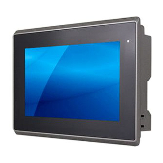
1.4 Brief Description of APA9XXX The APA9XXX is an IP66 compliant front bezel aluminum die-casting chassis display, which comes with 7”to 23.8” color TFT LCD. But for 17”/18.5”/19” and 32”, these models are Aluminum front bezel with steel chassis, with color RAL9007. The optional high brightness 1,000nits LCD is ideal for sunlight readable semi-outdoor applications. - Page 17 Figure 1.13: Front View of APA9070 Figure 1.14: Rear View of APA9070...
- Page 18 Figure 1.15: Front View of APA9080 Figure 1.16: Rear View of APA9080...
- Page 19 Figure 1.17: Front View of APA9101 Figure 1.18: Rear View of APA9101...
- Page 20 Figure 1.19: Front View of AP9120 Figure 1.20: Rear View of AP9120...
- Page 21 Figure 1.21: Front View of APA9150 Figure 1.22: Rear View of APA9150...
- Page 22 Figure 1.23: Front View of APA9156 Figure 1.24: Rear View of APA9156...
- Page 23 Figure 1.25: Front View of APA9170 Figure 1.26: Rear View of APA9170...
- Page 24 Figure 1.27: Front View of APA9185 Figure 1.28: Rear View of APA9185...
- Page 25 Figure 1.29: Front View of APA9190 Figure 1.30: Rear View of APA9190...
- Page 26 Figure 1.31: Front View of APA9215 Figure 1.32: Rear View of APA9215...
- Page 27 Figure 1.33: Front View of APA9238 Figure 1.34: Back View of APA9238...
- Page 28 Figure 1.35: Front View of APA9320 Figure 1.36: Back View of APA9320...
-
Page 29: Chapter 2 Ad Board Information
Chapter 2 AD BOARD INFORMATION 2.1 AD Board Specification Specifications 170 x 113 mm Board Size Realtek RTD2556T-CG Scalar IC 1 x HDMI Input Input 1 x DisplayPort(DP) 1 x USB2.0(Type-B) 1 x VGA 1 x Line in (3.5mm Audio Jack) Output 1 x Supports up to 24-bit LVDS FULL HD panel interface 1 x eDP... -
Page 30: Board Dimensions
2.2 Board Dimensions Figure 2.1: Dimension of TB-6802(Top) Figure 2.2: Dimension of TB-6802(Bottom) -
Page 31: Jumpers And Connectors Location
2.3 Jumpers and Connectors Location Board Top JP4/NC SPKR1/SKPL1 INVT1 External I/O HDMI CN1(DVI-D) VGA1... -
Page 32: Jumper Settings And Connectors
2.4 Jumpers Settings and Connectors 1. PW1: (5.08mm Pitch 1x3 Pin Connector),DC24V power input connector。 Pin# Power Input DC+24V Ground Model Connector Type TB-6802 2EHDVM-03P TB-6802P ELK508S-03P 2. PW2(Option): DC Jack 3. HDMI1(HDMI Input) : (HDMI Connector), High Definition Multimedia Interface connector, provide high-quality video and audio input. - Page 33 4.DP1(DisplayPort Input) : (DisplayPort Connector), DisplayPort Interface connector, provide high-quality video and audio input. Signal Name Pin# Pin# Signal Name LANE3- LANE3+ LANE2- LANE2+ LANE1- LANE1+ LANE0- LANE0+ AUX_CHP DP CAB DET AUX_CHN DP HPD RETURN DP 3.3V 5.CN1(DVI-D Input): (DVI-D Connector), Digital Visual Interface-Digital input connector.
- Page 34 CRT_BLUE Ground Ground VGA_5V DET_VGA Ground DDCA-SDA HSYNC VSYNC DDCA-SCL 8. CN3(eDP Output): (1.25mm Pitch 2x15 Connector) eDP output connector. Signal Name Pin# Pin# Signal Name LVDS_12V LVDS_12V BKLT_CTRL BKLT_EN LVDS_VCC5 LVDS_VCC5 LVDS_VCC3 LVDS_VCC3 TXA3N TXA3P VTX_TX1N VTX_TX1P TXB0N TXB0P TXB1N TXB1P DPTX_AUX_N...
- Page 35 Signal Name Pin# Pin# Signal Name LVDS_12V LVDS_12V BKLT_CTRL BKLT_EN LVDS_VCC5 LVDS_VCC5 LVDS_VCC3 LVDS_VCC3 TXA0N TXA0P TXA1N TXA1P TXA2N TXA2P TXA3N TXA3P TXACN TXACP TXB0N TXB0P TXB1N TXB1P TXB2N TXB2P TXBCN TXB3P TXB3N TXBCP LVDS_DDC_DET CPT-USB_N CPT-USB_P DDCSDA_AUTO LVDS_USB_5V DDCSCL_AUTO LVDS_VCC3 10.
- Page 36 Pin# Signal Name USB 5V USB- USB+ 12. CN7(COM Input): (2.0mm 1x4 Pin wafer connector).For external RS-232 signal input. Pin# Signal Name TXDD1 RXDD1 RTS1 13. CN8 : (2.0mm 1x3 Pin wafer connector), For external light sensor. Pin# Signal Name Sensor 14.
- Page 37 Pin# Signal Name Power Key R_LED G_LED MENU Key Down Key UP Key Select Key 16. JP2 : (2.0mm Pitch 1x3 Pin Header) JP2 Pin# Function Close 1-2 Backlight Enable & Backlight PWM Level select 3.3V Close 2-3 Backlight Enable & Backlight PWM Level select 5V 17.
- Page 38 nRST UART0_RX 19. JP8 : (2.0mm Pitch 1x3 Pin Header), JP8 Pin# Function Close 1-2 Backlight Control & Backlight PWM Level select 3.3V Close 2-3 Backlight Control & Backlight PWM Level select 5V 20. J1(VGA input): (2.0mm Pitch 1X12 Pin Wafer),Video Graphic Array Port, Provide 12Pin cable to VGA output.
- Page 39 21. J2: (2.0mm Pitch 2X3 Pin Header), RS232 or USB input for PM6000 Touch Controller Signal jumper setting. PM6000 input CN4/USB Signal output Close(3-5,4-6) ● Close(1-3,2-4) USB(CN6) Close(1-3,2-4) RS232(CN7) RS232(CN7) Close(1-3,2-4) 22. J3: (2.0mm Pitch 1X6 Pin Wafer),Touch Screen connecting Lines. Pin# 4-Wire 5-Wire...
-
Page 40: Chapter 3 Osd
Chapter 3 3.1 AD Board OSD Functions Auto Adjust Up/Left Down/Right Power Menu/Entry Power Indicator Power switch: To turn ON or OFF the power Shift the icon to the right side or shift it up Shift the icon to the left side or shift it down Menu: To enter OSD menu for related icon and item. -
Page 41: Osd Controls
When the Burn-in Mode is Unable to Eradicate… If the “RGB” is still on the top left corner of the screen, press to enter “Miscellaneous” and choose “Reset”, and then Yes, and press . When the screen goes black, disconnect power and repeat the above steps. If the “RGB”... -
Page 42: Main Menu
3.3 Main Menu In the PICTURE, there are the following items: AutoBacklight Backlight Brightness: Contrast Sharpness Exit In the DISPLAY, there are the following items: AutoAdjust H Position V Position Disp Rotate ... - Page 43 In the INPUT, there are the following items: A0:VGA D1:DP D3:HDMI Exit In the AUDIO, there are the following items: Volume Mute Audio Source Exit In the OTHER, there are the following items: ...
- Page 44 Information part.
-
Page 45: Chapter 4 Installation
Chapter 4 Installation This chapter describes how to install drivers and other software that will allow your touch screen work with different operating systems. 4.1 Windows 7 Universal Driver Installation for PenMount 6000 Series Before installing the Windows 7 driver software, you must have the Windows 7 system installed and running on your computer. - Page 46 Step 2. Read the license agreement. Click I Agree to agree the license agreement. Step 3. Choose the folder in which to install PenMount Windows Universal Driver. Click Install to start the installation.
- Page 47 Step 4. Click Yes to continue. Step 5. Click Finish to complete installation.
- Page 48 4.1.2 Installing Software (Projected Capacitive) Step 1. Click Next to continue. Step 2. Select I accept the terms of the license agreement. Click Next.
- Page 49 Step.3. Click Next to continue. Step 4. Click Install RS232 interface driver.
- Page 50 Step 5. Select None. Click Next. Step 6. Click OK. Step 7. Click Support Muti-Monitor System. Click Next.
- Page 51 Step 8. Go to C:\Program Files\eGalaxTouch. Click Next. Step 9. Click Next.
- Page 52 Step 10. Click Create a eGalaxTouch Utility shortcut on desktop. Click Next. Step 11. Wait for installation. Step 12. Click Yes to do 4 point calibration.
-
Page 53: Software Functions
4.2 Software Functions 4.2.1 Software Functions(Resistive Touch) Upon rebooting, the computer automatically finds the new 6000 controller board. The touch screen is connected but not calibrated. Follow the procedures below to carry out calibration. 1. After installation, click the PenMount Monitor icon “PM” in the menu bar. 2. - Page 54 Standard Calibration Click this button and arrows appear pointing to red squares. Use your finger or stylus to touch the red squares in sequence. After the fifth red point calibration is complete. To skip, press ‘ESC’. Advanced Calibration Advanced Calibration uses 4, 9, 16 or 25 points to effectively calibrate touch panel linearity of aged touch screens.
- Page 55 Step 2.Click “Standard Calibration” to start calibration procedure NOTE: The older the touch screen, the more Advanced Mode calibration points you need for an accurate calibration. Use a stylus during Advanced Calibration for greater accuracy. Please follow the step as below:...
- Page 56 Step 3. Select Device to calibrate, then you can start to do Advanced Calibration. NOTE: Recommend to use a stylus during Advanced Calibration for greater accuracy. Plot Calibration Data Check this function and a touch panel linearity comparison graph appears when you have finished Advanced Calibration.
- Page 57 Setting Touch Mode This mode enables and disables the mouse’s ability to drag on-screen icons – useful for configuring POS terminals. Mouse Emulation – Select this mode and the mouse functions as normal and allows dragging of icons. Click on Touch – Select this mode and mouse only provides a click function, and dragging is disables.
- Page 58 Edge Compensation You can use Edge Compensation to calibrate more subtly.
- Page 59 About This panel displays information about the PenMount controller and driver version. Multiple Monitors Multiple Monitors support from two to six touch screen displays for one system. The PenMount drivers for Windows 7 support Multiple Monitors. This function supports from two to six touch screen displays for one system. Each monitor requires its own PenMount touch screen control board, either installed inside the display or in a central unit.
- Page 60 to assign touch controllers to displays. 2. When the mapping screen message appears, click OK. 3. Touch each screen as it displays “Please touch this monitor”. Following this sequence and touching each screen is called mapping the touch screens. 4. Touching all screens completes the mapping and the desktop reappears on the monitors.
- Page 61 6. “Touch this screen to start its calibration” appears on one of the screens. Touch the screen. 7. “Touch the red square” messages appear. Touch the red squares in sequence. 8. Continue calibration for each monitor by clicking Standard Calibration and touching the red squares.
- Page 62 PenMount Monitor has the following function Control Panel Open Control Panel Windows Beep Setting Beep function for each device Right Button When you select this function, a mouse icon appears in the right-bottom of the screen. Click this icon to switch between Right and Left Button functions.
- Page 63 4.2.2 Software Functions(Projected Capacitive) General In this window, you can see there is USB Controller. Click OK to continue. Monitor Mapping to adjust touch panel to search for device...
- Page 64 Setting Beep Beep On Touch Beep On Release Beep From System Beep Beep From Sound Card Linearization Style 9 points 25 points Double Click Time Shorter Longer Double Click Area Smaller Bigger Normal mode Simulate the mouse mode...
- Page 65 Option Function Enable Constant Touch Enable Auto Right Click Enable Touch Enable Cursor Stabilization Constant Touch Area Auto Right Click Time...
- Page 66 Tools Click OK to continue the settings. 4 Points Calibration Do 4 points alignment to match display. Clear and Calibrate Clear linearization parameter and do 4 points alignment. Linearization Do 9 points linearization for better touchscreen linearity. Draw Test Do draw test to verify the touch accuracy.
- Page 67 Display In this window, it shows the mode of display. Enable Multiple Monitors. Map to main display if system has only one display monitor Full Screen Lower Screen Left Screen Upper Screen Right Screen...
- Page 68 Other Other mode of display. Quarter1~4 and Customized area. Active Area Drag active area to enable Active Area Function.
- Page 69 Hardware Saturn Hardware Configuration...
- Page 70 About To display information about eGalaxTouch and its version.
-
Page 71: Panel Mounting And Vesa Mounting
*Tighten the mounting clips to the specified torque to provide a proper seal and to prevent damage to the product. Acnodes Corporation assumes no responsibility for water or chemical damage to the product...
Need help?
Do you have a question about the APA9 Series and is the answer not in the manual?
Questions and answers