ZAPTEC Go Installation Manual
Hide thumbs
Also See for Go:
- Instruction manual (240 pages) ,
- User manual (188 pages) ,
- Quick manual (75 pages)
Table of Contents
Advertisement
Quick Links
Advertisement
Table of Contents

Summary of Contents for ZAPTEC Go
- Page 1 Zaptec Smart, small and safe Zaptec Go Installation Manual...
- Page 3 Zaptec Go works with any car No matter what you drive or where you’re going, Zaptec Go is the surest way to power your journey. Built on leading edge Norwegian green tech, we’ve created a charger, that’s as smart on the inside as it is simple...
- Page 4 This equipment must only be installed, repaired, and maintained by qualified personnel. Repairs must be carried out by Zaptec or a pre-approved workshop. All applicable local, regional, and national laws and regulations must be followed when installing, repairing, and maintaining the product.
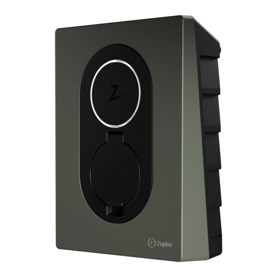
- Page 5 English Installing Zaptec Go Status light Charge card authentication (RFID) Zaptec Type 2 socket QR-code for installation and activation Scan here for the installation video...
-
Page 6: Included In The Box
English Included in the box 1 x Zaptec Go 2 x T20 4 x T20 2 x T20 3 x Cable seals 1 x Cable clamp 12-18 mm 8-14 mm cable diameter cable diameter Installation Manual User Manual... - Page 7 English 1. Remove the front cover 2. Mount the charging station Using the built-in spirit level, make sure it’s straight and at the appropriate height. Recommended height 0,9 m...
-
Page 8: Connect The Power Cable
(through the hole by the configuration switch) while pulling downwards. The Zaptec Go needs an upstream circuit breaker and dual pole RCD Type A 4. Secure cable Prevent the cable from being dislocated by using the cable clamp and screws (max torque 3 Nm). -
Page 9: Electrical Connection
English 5. Electrical connection Electrical wire dimensions 6 mm Max 12 mm Connect all wires and firmly press down all levers as illustrated. When the wires are safely attached, replace the terminal cover and turn on the circuit breaker. Ferrules are optional. Click! - Page 10 App Store (iOS) or Google Play Store (Android) and make sure the Bluetooth on your phone is switched on. When the Zaptec Go charger is switched on, Zaptec the status indicator will be orange. This means it is ready to be configured.
-
Page 11: Switch Configurations
9 - Not in use 0 - Unconfigured or configured with App To configure with the switch Zaptec recommends that you use the • Circuit breaker value and available Zaptec App to configure the charger power for charging is set to the same whenever possible. - Page 12 English 7. Confirm status indicator Configuration is complete when the circular light (status indicator) changes from green to white. 8. Mount the front cover Secure and lock the front cover (max torque 1 Nm).
- Page 13 English 9. That’s it! If you have followed all the steps so far, then the Zaptec Go should be configured and online. Make sure you hand over the User Manual to the owner of the charger. Remind the owner that they should create a Zaptec App account to activate...
- Page 14 Load Balance = max 32A in total to the chargers. NB: Equal value Circuit breaker and dual pole RCD type A. Must be equal in value on installations with several Zaptec Go. One circuit breaker and RCD type A per Zaptec Go. Integrated residual current protection...
- Page 15 Blue Charging. Charging complete or charging is waiting Green for scheduled start. Waiting for authorization Yellow via Zaptec App or RFID. Charger not configured. Orange Error detected. Unplug vehicle and restart the charging station. Updating firmware. Purple This normally takes a few minutes.
- Page 16 English 12. Support and repairs If you discover an issue, please read the Troubleshooting section before contacting Zaptec Support, or visit zaptec.com/support.
-
Page 17: Troubleshooting
Zaptec App» • Check the installation and charger power management settings in the Zaptec Portal. Read more on zendesk.zaptec.com Zaptec Charger AS collects data from the product via the network. More information on our privacy guidelines can be found at zaptec.com/privacy. -
Page 18: Storage And Maintenance
English 14. Storage and Maintenance The product must be kept in a dry room with a stable temperature. The following periodic maintenance is recommended: • Wipe down the charging station must be carried out by qualified with a damp cloth. personnel in accordance with Norwegian legislation and regulations. -
Page 19: Technical Specifications
English 15. Technical specifications Mechanical and installation UNIT PARAMETER TEST CONDITION Dimensions H: 242 W: 180 D: 75 Weight Altitude 2000 Input cable cross section Input cable diameter 18.5 Degree of protection IP54 Charging mode Mode 3, case B Mechanical strength IK08 Pollution degree Installation environment... - Page 20 English 15. Technical specifications (continued) General UNIT PARAMETER TEST CONDITION Phase-Neutral Rated voltage (Un) Phase-Phase Rated current (In) Rated frequency Standby power consumption Ambient operating temperature Maximum charging power TN 1 phase @ 32 A Protection class Overvoltage category Connectivity PROTOCOL SUPPORTED STANDARDS LTE Cat M1...
- Page 21 English Integrated RDC-DD UNIT PARAMETER SYMBOL Residual DC operating current IΔdc 0.006 Operating characteristics RDC-DD according to IEC 62955 Making and breaking capacity IΔm Residual making and breaking capacity Rated conditional short- circuit current IΔc Rated conditional residual short-circuit current Upstream circuit breaker and RCD UNIT PARAMETER...
- Page 22 English...
- Page 23 English...
- Page 24 English Zaptec Charger AS Professor Olav Hanssens vei 7A 4021 Stavanger Norway Made in Norway zaptec.com © Zaptec Charger AS 28.10.2022. All rights reserved. ZM000909...


Need help?
Do you have a question about the Go and is the answer not in the manual?
Questions and answers