Table of Contents
Advertisement
Advertisement
Table of Contents

Related Manuals for PaloAlto Networks ION 1200 Series


Summary of Contents for PaloAlto Networks ION 1200 Series
- Page 1 ION 1200 Hardware Reference docs.paloaltonetworks.com...
- Page 2 Contact Information Corporate Headquarters: Palo Alto Networks 3000 Tannery Way Santa Clara, CA 95054 www.paloaltonetworks.com/company/contact-support About the Documentation • For the most recent version of this guide or for access to related documentation, visit the Technical Documentation portal docs.paloaltonetworks.com. • To search for a specific topic, go to our search page docs.paloaltonetworks.com/search.html. •...
-
Page 3: Table Of Contents
Table of Contents Before You Begin....................5 Tamper Proof Statement......................6 Third-Party Component Support..................... 7 Product Safety Warnings......................8 ION 1200 Overview..................13 Overview ION 1200.........................14 ION 1200 Hardware Specifications..................16 ION 1200 Front Panel......................22 ION 1200-C-NA/ROW Front Panel..................24 ION 1200-C-5G-WW Front Panel..................26 ION 1200 Back Panel...................... - Page 4 Table of Contents Install Antennas in the ION 1200-S..................75 Install the ION 1200-S on a wall..................77 ION 1200-S Wall Mount Template..................80 Install the ION 1200-S on a Rack..................81 Troubleshoot ION 1200.................87 Troubleshoot Common Issues with the ION 1200............88 ION 1200 Hardware Reference 2022 Palo Alto Networks, Inc.
-
Page 5: Before You Begin
Before You Begin > Tamper Proof Statement > Third-Party Component Support > Product Safety Warnings... -
Page 6: Tamper Proof Statement
Before You Begin Tamper Proof Statement To ensure that products purchased from Palo Alto Networks were not tampered with during shipping, verify the following upon receipt of each product: • The tracking number provided to you electronically when ordering the product matches the tracking number that is physically labeled on the box or crate. -
Page 7: Third-Party Component Support
Before You Begin Third-Party Component Support Before you consider installing third-party hardware, read the Palo Alto Networks Third-Party Component Support statement. ION 1200 Hardware Reference 2022 Palo Alto Networks, Inc. ©... -
Page 8: Product Safety Warnings
Before You Begin Product Safety Warnings To avoid personal injury or death for yourself and others and to avoid damage to your Palo Alto Networks hardware, be sure you understand and prepare for the following warnings before you install or service the hardware. You will also see warning messages throughout the hardware reference where potential hazards exist. - Page 9 Frequency Fields in the range from 3KHz to 300GHz • Australia Radiation Protection Standard • International Guidelines for Exposure to Radio Waves: The ION 1200 series includes a radio transmitter and receiver. It is designed not to exceed the limits for exposure to RF radiation specified in ICNIRP guidelines that were devised to include a substantial safety margin to ensure the safety of all persons, regardless of age and health.
- Page 10 • FCC Co-location: This product must not be co-located or operate in conjunction with another radio. • FCC Guidelines for Exposure to Radio Waves: The ION 1200 series includes a radio transmitter and receiver. It is designed not to exceed the limits for exposure to RF radiation specified in FCC Part 1.1310.
- Page 11 Before You Begin least a minimum distance as specified from the user in accordance with the regulatory guidelines which are designed to reduce the exposure to the user. • EU This equipment is intended to be used in all EU and EFTA countries. Outdoor use may be restricted to certain frequencies and/or may require a license for operation.
- Page 12 Before You Begin ION 1200 Hardware Reference 2022 Palo Alto Networks, Inc. ©...
-
Page 13: Ion 1200 Overview
ION 1200 Overview Learn about the next generation SASE ION 1200 device. > Overview ION 1200 > ION 1200-S Front Panel > ION 1200 Hardware Specifications > ION 1200-S-C-NA/ROW Front Panel > ION 1200 Front Panel > ION 1200-S-C5G-WW Front Panel >... -
Page 14: Overview Ion 1200
WAN. With the new ION 1200-S device, you can provide secure, access layer connectivity to endpoint devices, through PoE++ capable switch ports. The variants of the ION 1200 series are: • ION 1200 for enterprise small branch. - Page 15 ION 1200 Overview • 1200-C-5G-WW: Enterprise small branch with integrated 5G for world wide (WW). • ION 1200-S Enterprise small branch device with integrated Layer 2 switch ports. • ION 1200-S-C-NA ION 1200-S-C-ROW ION 1200-S-C-NA: Enterprise small branch with integrated Layer 2 switch ports and 4G LTE for North America (NA).
-
Page 16: Ion 1200 Hardware Specifications
ION 1200 Overview ION 1200 Hardware Specifications Learn the hardware specifications of the following ION 1200 variants: • ION 1200 • ION 1200-S ION 1200 ION 1200-C-NA ION 1200-C- ION 1200-C-5G- Description Enterprise small Enterprise small Enterprise small Enterprise small branch branch with branch with... - Page 17 ION 1200 Overview ION 1200 ION 1200-C-NA ION 1200-C- ION 1200-C-5G- Certifications IEC 62368-1, IEC 62368-1, IEC 62368-1, IEC 62368-1, cTUVus, FCC, cTUVus, FCC, CE cTUVus, FCC, cTUVus, FCC, CE B, RoHS B, RoHS CE B, RoHS CE B, RoHS Environmental Operating 32ºF - 104ºF...
- Page 18 ION 1200 Overview ION 1200 ION 1200-C-NA ION 1200-C- ION 1200-C-5G- Antenna Not Supported SMA (F) SMA (F) SMA (F) Terminal GNSS/GPS Not Supported GPS Standalone GPS Standalone GPS Standalone Supported RF Not Supported LTE: B2, B4, B5, LTE: B1, B3, B7, 5G NR bands B7, B12, B13,...
- Page 19 ION 1200 Overview ION 1200-S ION 1200-S-C-NA ION 1200-S-C- ION 1200-S- C5G-WW Ports Console Port 1 x RJ-45 WAN/LAN 6 x 10/100/1000 RJ-45, 2 x RJ-45/SFP Combo ports ports L2 Switch Ports 6xRJ-45 LAN, 1Gbps • 4 x PoE (802.3af) 15.4 W maximum •...
- Page 20 ION 1200 Overview ION 1200-S ION 1200-S-C-NA ION 1200-S-C- ION 1200-S- C5G-WW Environmental Operating 32ºF - 113ºF 32ºF - 113ºF 32ºF - 113ºF 32ºF - 113ºF temperature (0ºC - 45ºC) (0ºC-45ºC) (0ºC-45ºC) (0ºC-45ºC) (3000 m altitude) Storage -4ºF - 158ºF -4ºF - 158ºF -4ºF - 158ºF -4ºF - 158ºF...
- Page 21 ION 1200 Overview ION 1200-S ION 1200-S-C-NA ION 1200-S-C- ION 1200-S- C5G-WW Supported RF Not Supported LTE: B2, B4, B5, LTE: B1, B3, B7, 5G NR bands Sub-6GHz (FR1): B7, B12, B13, B8, B20, B28, B14, B25, B26, B32, B38, B40, n1, n2, n3, n5, B41, B42, B43, B41, B42, B43...
-
Page 22: Ion 1200 Front Panel
ION 1200 Overview ION 1200 Front Panel The following image shows the front panel of the ION 1200 and the table describes the front panel components. Item Component Description Power Power input. Restart Button Restart button. USB Port USB 3.0 (reserved for future use). Console Port RJ-45 Serial console port. - Page 23 ION 1200 Overview Item Component Description Controller LED Controller LED; the LED turns green on successful connection with the Prisma SD-WAN controller. ION 1200 Hardware Reference 2022 Palo Alto Networks, Inc. ©...
-
Page 24: Ion 1200-C-Na/Row Front Panel
ION 1200 Overview ION 1200-C-NA/ROW Front Panel The front panel of the ION 1200-C-NA and ION 1200-C-ROW are identical. The following image shows the front panel of the ION 1200-C-NA/ROW and the table describes the front panel components. Item Component Description Power Power input. - Page 25 ION 1200 Overview Item Component Description OS LED Operating System status LED. Controller LED Controller LED; the LED turns green on successful connection with the Prisma SD-WAN controller. Cellular LED Cellular LED; the LED indicates signal strength. Refer ION 1200 LEDs to know more.
-
Page 26: Ion 1200-C-5G-Ww Front Panel
ION 1200 Overview ION 1200-C-5G-WW Front Panel The following image shows the front panel of the ION 1200-C5G-WW and the table describes the front panel components. Item Component Description Power Power input. Restart Button Restart button. USB Port USB 3.0 (reserved for future use). Console Port RJ-45 Serial console port. - Page 27 ION 1200 Overview Item Component Description MIMO1 (TX2/RX2), MIMO2 (RX3 GNSS L5), AUX (RX4/GNSS L1). ION 1200 Hardware Reference 2022 Palo Alto Networks, Inc. ©...
-
Page 28: Ion 1200 Back Panel
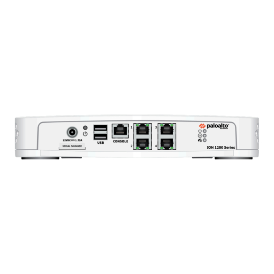
ION 1200 Overview ION 1200 Back Panel The following image shows the back panel of the ION 1200 and the table describes the back panel components. Item Component Description Serial Number Serial number of the ION device. Earthing Earth ground connection. The ground connector is not required during normal operation. -
Page 29: Ion 1200-C-Na/Row Back Panel
ION 1200 Overview ION 1200-C-NA/ROW Back Panel The back panel of the cellular ION 1200-C-NA and ION 1200-C-ROW are similar. The following image shows the back panel of the cellular ION 1200-C-NA device and ION 1200-C-ROW and the table describes the back panel components. Item Component Description... - Page 30 ION 1200 Overview Item Component Description SIM Cover SIM cover that covers the SIM slots. SIM slots 2 SIM slots for cellular network connectivity. QR Code QR code links to the SIM installation section of the Hardware Reference. Screws M3 screws. QR Code QR code links to the ION 1200 Hardware...
-
Page 31: Ion 1200-C-5G Back Panel
ION 1200 Overview ION 1200-C-5G Back Panel The following image shows the back panel of the cellular ION 1200-C-5G-WW device and the table describes the back panel components. Item Component Description 1 and 11 Antenna Connector Antenna SMA (F) connectors. Serial Number Serial number of the ION device. - Page 32 ION 1200 Overview Item Component Description QR Code QR code links to the SIM installation section of the Hardware Reference. Screws M3 screws. QR Code QR code links to the ION 1200 Hardware Reference. ION 1200 Hardware Reference 2022 Palo Alto Networks, Inc. ©...
-
Page 33: Ion 1200 Compliance Statement
ION 1200 Overview ION 1200 Compliance Statement The following lists the ION device hardware compliance statements: • VCCI: This section provides the compliance statement for the Voluntary Control Council for Interference by Information Technology Equipment (VCCI), which governs radio frequency emissions in Japan. - Page 34 ION 1200 Overview 2014/35/EU. The full text of the EU declaration of conformity for ION 1200 is available at the following link: ION 1200 The ION 1200-C-ROW and ION 1200-C5G-WW (with radio) comply with the requirements set out in the Radio Equipment Directive (2014/53/EU). The full text of the EU declaration of conformity for each model is available at the following links: •...
- Page 35 ION 1200 Overview • Federal Communications Commission (FCC) Compliance Statement • ICES (Canadian EMC Compliance Statement): This Class B digital apparatus complies with Canadian ICES-003. French Translation: Cet appareil numérique de la classe B est conforme à la norme NMB-003 du Canada.
- Page 36 ION 1200 Overview • Declaration of the Presence Condition of the Restricted Substances Marking. • Mexico Declaratory Legend: For use in Mexico, operation of this equipment is subject to the following conditions: • This equipment or device may not cause harmful interference. •...
-
Page 37: Ion 1200-S Front Panel
ION 1200 Overview ION 1200-S Front Panel The following image shows the front panel of the ION 1200-S and the table describes the front panel components. Item Component Description USB Port USB 3.0 (reserved for future use). Console Port RJ-45 Serial console port. Micro USB Micro USB Type B Console connector. - Page 38 ION 1200 Overview Item Component Description Power LED Power LED; the LED turns green when powered on. Heat Label Heat label on the device. ION 1200 Hardware Reference 2022 Palo Alto Networks, Inc. ©...
-
Page 39: Ion 1200-S-C-Na/Row Front Panel
ION 1200 Overview ION 1200-S-C-NA/ROW Front Panel The front panel of the ION 1200-S-C-NA and ION 1200-S-C-ROW are identical. The following image shows the front panel of the ION 1200-S-C-NA/ROW and the table describes the front panel components. Item Component Description USB Port USB 3.0 (reserved for future use). - Page 40 ION 1200 Overview Item Component Description Controller LED Controller LED; the LED turns green on successful connection with the Prisma SD-WAN controller. OS LED Operating System status LED. Power LED Power LED; the LED turns green when powered on. Antenna Connector Antenna SMA (F) Connectors.
-
Page 41: Ion 1200-S-C5G-Ww Front Panel
ION 1200 Overview ION 1200-S-C5G-WW Front Panel The following image shows the front panel of the ION 1200-S-C5G-WW and the table describes the front panel components. Item Component Description USB Port USB 3.0 (reserved for future use). Console Port RJ-45 Serial console port. Micro USB Micro USB Type B Console connector. - Page 42 ION 1200 Overview Item Component Description Controller LED Controller LED; the LED turns green on successful connection with the Prisma SD-WAN controller. OS LED Operating System status LED. Power LED Power LED; the LED turns green when powered on. Antenna Connector Antenna SMA (F) Connectors.
-
Page 43: Ion 1200-S Back Panel
ION 1200 Overview ION 1200-S Back Panel The following image shows the back panel of the ION 1200-S and the table describes the back panel components. Item Component Description Earthing Earth ground connection. The ground connector is not required during normal operation. Serial Number Serial number of the ION device. -
Page 44: Ion 1200-S-C-Na/Row Back Panel
ION 1200 Overview ION 1200-S-C-NA/ROW Back Panel The back panel of the cellular ION 1200-S-C-NA and ION 1200-S-C-ROW are similar. The following image shows the back panel of the cellular ION 1200-S-C-NA device and ION 1200-S- C-ROW and the table describes the back panel components. Item Component Description... -
Page 45: Ion 1200-S-C-5G Back Panel
ION 1200 Overview ION 1200-S-C-5G Back Panel The following image shows the back panel of the cellular ION 1200-S-C5G-WW device and the table describes the back panel components. Item Component Description Antenna Connector Antenna SMA (F) connectors. SIM slots 2 SIM slots for cellular network connectivity. -
Page 46: Ion 1200 Leds
ION 1200 Overview ION 1200 LEDs Refer to the ION 1200 device front panel images for position of the LEDs on the ION 1200 devices and its description. LEDs ION 1200 Power • Green LED indicates the device is powered on. •... - Page 47 ION 1200 Overview Cellular LED Cellular ION Device • Solid green LED indicates maximum signal strength. Blinking green LED indicates good to poor Radio Signal Strength Indicator. The cellular LED blinking rate is based on the signal strength: • 25 blinks in 10 seconds—Good signal strength. •...
-
Page 48: Ion 1200-S Compliance Statement
ION 1200 Overview ION 1200-S Compliance Statement The following compliance statements apply to this ION device: • VCCI—This section provides the compliance statement for the Voluntary Control Council for Interference by Information Technology Equipment (VCCI), which governs radio frequency emissions in Japan. The following information is in accordance to VCCI Class A requirements: Translation: This is a Class A product. - Page 49 ION 1200 Overview Regulations 2016, and The Restriction of the Use of Certain Hazardous Substances in Electrical and Electronic Equipment Regulations 2012. • ION 1200-S-C-ROW is in conformity with the following designated standards and fulfills the requirements of the Electrical Equipment (Safety) Regulations 2016, Electromagnetic Compatibility Regulations 2016, Radio Equipment Regulations 2017, and The Restriction of the Use of Certain Hazardous Substances in Electrical and Electronic Equipment Regulations 2012.
-
Page 50: Installation Kit Components
ION 1200 Overview Installation Kit Components The ION 1200 device installation kit contains the following parts and tools to install the device: • 1x ION 1200 device. • 1x 40W power adapter for cellular devices—ION 1200-C-NA, ION 1200-C-ROW, ION 1200- C-5G-WW. -
Page 51: Install The Ion 1200
Install the ION 1200 This chapter describes how to install the ION 1200 series: > Install Antennas > Insert SIM Cards > Install the ION 1200 on a Wall > Install the ION 1200 on a Flat Surface > Install the ION 1200 in a 19-inch Equipment Rack >... -
Page 52: Install Antennas
Install the ION 1200 Install Antennas The ION 1200-C-NA, ION 1200-C-ROW, and ION 1200-C-5G-WW devices support multi-band antennas which can be easily secured to the device. The ION 1200-C-NA and ION 1200-C-ROW have three antenna SMA (F) connectors. The ION 1200-C-5G-WW has four antenna SMA (F) connectors. - Page 53 Install the ION 1200 STEP 1 | Secure the antennas to the SMA connectors located at the corners of the device. Rotate the antennas at 180-degree movement about the SMA connectors. Tighten the antennas by hand. STEP 2 | Adjust the antenna orientation to receive optimal signal strength in your environment. It is recommended to conduct a cellular location assessment of the site to receive best signal strength before installing the ION device.
-
Page 54: Insert Sim Cards
Install the ION 1200 Insert SIM Cards The ION 1200-C-NA, ION 1200-C-ROW, and ION 1200-C-5G-WW devices support two SIM slots to enable multiple mobile network connectivity. STEP 1 | Remove the SIM cover by unfastening the two M3 screws using a type one Phillips screwdriver. - Page 55 Install the ION 1200 STEP 2 | Insert the nano SIM in SIM 1 or SIM 2 slot by pushing the SIM in the slot till it is locked in its position. The SIM chamfered corner (sloping edge) indicates the insertion orientation into the SIM slot as shown in figure below.
- Page 56 Install the ION 1200 ION 1200 Hardware Reference 2022 Palo Alto Networks, Inc. ©...
- Page 57 Install the ION 1200 STEP 3 | After inserting the SIM, place the SIM cover back on the device. To eject the SIM from the device, gently push the SIM inward using a finger tip and release it before pulling it out. ION 1200 Hardware Reference 2022 Palo Alto Networks, Inc.
-
Page 58: Install The Ion 1200 On A Flat Surface
Install the ION 1200 Install the ION 1200 on a Flat Surface The ION 1200 series ships with rubber feet attached to each corner of the device. As pictured below, the ION 1200 device can be horizontally situated on a flat surface. -
Page 59: Install The Ion 1200 On A Wall
Install the ION 1200 Install the ION 1200 on a Wall Install an ION 1200 on a drywall or plywood wall using the wall-mount kit as described in the following procedure. STEP 1 | Mark four locations on the wall that line up with the wall mount holes on the bottom of the device as shown in the Wall Mount Template. - Page 60 Install the ION 1200 into the anchor until the bottom of the screw head protrudes 1/4” (.6cm) from the wall. Repeat this step for the other three screw locations unless either is located over wood, in which case, use a .75” wood screw instead of a drywall anchor and screw. •...
- Page 61 Install the ION 1200 STEP 4 | Install the power adapter in the wall-mount bracket using the Velcro strap and cable tie. Make sure to align the cable tie with the notches in the bracket to prevent the power cord from falling out.
- Page 62 Install the ION 1200 ION 1200 Hardware Reference 2022 Palo Alto Networks, Inc. ©...
-
Page 63: Wall Mount Template
Install the ION 1200 Wall Mount Template Download and print the following wall mount template to secure the template to the wall where you intend to mount the ION 1200 device and use it to mark the location for each of the four wall-mount screws. -
Page 64: Install The Ion 1200 In A 19-Inch Equipment Rack
Install the ION 1200 Install the ION 1200 in a 19-inch Equipment Rack The racktray kit enables you to install an ION 1200 device in a 19" rack. The installation hardware consists of a metal base and two rails. To ease installation, first install the device in the racktray and then install the assembled racktray into the equipment rack. -
Page 65: Install The Ion 1200 Using The Racktray
Install the ION 1200 Install the ION 1200 Using the Racktray Mount the ION device in a 19” equipment rack using the racktray. The mounting equipment requires 1 RU of rack space. Maintain a minimum of 7.5" height clearance for the antennas in the rack. STEP 1 | Slide one of the adjustable mounting brackets into one of the fixed mounting brackets to create a mounting rail. - Page 66 Install the ION 1200 STEP 3 | Secure the rails to the equipment frame with mounting screws (not provided) compatible with your equipment frame. Tighten the screws to their recommended torque value. ION 1200 Hardware Reference 2022 Palo Alto Networks, Inc. ©...
- Page 67 Install the ION 1200 STEP 4 | With the front of the device facing forward, align the four rubber feet on the bottom of the device to the slotted holes in the provided mounting tray. ION 1200 Hardware Reference 2022 Palo Alto Networks, Inc. ©...
- Page 68 Install the ION 1200 STEP 5 | Secure the device in place using three of the provided #6-32 x 3/16” Long Flathead screws. ION 1200 Hardware Reference 2022 Palo Alto Networks, Inc. ©...
- Page 69 Install the ION 1200 STEP 6 | Slide the device power supply into the marked position and fasten the provided velcro strap around the power supply until it is secure in place. ION 1200 Hardware Reference 2022 Palo Alto Networks, Inc. ©...
- Page 70 Install the ION 1200 STEP 7 | Plug the power supply connector into the back of the device. Using the provided tie-wraps, bind and secure the power supply cable to the metal hooks in the mounting tray. STEP 8 | Slide the mounting tray into the rails previously fixed to the equipment rack.
- Page 71 Install the ION 1200 STEP 9 | Align the slotted holes in the mounting tray to the holes in the equipment frame. Secure the mounting tray to the equipment frame on both sides using 3 screws each (not provided). The screws must be compatible with your equipment frame.
-
Page 72: Power On The Ion 1200
Install the ION 1200 Power on the ION 1200 Connect the power cables to the ION device and plug the device power cable into an AC power outlet. When you switch on the power, the device powers on and the power indicator turns green. -
Page 73: Install Ion 1200-S
Install ION 1200-S This chapter explains the installation procedure for the ION 1200-s device: > Install Antennas in the ION 1200-S > Insert SIM Cards in the ION 1200-S > Install the ION 1200-S on a wall > ION 1200-S Wall Mount Template >... -
Page 74: Insert Sim Cards In The Ion 1200-S
Install ION 1200-S Insert SIM Cards in the ION 1200-S The ION 1200-S-C-NA, ION 1200-S-C-ROW, and ION 1200-S-C5G-WW devices support two SIM slots to enable multiple mobile network connectivity. STEP 1 | Remove the SIM cover by unfastening the two M3 screws using a type one Phillips screwdriver. -
Page 75: Install Antennas In The Ion 1200-S
Install ION 1200-S Install Antennas in the ION 1200-S The ION 1200-S-C-NA, ION 1200-S-C-ROW, and ION 1200-S-C5G-WW devices support multi- band antennas which can be easily secured to the device. The ION 1200-S-C-NA and ION 1200- S-C-ROW have three antenna SMA (F) connectors. The ION 1200-S-C5G-WW has four antenna SMA (F) connectors. - Page 76 Install ION 1200-S STEP 1 | Secure the antennas to the SMA connectors located at the corners of the device. Rotate the antennas at 180-degree movement about the SMA connectors. Tighten the antennas by hand. STEP 2 | Adjust the antenna orientation to receive optimal signal strength in your environment. It is recommended to conduct a cellular location assessment of the site to receive best signal strength before installing the ION device.
-
Page 77: Install The Ion 1200-S On A Wall
Install ION 1200-S Install the ION 1200-S on a wall Install an ION 1200-S on a drywall or plywood wall using the wall-mount kit as described in the following procedure. STEP 1 | Mark four locations on the wall that line up with the wall mount holes on the bottom of the device as shown in the ION 1200-S Wall Mount Template. - Page 78 Install ION 1200-S STEP 3 | Align the four holes on the bottom of the device with the four screws on the wall and hang the device on the screws. Make sure the device is securely connected to each of the four screws before you let go.
- Page 79 Install ION 1200-S STEP 4 | Install the power adapter in the wall-mount bracket using the Velcro strap and cable tie. Make sure to align the cable tie with the notches in the bracket to prevent the power cord from falling out. After you secure the power adapter to the bracket, mount the bracket next to the device using wood or drywall screws as appropriate.
-
Page 80: Ion 1200-S Wall Mount Template
Install ION 1200-S ION 1200-S Wall Mount Template Download and print the following wall mount template to secure the template to the wall where you intend to mount the ION 1200-S device and use it to mark the location for each of the four wall-mount screws. -
Page 81: Install The Ion 1200-S On A Rack
Install ION 1200-S Install the ION 1200-S on a Rack Mount the ION device in a 19” equipment rack using the racktray. The mounting equipment requires 1 RU of rack space. The racktray kit enables you to install an ION 3200 device in a 19" rack. The installation hardware consists of a metal base and two rails. - Page 82 Install ION 1200-S STEP 1 | Slide one of the adjustable mounting brackets into one of the fixed mounting brackets to create a mounting rail. Repeat for the second mounting rail. The adjustable and fixed brackets are the same for the left and right side. You may also use the two-post configuration to rack mount the device using a cross-bar at the rear to prevent the racks from flaring out.
- Page 83 Install ION 1200-S STEP 3 | Secure the rails to the equipment frame with mounting screws (not provided) compatible with your equipment frame. Tighten the screws to their recommended torque value. STEP 4 | Slide the power adapter into the marked position and attach the AC cord, route the AC cord to the right side of the tray sidewall and underneath the front tray “C”...
- Page 84 Install ION 1200-S STEP 6 | Plug the power supply connector into the back of the device. Using the provided tie-wraps, bind and secure the power supply cable toward the back end of the tray using the sheet- metal lances toward the center of the tray. STEP 7 | After assembling the device to the tray and connecting the power cable to the device, tie- wrap the power cord to the "C"...
- Page 85 Install ION 1200-S STEP 10 | Align the slotted holes in the mounting tray to the holes in the equipment frame. Secure the mounting tray to the equipment frame on both sides using 3 screws each (not provided). The screws must be compatible with your equipment frame. STEP 11 | Proceed to Power on the ION...
- Page 86 Install ION 1200-S ION 1200 Hardware Reference 2022 Palo Alto Networks, Inc. ©...
-
Page 87: Troubleshoot Ion 1200
Troubleshoot ION 1200 This section lists the most common issues that you may face. Troubleshoot the issue by following the resolution steps mentioned in the table. > Troubleshoot Common Issues with the ION 1200... -
Page 88: Troubleshoot Common Issues With The Ion 1200
Troubleshoot ION 1200 Troubleshoot Common Issues with the ION 1200 Troubleshoot the issue by following the resolution steps mentioned in the table. If the issue persists, contact Palo Alto Networks Support. Alerts and alarms are reported when there is fault in the system or an issue with the cellular modem. - Page 89 Troubleshoot ION 1200 Issue Resolution issues with the service provider rather than your modem. 8. You might need to add a custom or a private APN profile. Contact your mobile broadband service provider for APN information. 1. Check the Signal Strength LED. Interface flapping 2.
- Page 90 Troubleshoot ION 1200 Issue Resolution 3. Call Palo Alto Networks support if the issue is still not resolved. The main power usage goes over the Check the PD power requirements for the port and configured threshold for the system or all the PDs.Validate whether the power usage for the for a port.
Need help?
Do you have a question about the ION 1200 Series and is the answer not in the manual?
Questions and answers