
Subscribe to Our Youtube Channel
Related Manuals for DEMAG DRC-MJ D3


Summary of Contents for DEMAG DRC-MJ D3
- Page 1 User manual/assembly instructions DRC-MJ D3 hand-held transmitter 43666644.eps 081019 enGB 211 338 44 719 IS 975...
-
Page 2: Table Of Contents
Putting DRC radio controls into operation for the first time Safety warnings Safety instructions for operation Personnel requirements Putting into operation Putting a radio control system into operation with a DRC-MJ D3 hand-held transmitter Single-transmitter operation Configuration of a radio control system for DRC-DR Releasing a receiver... - Page 3 11.1 Personnel requirements 11.2 Disposal of the radio control system Information 12.1 After-sales service Menu for programming the DRC-MJ D3 hand-held transmitter parame- ters P1.1 Activating the menu P1.2 Further information on the parameters P1.3 Displaying and entering reversal of the direction of the lifting/lowering mo- tion, parameter code 507 P1.4...
-
Page 4: General
1.2 Information on the This user manual/assembly instructions is an integral part of the DRC-MJ D3 hand-held transmitter. user manual/assembly They must be kept available in the immediate vicinity at all times. -
Page 5: Safety
Safety 2.1 General The “Safety” section provides you with an overview of all important safety aspects which are necessary for you and for the protection of individuals who work with and on the product as well as for safe and smooth operation with the product. Further task-related safety warnings can be found in the descriptive sections on the individual life-cycle phases of the product. -
Page 6: Intended Use
2.3 Intended use DRC-MJ D3 hand-held transmitter are intended to be used as control units and transmitter stations for DRC-DR and DRC-MP radio receivers. The radio receiver is only referred to as DRC in the description below and, therefore, stands for both DRC-DR and DRC-MP receivers. -
Page 7: Operating Personnel Requirements
2.4 Operating personnel requirements 2.4.1 Responsibility of the owner Owner The owner is the person who operates the product for commercial purposes or lends it to third parties for use/operation. While it is use, the owner bears legal product responsibility for the protection of individuals who work on or with the product or any third parties. -
Page 8: Personal Protection Equipment
2.4.3 Target groups Designation Activities Qualification Operator • Checks correct operation of the safety devices • Has been trained to operate the product • Operates the product • Has been informed about possible hazards resulting from inappropriate conduct Repair personnel •... -
Page 9: Spare Parts
2.7 Regular inspections The owner of DRC-MJ D3 hand-held transmitters may be obliged to carry out regular inspections by national industrial safety legislation and regional regulations. This is regulated by the rules and regulations of the German Social Accident Insurance (DGUV) in the Federal Republic of Germany, for example. -
Page 10: Device Selection
• 1 plug-in charger (rechargeable battery) 110 – 230 V 50/60 Hz 773 438 44 • 1 DRC-MJ D3 hand-held transmitter user manual/assy. instructions 211 338 44 • 1 set of button symbols for DRC-MJ D3 hand-held transmitter 773 465 44 3.2 Available radio... - Page 11 Frequency range 2,4 GHz ISM band (2405 - 2480 MHz) Enclosure Type of enclosure IP 55 Weight DRC-MJ D3 hand-held transmitter with battery 450 g DRC-MJ D3 hand-held transmitter without battery 395 g Battery charger Supply voltage 110 - 230 V, 50/60 Hz...
-
Page 12: International Postal Approval
4.2 International postal DRC D3 transmitters and radio receivers in the standard delivery form can be operated without any registration or operating fee in the following countries: approval Countries Frequency range Austria Belgium Bulgaria China Croatia Cyprus Czech Republic Denmark Estonia Finland France... -
Page 13: Transport, Packing, Storage
Transport, packing, storage 5.1 Transport inspection • Check that the delivery is complete and check it for any transport damage immediately on receipt. • If any transport damage is visible from the outside, only accept the delivery on condition. Note the scope of damage in the shipping documents/delivery note of the forwarding company and lodge a claim. -
Page 14: Design And Function
This user manual/assembly instructions refers to DRC-MJ D3 hand-held transmitters in combination with matching DRC radio receivers. • The Demag DRC-DR radio receiver is a PCB that is designed to be installed in the electric equipment cover of a DR or DMR hoist unit. The interface of this receiver component to the crane control system is the CAN safety bus and the power supply via the DR/DMR electric equipment. -
Page 15: Power Supply For Drc-Mj Hand-Held Transmitters
60 hours for DRC-MJ D3 hand-held transmitters when they are switched If only a residual charge is shown, connect the DRC-MJ D3 hand-held transmitter to the charger at the next opportunity. If the battery icon is empty, the DRC-MJ D3 hand-held transmitter must be immediately connected to the charger. - Page 16 To charge the batteries, proceed as follows: – Plug the charger unit into a power socket. – Plug the connecting cable into the charger socket of the DRC-MJ D3 hand-held transmitter. icon will appear on the screen. The red LED fl ashes at 2 Hz.
- Page 17 New rechargeable batteries must fit tightly between the contact surfaces. NOTE If primary cells are used in the DRC-MJ D3 hand-held transmitter, it must not be connected to the charger to avoid any damage caused by overheating during the attempt to charge them.
-
Page 18: Identification And Screen Functions
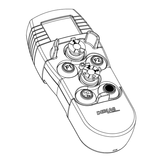
Charging socket on the side of the housing Horn STOP button 43666844.eps The LED in the DRC-MJ D3 hand-held transmitter indicates the operating status of the hand-held transmitter: Operating status Hand-held transmitter is switched off or in Standby mode Red continuously on... - Page 19 19 for hoist unit functions) 6.4.2 with LED screen The DRC-MJ D3 hand-held transmitter has a screen. All important data that are needed for operation of the crane to be controlled are shown on the screen.
- Page 20 6.4.2.1 General display Crane ID K564 The crane ID shows the crane to which the DRC-MJ D3 hand-held transmitter has been assigned. The crane ID is saved in the DRC radio receiver and can only be entered via the DRC-MJ D3 hand-held transmitter.
- Page 21 STOP indicates STOP mode. The system can be switched into Run mode with the electronic key. See section 8.4.1 “No radio signal” icon The “No radio signal” icon is displayed if the DRC-MJ D3 hand-held transmitter fails to establish a connection to the assigned DRC radio receiver.
- Page 22 Icons in the first main row Fault icon The fault icon is displayed if there is a fault. The fault code is displayed in the row below. If there are several faults at the same time, the code displayed changes in cycles. Overload icon The overload icon is displayed if there is an overload.
- Page 23 The coding labels are used to show the crane ID on the crab or the crane. The crane identification shown by the coding labels must be identical to the crane identification shown on the screen of the DRC-MJ D3 hand-held transmitter. Black background foil Part no.
- Page 24 Part no.: 895 638 44 The travel direction foils must be attached to the hoist unit so that they are easily visible to match the relevant travel directions and the direction of movement symbols on the DRC-MJ D3 hand-held transmitter.
-
Page 25: Putting Drc Radio Controls Into Operation For The First Time
NOTE This user manual/assembly instructions must be read carefully before starting any work on and with the DRC-MJ D3 hand-held transmitter, especially before the unit is put into operation for the first time. The manufacturer assumes no liability for any damage which results from the following. -
Page 26: Personnel Requirements
The range may also be limited if the available frequency range is being used by other radio transmitters. The quality of the radio signal is shown on the screen of the DRC-MJ D3 hand-held transmitter. If poor connection quality is displayed, unintended interruptions of the controlled movements can occur. - Page 27 When the unit is switched off, no icons appear on the screen, the LED is off. 7.5.1 Switching the hand-held transmitter on 1. Press the STOP button to switch the DRC-MJ D3 hand-held transmitter on. 2. STOP appears on the display. Press 1 x 43678844.eps...
-
Page 28: Single-Transmitter Operation
A globally unique assignment of the hand-held transmitter to the radio receiver to be controlled on the crane can be created by logging the DRC-MJ D3 hand-held transmitter to a DRC radio receiver. Both DRC-MJ D3 hand-held transmitters as well as DRC radio receivers are provided with unique address features that are shared during the log-on process to ensure distinct and unique assignment. - Page 29 Select radio receiver based on crane ID NOTE A DRC-MJ D3 hand-held transmitter only needs to be logged onto to a DRC radio receiver with code NOID when the unit is put into operation for the first time in order, subsequently, to assign the crane ID specified in section 7.6.3 to the DRC radio receiver.
- Page 30 ID is shown in the 2nd main row of the screen (NOID: M24 in the example). At the same time, the crane ID on the DRC-MJ D3 hand-held transmitter is also changed to the new value and displayed next to the battery icon.
- Page 31 DRC radio receiver into operation is a safety-relevant process that must only be performed by authorised specialist personnel. After successful establishment of a radio connection between the DRC-MJ D3 hand-held transmitter and the DRC radio receiver, the crane identification specified according to section 6.4.4 must be assigned to the radio receiver.
-
Page 32: Configuration Of A Radio Control System For Drc-Dr
7.7 Configuration of a DR/DMR cranes that are equipped with a DRC-DR radio receiver use an extended scope of functions on DRC-MJ D3 hand-held transmitters. They are used to radio control system configure the crane control system and to display information. -
Page 33: Releasing A Receiver
7.8 Releasing a receiver When a new transmitter is logged on with the wireless log-on procedure used for DRC D3 radio systems, the previously used DRC radio receiver must be enabled. In the simplest case, the DRC radio receiver can be released by the previously logged-on transmitter (for other ways to enable the DRC radio receiver, see section 7.9.3 on page 38): –... - Page 34 Select Select crane/crab via LEFT and RIGHT 43679544.eps – Press the F2 key to confirm selection of “????”. Release of the receiver is initiated. The receiver outputs a short horn signal to indicate the successful log-off or release of the receiver. The screen shows the following: ???? STOP...
-
Page 35: Multiple Transmitter Operation
7.9 Multiple transmitter operation 7.9.1 Logging on a second or third Up to three radio transmitters can be logged onto one DRC radio receiver. radio transmitter The system ensures that travel commands can only ever be sent by one radio transmitter. - Page 36 – Quit the parameter menu with the LIFT joystick. The screen shows: K564 STOP 43603744.eps 2. To log on a further radio transmitter, the previously logged-on radio transmitter must be switched off or changed to Standby mode – Hold the STOP button down and push the LOWER joystick 6 times to switch the radio transmitter off –...
- Page 37 – Select the DRC radio receiver with the RIGHT or LEFT joystick. ???? K564:1 43604044.eps The digit after the crane ID indicates the number of radio transmitters that are pre-paired with the DRC radio receiver. – Press the F2 key to confirm the required DRC radio receiver. After a few seconds, the screen shows: K564 STOP...
- Page 38 – Press the HORN pushbutton to confirm that the new radio transmitter has taken over control. The radio transmitter is actively connected to the DRC radio receiver. The transfer icon disappears. The radio control system can now be switched into Crane operation/Run mode by entering the electronic On key (see section 8.4 on page 43): –...
- Page 39 – Push the RIGHT or LEFT joystick until parameter 000 appears on the screen: ???? 000: T # R 43604244.eps – Press the F1 key. ???? 000= C−−−− 43604644.eps – If you prefer to enter the crane serial no. instead of the crane ID, push the RIGHT or LEFT joystick and confirm your choice with the F1 key.
- Page 40 7.9.4 Logging-off individual radio If one of the paired radio transmitters is lost or has to be replaced, individual transmitters radio transmitters can be deleted from the DRC radio receiver’s list of pre-paired transmitters. Call up the DRC radio receiver’s parameter menu as follows: –...
-
Page 41: Using Drc Radio Controls
Using DRC radio controls 8.1 Safety warning Warning. Incorrect operation Incorrect operation can result in severe injuries and/or damage to property. The DRC radio control system may only be operated by authorised and trained personnel in compliance with all accident-prevention and safety regulations. •... -
Page 42: Check Before Starting Work
Press 1 x 43678844.eps The “DEMAG” logo first appears on the display. When a connection to the DRC radio receiver has been established, the following must be displayed: • Crane identification of the assigned DRC radio receiver • Icon to display the radio signal quality •... -
Page 43: Crane Operation/Run
The LED in the display fi eld fl ashes green if Run mode is switched on after entry. 8.4.2 Functions in crane operation DRC-MJ D3 hand-held transmitters use so-called mini-joystick control elements to control the three motion axes. Thanks to these control elements, a DRC-MJ hand-held transmitter has the... - Page 44 The speed-limit function can be set to 30, 50 or 70% of the maximum speed (by programming parameters). On DRC-MJ D3 hand-held transmitters that have a variable joystick, the speed limit is set according to the programmed speed threshold (30%, 50% or 70% of the maximum speed).
- Page 45 Activating the speed-limit function If the parameters have been programmed for at least one speed threshold (<100%), activate the speed-limit function as follows: Green Press Press Hold down 43679744.eps 43678844.eps 43679144.eps 1. Hold the STOP button down during the log-on process. 2.
- Page 46 Deactivating the speed-limit function If you want to deactivate the speed-limit function again, proceed as follows: Green Press Press Hold down 43679744.eps 43678844.eps 43679144.eps 1. Hold the STOP button down during the log-on process. 2. Transmitter is in STOP mode 3.
-
Page 47: Taking The Equipment Out Of Service At The End Of The Shift (Standby Or Switching Off)
8.5 Taking the equipment At the end of a shift and during longer breaks, DRC-MJ D3 hand-held transmitters must be switched to Standby mode or switched off completely by the key out of service at the sequence as shown to protect the installation against unauthorised use and to end of the shift (stand- reduce power consumption of the DRC-MJ D3 hand-held transmitter. -
Page 48: Radio Control System Operating Statuses
The screen shows STOP. No travel commands are transmitted in STOP mode. The emergency-stop contact in the DRC radio receiver is open. The radio connection to the DRC radio receiver is maintained. A DRC-MJ D3 hand- held transmitter will automatically switch to Standby mode if no button is actuated following a timeout period of 5 minutes. - Page 49 8.6.5 Hand-held transmitter reset A DRC-MJ D3 hand-held transmitter can be reset by removing the battery pack for a short time. The battery pack can be reached by carefully pulling off the lower rubber cap: Pull off rubber cap 43680044.eps...
-
Page 50: Information Menu In Connection With Drc-Dr
This information is stored in the form of a list by each DR/ DMR control system. One element of this list is requested by the DRC-MJ D3 hand-held transmitter and made available by the selected control system via the CAN bus. -
Page 51: Information Menu Data
9.6 Information menu data The following data can be displayed via the Information menu: Code Information Remaining duration of service in % (determined from load spectrum), not available for DR-Com rope hoists. Example: Operating hours Display for remaining service Basic value for full load hours (with reference to rated load for size) life Gearbox transmission ratio K564... -
Page 52: Fault Elimination
10 Fault elimination Before taking any fault elimination measures on the radio control system, first check that the crane installation is supplied with power and is ready for operation and has not been switched off by any safety devices (mains connection switch, crane isolating switch, emergency-stop switch, travel and lifting path limitation devices, overload protection device, motor circuit-breakers, etc.). - Page 53 No. Problem Screens Possible causes Information, document section K123 Take the other DRC-10 hand-held Another DRC-MJ hand-held 08 The displayed crane transmitter out of service, 8.5. transmitter has been logged on for does not respond Log DRC-MJ hand-held the crane transmitter on again, 7.6.2.
- Page 54 No. Problem Screens Possible causes Information, document section Check connection to charger 15 The batteries are not and mains connector. Replace No power from charger being charged defective plug-in charger, if necessary. K564 STOP Check connection to charger 16 The batteries are not and mains connector.
-
Page 55: Disposal
11 Disposal 11.1 Personnel requirements 11.1.1 Target group Designation Activities Qualification Repair personnel • Repairs malfunctions and defects • Trained specialist personnel with mechanical or electrical training • Takes the product out of operation • Has been trained in the repair of the product by the •... -
Page 56: Information
12 Information 12.1 After-sales service Our after-sales service will provide you with all technical information on Demag products and their systematic application. If you have any questions regarding our products, please refer to one of our after- sales service centres, the relevant representative or our head office in Wetter. - Page 57 EC conformity declaration...
- Page 58 (For authorised personnel only) User manual/assembly instructions DRC-MJ D3 hand-held transmitter parameter programming Target groups Designation Activities Qualification Service personnel • Performs safety-related modifications or repairs to the product • Trained specialist personnel with mechanical or electrical training • Is authorised to be present in the entire surroundings of the machine •...
-
Page 59: Menu For Programming The Drc-Mj D3 Hand-Held Transmitter Parame- Ters
P1 Menu for programming the DRC-MJ D3 hand-held transmitter parameters The “Hand-held transmitter parameter programming” menu can be used by specially trained personnel for displaying and also partly changing the following settings of the DRC-MJ D3 hand-held transmitter: Parameter no. -
Page 60: P1.2 Further Information On The Parameters
Use the RIGHT and LEFT joystick to select the parameter to be displayed. The LIFT joystick can be used to exit the menu at any time. The F1 key can be used to change to entry and selection mode for certain parameters that can be edited (Edit column = Yes). - Page 61 Can be set at 2 levels: 0 = off, 1 = on Default: 1 Note: The vibration alarm drains the rechargeable battery capacity of DRC-MJ D3 hand- held transmitters: de-activating the vibration alarm can, therefore, extend the operating period for a battery charge.
- Page 62 P1.3 Displaying and This parameter makes it possible to reverse the direction of movement of the up- per mini joystick for the lifting/lowering motion. entering reversal The default setting is 0, i.e. the mini joystick must be pulled towards the operator of the direction of for lifting.
-
Page 63: P1.4 Activating The Electronic Gate For The Left Joystick, Parameter Code 508
P1.4 Activating the Parameter 508 is used to set whether both axes of the left joystick can be controlled at the same time (e.g. diagonal travel) or only separately (cross template electronic gate for function). the left joystick, This function represents the electronic simulation of a mechanical gate. The axis parameter code 508 which is first selected by movement of the joystick is enabled for operation, while the second axis is disabled. -
Page 64: P2 Fcc And Industry Canadian Information
P2 FCC and Industry Canada information P2.1 FCC information This device complies with part 15 of the FCC Rules. Operation is subject to the following two conditions: (1) This device may not cause harmful interference, and (2) this device must accept any interference received, including interference that may cause undesired operation. - Page 65 Notizen...
- Page 66 Notizen...
- Page 67 Notizen...
- Page 68 PO Box 67 · 58286 Wetter, Germany Phone +49 (0)2335 92-0 +49 (0)2335 92-7676 www.demagcranes.com Reproduction in whole or in part only with prior consent of Demag Cranes & Components GmbH, 58286 Wetter, Germany. Subject to change. No liability for errors or omissions.
Need help?
Do you have a question about the DRC-MJ D3 and is the answer not in the manual?
Questions and answers