
Subscribe to Our Youtube Channel
Related Manuals for Alfa Laval HS-LA FILLER


Summary of Contents for Alfa Laval HS-LA FILLER
- Page 1 Operations & Maintenance Manual HS-LA FILLER Machine Serial No. : 2016-094 Project No. : 21R60.BA 0180 Ver. 01 Original instructions...
- Page 3 1.2.1 GENERIC OPERATOR: ..................2 1.2.2 MECHANICAL MAINTENANCE: ................. 2 1.2.3 ELECTRICAL MAINTENANCE: ................2 1.2.4 ALFA LAVAL TECHNICIAN: ................2 GUARANTEE ......................3 1.3.1 SCOPE OF THE GUARANTEE ................3 1.3.2 DURATION OF THE GUARANTEE ..............3 1.3.3 APPLICATION OF THE GUARANTEE ............... 4 1.3.4...
- Page 4 GENERAL INDEX RECEPTION AND CONTROL OF THE MACHINE ..........32 2.2.1 TRANSPORT ....................32 2.2.2 ADOPTION OF PROTECTION DEVICES ............34 MACHINE ............35 2.2.3 PACKING OF THE 2.2.4 HANDLING AND LIFTING OF THE PACKING ..........37 2.2.5 UNPACKING AND INITIAL INSPECTION ............40 2.2.6 PACKAGING DISPOSAL ..................
- Page 5 GENERAL INDEX MACHINE LEVELLING ....................6 4.5.1 LEVELLING CHECK POINTS ................7 MACHINE ASSEMBLING ..................9 4.6.1 LIGHT TOWER INSTALLATION ............... 10 CONNECTIONS ....................... 11 4.7.1 CONNECTION TO UTILITIES AND PRODUCTION LINE ........ 11 4.7.2 ELECTRIC CONNECTIONS ................11 ROTATION OF ELECTRIC MOTORS ..............13 INSTRUCTIONS FOR THE OPERATOR ............1 CHECKING BEFORE STARTING ................
- Page 6 GENERAL INDEX CRITICAL CONTROL POINTS ................62 OPERATIVE PHASES DESCRIPTION ..............63 5.6.1 PRODUCTION ....................63 5.6.2 SIP ........................63 5.6.3 CIP ........................64 ALARMS ........................65 GUARDS SAFETY SWITCHES BYPASS ............... 69 FORMAT CHANGING ....................71 5.10 EMERGENCY STOP ....................74 5.11 RESTARTING THE MACHINE AFTER IT HAS STOPPED ........75 5.12 MACHINE STANDSTILL FOR OVER THREE MONTHS ........
- Page 7 GENERAL INDEX SUGGESTED SPARE PARTS ................1 SPARE PART LIST ....................1 SPARE PARTS TABLE .....................8 7.2.1 INTRODUCTION ....................8 7.2.2 DESCRIPTION OF CONTENTS OF SPARE PART TABLES ......8 7.2.3 HOW TO INTERPRET THE SPARE PART TABLES .......... 9 7.2.4 FILLING VALVE ASSEMBLY - 70-57-003-02 ............ 10 7.2.5 VALVE STEAM DIFFUSER ASSEMBLY - 70-57-005-01 .........
- Page 8 GENERAL INDEX HOW TO ORDER SPARE PARTS ................68 7.3.1 USE OF THE CATALOGUE ................68 7.3.2 TO ORDER SPARE PARTS ................68 7.3.3 CARD FOR SPARE PARTS ORDERING ............69 LAYOUT - FLOW SHEET - ELECTRIC AND PNEUMATIC DIAGRAM ....1 LAYOUT 01.00.1908-00 .....................1 P&ID 05.04.1330-02 ....................3 8.2.1...
- Page 9 Do not attempt tampering the calibration of any component or part of the plant unless expressly authorized in writing by Alfa Laval. Any calibration carried out by Alfa Laval at the time of testing has the purpose of ensuring the plants safety and trouble free operation: Any unauthorized tampering will entail the forfeiture of the guarantee.
- Page 10 Technician qualified to operate the plant during its standard running and charged with all the elec- trical adjustments, maintenance and repairing. They are allow to operate inside the control cabinet and the connector block with tension connected. 1.2.4 ALFA LAVAL TECHNICIAN: Qualified technician supplied by Alfa Laval for complex services. HS-LA FILLER_IM_E...
- Page 11 1.3.1 SCOPE OF THE GUARANTEE Alfa Laval guarantees the good quality and workmanship of its products and shall ● During the specified guarantee period ● Repair or replace free of charge any part whose failure or premature wear and tear are the result of poor quality of materials, defective workmanship or assembling.
- Page 12 1.3.5 HOW TO RETURN THE DEFECTIVE MATERIAL Before returning to Alfa Laval any part for which a replacement/ repair under guarantee is claimed, the necessary approval shall be obtained from Alfa Laval’s Customer Service. All parts shall be properly packed to avoid any damage in transit, and accompanied by: Reference to the purchase order number;...
- Page 13 For the first start-up of the machine, we recommend that an Alfa Laval engineer should be pres- ent, in order to check that the wiring has been executed correctly and that the machine has been properly installed, in addition to providing any additional information or instruction to the operators and service personnel with reference to this Manual.
- Page 14 The license acquired with the equipment, does not imply any right to updates. However, if Alfa Laval provides updates, they would fall under this contract. INTELLECTUAL PROPERTY All rights are and will remain assigned to Alfa Laval. The purchase of equipment does not include the acquisition of any intellectual property. HS-LA FILLER_IM_E...
- Page 15 CHAPTER 1 INTRODUCTION TECHNICAL REFERENCE STANDARDS The machine complies with the following standards, where applicable: EEC Directives DIRECTIVE 2006/42/EC Machinery directive. DIRECTIVE 2014/35/EU Low voltage. DIRECTIVE 2014/30/EU Electromagnetic compatibility. Harmonised Standards UNI EN ISO 12100:2010 : Safety of machinery - General principles for design - Risk assessment and risk reduction UNI EN ISO 13857:2008 : Safety of machinery - Safety distances to prevent danger zones being reached by the upper and lower limbs.
- Page 16 CHAPTER 1 INTRODUCTION International Standards UNI EN ISO 3746:2011 : Acoustics - Determination of sound power levels and sound energy lev- els of noise sources using sound pressure - Survey method using an enveloping measurement surface over a reflecting plane UNI EN ISO 3744:2010 : Acoustics - Determination of sound power levels and sound energy levels of noise sources using sound pressure.
- Page 17 In case of total or partial loss of the present Instruction Manual, you should inform Alfa Laval and ask for supplementary copies. Alfa Laval, reserves the right to send the documents to the customer, at the expenses of the Customer.
- Page 18 CHAPTER 2 GENERAL INFORMATION Before starting to operate the equipment the operator should perfectly know the function, the posi- tion of the whole controls of the machine and of the technical functional characters of the same. If the machine is not used in the conditions quoted in the present instruction manual, the manu- facturer declines any responsibility to people or things that could occur.
- Page 19 CHAPTER 2 GENERAL INFORMATION 2.1.2.1 CLOTHING The clothing with which the operators must be equipped must be made of resistant material; it must also let the operator move easily according to the movements that the operator has to perform. 2.1.2.2 FOOTWEAR Shoes must feature an anatomic anti-stress insole for the comfort of the foot and the upper part must be impenetrable to contact with the product to be used.
- Page 20 CHAPTER 2 GENERAL INFORMATION 2.1.2.6 BREATHING MASKS They must be wear following the producer instructions and must guarantee a suitable and perfect fitting for the operator's face. They must also feature a speech diaphragm to ensure good communication The oxygen concentration of the ambient atmosphere must be at least 19.5 % Volume;...
- Page 21 CHAPTER 2 GENERAL INFORMATION 2.1.5 THE OPERATOR SHOULD ALWAYS ● Keep in an easily and quickly accessible place the present instruction manual. ● Keep in order the work place. A behaviour not in conformity with this logics involves a danger. ●...
- Page 22 CHAPTER 2 GENERAL INFORMATION 2.1.6 DANGEROUS AREAS – WORKING AREAS The operator should act in these work areas (see the following drawing): ● Operator areas (inside the green area): in front of the machine electrical panel during production; in the back of the machine electrical panel for starting and stopping the work cycle (power on - power off);...
- Page 23 CHAPTER 2 GENERAL INFORMATION Dangerous area Operator area Maintenance/Adjustment area Bags dragging and filling area Steam group HS-LA FILLER_IM_E...
- Page 24 CHAPTER 2 GENERAL INFORMATION 2.1.7 SAFETY SYMBOLS Many of the quoted warnings can be summed up in the following illustrated signs. These symbols can be used in the manual to put in evidence particularly important indications. ATTENTION: CAREFULLY READ NOTE BESIDE. THIS SYMBOL INDICATES IMPORTANT WARNING MESSAGE WHICH ARE FUNDAMENTAL FOR THE OPERATOR AND MACHINE SAFETY.
- Page 25 CHAPTER 2 GENERAL INFORMATION ATTENTION GENERAL DANGER DANGER TO LIMBS (CATCHING, CUTTING, TRAPPING, CRUSHING). DANGER CORROSIVE MATERIAL ATTENTION NOT TO GO UP ON THE ROLLER. IT IS FORBIDDEN TO REPAIR MOVING PARTS RISK OF HIGH VOLTAGE RISK OF SURFACES WITH HIGH TEMPERATURES RISK OF SLIPPING RISK OF FALLING RISK OF TRIPPING...
- Page 26 CHAPTER 2 GENERAL INFORMATION USE BY UNAUTHORISED PERSONNEL IS FORBIDDEN IT IS FORBIDDEN TO REMOVE SAFETY GUARDS AND SAFETY DEVICES IT IS FORBIDDEN TO REPAIR AND/OR LUBRICATE MOVING PARTS IT IS FORBIDDEN TO STAND UNDER THE FORKS IT IS FORBIDDEN TO STAND ON THE FORKS ACCESS IS FORBIDDEN BY UNAUTHORISED PERSONNEL IT IS FORBIDDEN TO USE WATER TO PUT OUT FIRES ON THE ELECTRIC BOARD...
- Page 27 CHAPTER 2 GENERAL INFORMATION 2.1.8 SAFETY SYMBOLS POSITION TEMPERATURE HS-LA FILLER_IM_E...
- Page 28 CHAPTER 2 GENERAL INFORMATION HS-LA FILLER_IM_E...
- Page 29 CHAPTER 2 GENERAL INFORMATION HS-LA FILLER_IM_E...
- Page 30 CHAPTER 2 GENERAL INFORMATION 2.1.8.1 MAIN SWITCH The machine is equipped with a main switch which interrupts the general supply. The handle of the main switch of the machine is located on the electric panel, at the front, and can be locked with a padlock in the open switch position (see map of the general switch and emergency button).
- Page 31 CHAPTER 2 GENERAL INFORMATION 2.1.8.2 EMERGENCY BUTTONS The machine is fitted with mushroom emergency buttons, red with a yellow back- ground, which immediately stop the machine controlling all the other operations. (see map of the general switch and emergency button). These safety devices must be used: In the event of an imminent danger or mechanical accident;...
- Page 32 CHAPTER 2 GENERAL INFORMATION 2.1.8.3 WARNING LAMP (IF FORESEEN) A warning lamp is a column of warning lights: 1. A red light indicates an abnormal or impending critical condition. This is a condition that stops the WORKING step and calling for action by the operator. 2.
- Page 33 CHAPTER 2 GENERAL INFORMATION 2.1.8.4 SAFETY DEVICES POSITION HS-LA FILLER_IM_E...
- Page 34 CHAPTER 2 GENERAL INFORMATION Main switch Emergency button Warning Lamp HS-LA FILLER_IM_E...
- Page 35 CHAPTER 2 GENERAL INFORMATION 2.1.8.5 FIXED GUARDS (IF APPLICABLE) The machine is fitted with guards, sized and positioned in compliance with the design UNI EN ISO 13857:2008 : Safety of machinery - Safety distances to prevent hazard zones being reached by upper and lower limbs.
- Page 36 CHAPTER 2 GENERAL INFORMATION PVC guard in the upper outfeed bags area. PVC guard in the lower outfeed bags area. Stainless steel grid in side of the steam group, near the outfeed bags area. HS-LA FILLER_IM_E...
- Page 37 CHAPTER 2 GENERAL INFORMATION PVC guard in the upper part of the infeed bags area PVC guard in the lower part of the infeed bags area HS-LA FILLER_IM_E...
- Page 38 CHAPTER 2 GENERAL INFORMATION Stainless steel cover for the outfeed conveyor. HS-LA FILLER_IM_E...
- Page 39 CHAPTER 2 GENERAL INFORMATION 2.1.8.6 MOBILE GUARDS (IF APPLICABLE) The mobile guards are equipped with safety micro switches that intervene every time the guard is opened, activating an emergency stop. Do not disable the function of the safety micro switches with electrical or mechanical alterations. Never use the machine without the guards active HS-LA FILLER_IM_E...
- Page 40 CHAPTER 2 GENERAL INFORMATION PVC guards in the infeed bags area PVC guards in front of the operator area and the filling head area. HS-LA FILLER_IM_E...
- Page 41 CHAPTER 2 GENERAL INFORMATION Stainless steel grid guards near the electric and pneumatic cabinets HS-LA FILLER_IM_E...
- Page 42 CHAPTER 2 GENERAL INFORMATION 2.1.9 RESIDUAL RISKS DANGER SOURCE AREA 2.1.9.1 ELECTRIC PANEL FOUND DANGERS: Direct contact with elements under voltage and electrocution when you open the panel. HS-LA FILLER_IM_E...
- Page 43 CHAPTER 2 GENERAL INFORMATION 2.1.9.2 WHOLE MACHINE FOUND DANGERS: Loss of stability, fall of the machine during the transport and lifting phases, (for more details on risks and safety measures concerning these operations see paragraph 2.3.5). 2.1.9.3 FLOORING FOUND DANGERS: Slipping on the floor around the system which could be wet.
- Page 44 CHAPTER 2 GENERAL INFORMATION 2.1.9.4 CONDENSATION DISCHARGE PIPING FOUND DANGERS: B u r n i n g s a n d s c a l d s a n d o t h e r i n j u r i e s c a u s e d b y p o s s i - ble contact of people with high temperatures surfaces or liq - uids during the normal use, maintenance or cleaning operations.
- Page 45 CHAPTER 2 GENERAL INFORMATION 2.1.9.5 DISINFECTANT TANK FOUND DANGERS: Burnings, scalds, corrosion and other injuries caused by possible contact of people and things with corrosive substances during the loading, unloading, adjusting, maintenance or cleaning operations. Always use the suitable PPE. HS-LA FILLER_IM_E...
- Page 46 CHAPTER 2 GENERAL INFORMATION 2.1.9.6 OUTFEED BAGS AREA FOUND DANGERS: Crushing, pinching, rubbing, abrasion caused by bags outfeed, moving transmission organs and pneumatic cylinders during the normal functioning, maintenance and cleaning operation. Operators should NOT stay in this area. The filled bags are picked up by an additional conveyor (in charge of the customer).
- Page 47 Serial number. Internal production order Year of construction The serial number should always be quoted in any correspondence addressed to Alfa Laval’s Customer Service. Marks The machine has been designed and built in accordance with the EEC standards on the safety of equipment (DIRECTIVE 2006/42/EC).
- Page 48 Se disponibile e conosciuto, altrimenti è sufficiente una descrizione chiara del componente In order to minimize the amount of inconvenience for the Customer, Alfa Laval’s Customer Ser- vice is always ready to assist with clarifications, evaluation of any damages, and any other action required to restore the good conditions and safety of the plant.
- Page 49 Should the plant be damaged on receipt you must: ● Take photographs of the damaged parts ● Send the photographs to Alfa Laval with a brief description within 10 days from receipt of the plant, by registered post. HS-LA FILLER_IM_E...
- Page 50 CHAPTER 2 GENERAL INFORMATION 2.2.2 ADOPTION OF PROTECTION DEVICES The operators assigned to the charge, the moving and the discharge of the Machine must wear shoes, gloves, working clothes and protective helmet against objects fall. HS-LA FILLER_IM_E...
- Page 51 CHAPTER 2 GENERAL INFORMATION MACHINE 2.2.3 PACKING OF THE The machine sent to the Customer usually wrapped in plastic film for additional protection and packed in one or more sized wooden crates. Special equipment can be fixed over linear or shaped wooden support. CAUTION: Before lifting and handling the packagings, check their weight on the packing list.
- Page 52 CHAPTER 2 GENERAL INFORMATION This way up Keep dry Centre of gravity Fragile/handle with care A, B Open this side first Sling here HS-LA FILLER_IM_E...
- Page 53 CHAPTER 2 GENERAL INFORMATION 2.2.4 HANDLING AND LIFTING OF THE PACKING CAUTION: The operations described in this paragraph must be carried out by personnel having the skills to operate properly and safely when using forklifts, bridge cranes and other equipment necessary to handle and lift machines with or without packaging.
- Page 54 CHAPTER 2 GENERAL INFORMATION ATTENTION! To lift and handle packagings, only use equipment having adequate capacity and payload.See the paragraph Dimensions and Weights 3.1.3 and the Packing List in paragraph Transport 2.3.1. CAUTION: In order to ensure a balanced handling of the plant and avoid damage to the plant itself or hazardous situations for the personnel, all movements should be carried out VERY SLOWLY by authorized operators, particularly if it has no package.
- Page 55 CHAPTER 2 GENERAL INFORMATION The machine handling must be performed using a forklift (in particular cases using a crane), both while unloading the machine from means of transport and while positioning it on the ground. The gripping points are generally identified at the bottom structure. Place the forks at the bottom and centrally, unless otherwise indicated, resting the machine or the group on the forks and making sure it is steady.
- Page 56 Remove other sides of the wooden box. Unbolt the unit from the wooden box Below instructions to be followed for unpacking the Alfa Laval machine stored in a wooden platform: Cut open the metallic straps Cut open the plastic foil.
- Page 57 CHAPTER 2 GENERAL INFORMATION 2.2.6 PACKAGING DISPOSAL NOTE: Dispose of packaging material separating the different components (e.g. plastic from wood, polystyrene from plastic, etc) according to the regulations in force in the country of installation. STOCKING / STORAGE 2.3.1 STORAGE BEFORE INSTALLATION During the time preceding installation, the plant and its apparatus should be conveniently stored in closed, clean premises to avoid deterioration and preserve its efficiency.
- Page 58 CHAPTER 2 GENERAL INFORMATION DEMOLITION AND DISPOSAL 2.4.1 INTRODUCTION The system must be demolished and disposed of in compliance with the regulations in force, first of all by emptying any lubricating fluids and cleaning the various elements and subsequently separating the pieces that make up the machine. After having dismantled the machine, the various materials must be separated in compliance with the regulations in force in the Country in which the machine is being disposed of.
- Page 59 CHAPTER 2 GENERAL INFORMATION 2.4.2 PROCEDURE First of all you must: ● Disconnect the electrical power supply ● Disconnect the pneumatic power supply ● Disconnect the steam, water and product power supply ● Disconnect the electrical parts ● Disconnect the mechanical parts, performing the instructions in chapter 4 Installation in reverse order 2.4.3 DEMOLITION MATERIALS...
- Page 60 CHAPTER 2 GENERAL INFORMATION ATTENTION! Waste from the demolition of the machine must be disposed of in an environmentally friendly manner that does not pollute the soil, air or water. In any case the local legislation in force must be observed. Please note that waste means any substance or object which the holder discards or intends to or is required to discard (Italian Legislative Decree 152/2006).
- Page 61 CHAPTER 2 GENERAL INFORMATION 2.4.4 INSTRUCTIONS FOR SUITABLE TREATMENT OF WASTE Proper management of special waste requires: Storage in suitable places, preventing the mixture of hazardous and non-hazardous waste. Make sure that waste is transported and disposed of/recovered by authorised carriers and waste collection centres.
- Page 62 THIS PAGE IS INTENTIONALLY LEFT BLANK...
- Page 63 The bags are delivered pre-irradiated with gamma rays. Caps are of the flat rigid type, with high or low fitments, or other dispensing caps from major suppliers. The HS-LA filler can be supplied as a stand-alone module, or integrated into an Alfa Laval food processing line, for example, a sterilizer and cartoning system.
- Page 64 ● Non-food contact part in stainless steel AISI 304 ● Compliant with US FDA regulations ● Filling valve has EHDGE certification. ● Alfa Laval anti-dripping system Sanitization Before production starts, all food contact surfaces are automatically sanitized and sterilized. This...
- Page 65 CHAPTER 3 TECHNICAL DATA Controls The control cabinet is complete with a PLC to manage and check all the working phases and process condition. Standard equipment Standard equipment for the HS-LA filling system includes: ● Stainless steel supporting frame. ● ABF/a - Automatic bag feeder, completely integrated in the filling head, for the handling of web type bags.
- Page 66 CHAPTER 3 TECHNICAL DATA Integration with carton box system The HS-LA filler can also be linked up to an automatic Combibox cartoning line (featuring carton sealing with hot- melt glue or adhesive strip) built and configured by Alfa Laval Astepo in accor- dance with specific customer requirements.
- Page 67 CHAPTER 3 TECHNICAL DATA ● D3 calibrated disinfectant cup ● In SIP cycle the XCV125 bypass valve opens to grant the correct flow of steam to the filling station. XCV124 T3 and D3 TE16 HE4 and EJ4 HS-LA FILLER_IM_E...
- Page 68 CHAPTER 3 TECHNICAL DATA 3.1.1 INTENDED USE AND REASONABLY FORESEEABLE USE HS-LA 1H/1” filler is an extremely versatile and robust filling system designed for filling of a wide range of food and beverage products into appropriate containers under aseptic conditions. HS-LA 1H/1”...
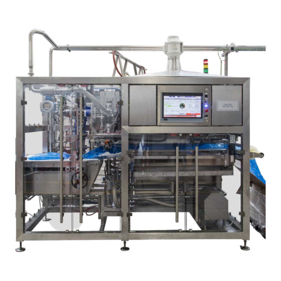
- Page 69 CHAPTER 3 TECHNICAL DATA 3.1.2 MAIN COMPONENTS The ASEPTIC FILLER HS-LA consists of 6 main components: 1. Steam group 2. Electric board 3. Bags strip inlet 4. Sterilization tunnel 5. Filling head 6. Filled bags outlet HS-LA FILLER_IM_E...
- Page 70 THIS PAGE IS INTENTIONALLY LEFT BLANK...
- Page 71 CHAPTER 3 TECHNICAL DATA 3.1.3 OVERALL DIMENSIONS AND WEIGHTS 1411 2600 3089 3310 1331 1411 3065 Layout 01.00.1908-00 TAF 2HM/1” FILLER_IM_E...
- Page 72 THIS PAGE IS INTENTIONALLY LEFT BLANK...
- Page 73 CHAPTER 3 TECHNICAL DATA 3.1.4 WEIGHT AND DIMENSION Weight and dimension Weight 1800 kg Dimension (L x W x H) 3350X1800X2500 3.1.5 PRESSION AND CONSUMPTION Electrical Power Feeding voltage 480 V 60 Hz Installed power 16 Kw Compressed air Pressure 8 Bar Consumption 30 Nmc/h...
- Page 74 CHAPTER 3 TECHNICAL DATA 3.1.7 PRODUCTION TYPE Entering Product Character Max pressure 2-3 Bar Max product temperature 80°C Instantaneous product capacity 500÷15000 l/h Container characters Bags 3-20 l Caps Flat cap Spout Diameter 1” ATTENTION! The quality and performance of the machine are directly proportioned to the quality of the bags used.
- Page 75 The information contained in this section is addressed to the following personnel categories: Mechanical maintenance Electrical maintenance ALFA LAVAL technician INTRODUCTION CAUTION: These instructions shall be made available to the personnel involved in the handling and installation of the machine.
- Page 76 CHAPTER 4 INSTALLATION USE OF PERSONAL PROTECTIVE EQUIPMENT The operators assigned to the charge, the moving and the discharge of the Machine must wear shoes, gloves, working clothes and protective helmet against objects fall. POSITIONING THE MACHINE PARTS - SEE LAYOUT CHAPTER 8 CAUTION: For the installation and the assembly of elements/parts that the personnel cannot reach from the ground, use ladders/cranes in compliance with local...
- Page 77 CHAPTER 4 INSTALLATION CAUTION: Operators must read and understand the “Installation Instructions”, “Commissioning Instructions”, “System Operating Instructions”, and the Operating Instructions of the respective equipment before carrying out any installation work on the system! It is the responsibility of the customer or by the customer appointed responsible for the erection, to ensure that any person involved with the erection of this equipment follows all safety and installation instructions, and local legislation.
- Page 78 CHAPTER 4 INSTALLATION CAUTION: Before starting to handle the machine, make sure that the route to be followed and the intended place of installation are clear of any obstacle. ATTENTION! Raise the machine after verifying the correct positioning of the forks with small lifting movements.
- Page 79 CHAPTER 4 INSTALLATION Tie bends Chain with locked hook CAUTION: Verify the weight capacity of the bends before starting any lifting operations. Use only bends suitable for the weights equipment to move. Sling heavy weight elements to in order to ensure a balanced handling and lifting.
- Page 80 CHAPTER 4 INSTALLATION MACHINE LEVELLING To ensure a smooth, vibration less operation, the machine should be properly leveled. To this effect, the machine is supplied with adjustable legs, in some cases, with fixed legs wich don’t require to be adjusted. CAUTION: Poor levelling of the support frame may prevent the system from working properly.
- Page 81 CHAPTER 4 INSTALLATION 4.5.1 LEVELLING CHECK POINTS Dragging bags rails (Horizontal) HS-LA FILLER_IM_E...
- Page 82 CHAPTER 4 INSTALLATION Filling Head (Vertical) HS-LA FILLER_IM_E...
- Page 83 CHAPTER 4 INSTALLATION MACHINE ASSEMBLING The following paragraph describes the assembly and installation procedures. To orientate the reader see the following drawing: BACK FRONT CAUTION: ● Every pipes connections must be assembled with the proper gaskets. ● Screws, bolts, screw studs, nuts must be assembled with the proper washers.
- Page 84 CHAPTER 4 INSTALLATION 4.6.1 LIGHT TOWER INSTALLATION The machine may reach the customer with the luminous tower A disassembled, for transportation reasons. Restore the light tower A on the electrical panel B as shown in the top picture. HS-LA FILLER_IM_E...
- Page 85 If no specific agreements have been made in writing with Alfa Laval, the user shall be responsible for establishing the features of the power line and earthing conductor up to the terminal board of the machine, as well as selecting appropriate protection devices against short-circuits and contact voltage.
- Page 86 CHAPTER 4 INSTALLATION PRODUCT - CIP - H.W. INLET DN65 CIP RETURN DIN DN40 STEAM INLET - DN25 - PN16 NITROGEN - AIR - INLET 1/2" “A” AIR INLET 1/2" NITROGEN INLET 1/2" “A” Detail of flow connection HS-LA FILLER_IM_E...
- Page 87 CHAPTER 4 INSTALLATION ROTATION OF ELECTRIC MOTORS At the time of wiring, make sure that all motors rotate in the correct direction: CAUTION: To check the direction of rotation, the motors should be operated ONLY by impulses. When performing these operations, follow strictly the safety rules and stay away from any moving part inside the machine.
- Page 88 THIS PAGE IS INTENTIONALLY LEFT BLANK...
- Page 89 CHAPTER 5 INSTRUCTIONS FOR THE OPERATOR INSTRUCTIONS FOR THE OPERATOR ATTENTION! The information contained in this section is addressed to the following personnel categories: Generic operator Mechanical maintenance The operators assigned to the normal work cycle of the machine must wear shoes, gloves and working clothes.
- Page 90 CHAPTER 5 INSTRUCTIONS FOR THE OPERATOR CHECKING BEFORE STARTING CAUTION: Any operation involving the removal of the machine panelling should be performed with the MACHINE STOPPED AND ISOLATED from the power line by putting the lock on the main switch so that nobody can accidentally give power to the machine.
- Page 91 CHAPTER 5 INSTRUCTIONS FOR THE OPERATOR To power on the control board, set the main switch to “1”. The auxiliary devices are enabled (control voltage 24 V AC) by setting the key switch to “1” Open the ball valves on the compressed air circuit feeding the control board, and set pressure to 6 bar by means of the pressure reducer located on the control board.
- Page 92 CHAPTER 5 INSTRUCTIONS FOR THE OPERATOR PUSH BUTTON BOARD DESCRIPTION Following the description of the command buttons of the machine: 24 VDC CONTROL POWER RESET PLRIP ETHERNET 1 2 3 4 5 6 7 8 PEM1 HS-LA FILLER_IM_E...
- Page 93 CHAPTER 5 INSTRUCTIONS FOR THE OPERATOR ITEM NAME DESCRIPTION 24VDC 24 V direct current light CONTROL POWER RE- This button recovers the emergency relay ETHERNET Ethernet connection (only for technical person- nel) EMERGENCY STOP Emergency stop button (see paragraph “2.1.8.2 Emergency buttons”...
- Page 94 CHAPTER 5 INSTRUCTIONS FOR THE OPERATOR STARTING PROCEDURE 5.3.1 OPERATOR’S POSITION To ensure a safe use of the machine during start-up and adjustment operations, we recommend that the operator should stand as indicated in the paragraph”8.1 Layout 01.00.1908-00” 5.3.2 START-UP To carry out initial start-up, proceed as follows: If steam is required, open the manual steam check valve after draining out any condensation (using the drain valve).
- Page 95 CHAPTER 5 INSTRUCTIONS FOR THE OPERATOR 5.3.3 MANUAL BAGS STRIP LOADING 1. Place the bags strip box in the back side of the machine. NOTE: The height of the box does NOT have to be higher than the infeed rollers of the machine, in order to allow a suitable dragging of the bags strip.
- Page 96 CHAPTER 5 INSTRUCTIONS FOR THE OPERATOR 2. Stretch the first bag A of the strip, then lie the first bag A over the infeed rollers C, in order to insert the bag A trailing (first the bottom of the bag A and last the spout B). NOTE: THE BAG HAS TO BE FITTED WITH THE SPOUT B IN FRONT OF THE OPERATOR, IN OR- DER TO PASS THROUGH THE SPOUT GUIDES D AS THE LAST PART OF THE BAG A 3.
- Page 97 CHAPTER 5 INSTRUCTIONS FOR THE OPERATOR 5. Press the button G in order to close the spout clamp. 6. The left spout clamp F moves forward and catches the spout B. HS-LA FILLER_IM_E...
- Page 98 CHAPTER 5 INSTRUCTIONS FOR THE OPERATOR 7. Press “CONFIRM” on the main command touch panel. The first bag is dragged ahead, and the left spout clamp catches the spout of the second bag. 8. The first bag is dragged under the sterilizing tunnel H. 9.
- Page 99 CHAPTER 5 INSTRUCTIONS FOR THE OPERATOR ATTENTION!: NOTE: ONCE THE FIRST BAG IS FED TO THE FILLLING HEAD, MAKE SURE THAT THE BAG IS NOT RUFFLED. OTHERWISE OPEN THE INTERLOCKED DOORS AND STRETCH THE BAG IN ORDER TO HAVE A FLAT SURFACE OF THE BAGS STRIP AS SHOWN IN THE PICTURE. REMEMBER TO CLOSE THE INTERLOCKED DOORS AND TO RESET THE ALARMS IN ORDER TO RESTART THE OPERATION.
- Page 100 CHAPTER 5 INSTRUCTIONS FOR THE OPERATOR ATTENTION! NOTE: THE VERTICAL CYLINDER, PLACED UNDER THE CONVEYOR, WILL LIFT UP AT THE BEGINNING AND AT THE END OF THE FILLING PHASE. AS SHOWN IN THE PICTURE. HS-LA FILLER_IM_E...
- Page 101 CHAPTER 5 INSTRUCTIONS FOR THE OPERATOR 10. Adjust the position of the cutting unit by using the handwheel K, in accordance with the dimension of the first filled bag and the score line between the first and the second filled bag.
- Page 102 CHAPTER 5 INSTRUCTIONS FOR THE OPERATOR 5.3.4 MANUAL BAGS STRIP UNLOADING CAUTION: Any operation involving the removal of the machine paneling should be performed with the MACHINE STOPPED AND ISOLATED from the power line by putting the lock on the main switch so that nobody can accidentally power the machine on.
- Page 103 CHAPTER 5 INSTRUCTIONS FOR THE OPERATOR 5.3.5 LOADING AND UNLOADING DISINFECTANT CAUTION: Any operation involving the disinfectant and chemicals in general, should be performed with extremely care. Operators MUST wear the suitable PPE: gloves and protective visors. Risk of burnings, scalds, corrosion and other injuries caused by possible contact of people and things with corrosive substances.
- Page 104 CHAPTER 5 INSTRUCTIONS FOR THE OPERATOR To load disinfectant in the tank A: 1. Open the door of the machine. The doors are interlocked, so the machine will stop. 2. Open the clamp cap B (diameter 1 1/2”). 3. Fill the tank A with disinfectant. The tank capacity is 20 Lt. Take care to NOT fill the tank A up to the maximum capacity.
- Page 105 CHAPTER 5 INSTRUCTIONS FOR THE OPERATOR OPERATOR PANEL USE - HOME - ATTENTION! Graphics may differ from the represented ones without notice according to the software installed on the equipment. Icons, symbols and arrangement may be lightly different, but the function and meaning of the objects is not changing among different software installations.
- Page 106 CHAPTER 5 INSTRUCTIONS FOR THE OPERATOR F. ACTUAL SPEED. Displays the actual speed, which can differ from the nominal one be- cause of the filling time. G. TOTALIZER. Shows the total number of bags filled. It can not be reset. H.
- Page 107 CHAPTER 5 INSTRUCTIONS FOR THE OPERATOR 5.4.1 PROCESS LAY OUT This page represents the synoptic lay out of the machine and displays the status of each device and instrument. Clicking on each device (motor or valve) or each instrument (temperature, pres- sure, flow, level) opens the related control module page.
- Page 108 CHAPTER 5 INSTRUCTIONS FOR THE OPERATOR 5.4.1.1 DIGITAL CONTROL Clicking on digital device it is possible to see the Digital Control faceplate. For each component, it’s possible: 1. To see the status: The information for the selected utility is displayed: Input logic status indicates the physical status of the utility: Software status indicates the utility status filtered with the set times in the control system.
- Page 109 CHAPTER 5 INSTRUCTIONS FOR THE OPERATOR 5.4.1.2 PNEUMATIC ACTUATOR SETUP Clicking on each valve is possible to see the Device Control faceplate. For each valve, it’s possible: 1. To see the status: The information for the selected utility is displayed: Feedback ON means the utility is controlled;...
- Page 110 CHAPTER 5 INSTRUCTIONS FOR THE OPERATOR 5.4.1.2.1 PNEUMATIC ACTUATOR ADVANCED SETUP Clicking on each valve is possible to see the Device Setup faceplate. For each valve, it’s possible: 1. To set the device: Feedback ON Present: selects if positive feedback is present for the selected utility. Feedback OFF Present: selects if rest position feedback is present for the selected utility.
- Page 111 CHAPTER 5 INSTRUCTIONS FOR THE OPERATOR 5.4.1.3 PROBE SETUP TEMPERATURE Clicking on each instrument it is possible to see the Analogic Control faceplate for the Analog Inputs.. For each instrument, it’s possible: 1.To see: Actual value: is the current read value for the selected utility scaled based on the settings performed in the dedicated page.
- Page 112 CHAPTER 5 INSTRUCTIONS FOR THE OPERATOR 5.4.1.3.1 TEMPERATURE PROBE CALIBRATION Clicking on each instrument field it is possible to see the Analogic Setup faceplate for the Analog Inputs. For each instrument, it’s possible: 1. To see: Current value: is the current value for the selected utility scaled based on the settings performed in the dedicated page.
- Page 113 CHAPTER 5 INSTRUCTIONS FOR THE OPERATOR 5.4.1.4 ANALOG DEVICE CALIBRATION Clicking on each instrument field it is possible to see the Analogic Setup faceplate for the Analog Inputs. For each instrument, it’s possible: 1. To see: Current value: is the current read value for the selected utility scaled based on the settings performed in the dedicated page.
- Page 114 CHAPTER 5 INSTRUCTIONS FOR THE OPERATOR 5.4.1.5 PID CONTROLLER SETUP 5.4.1.5.1 PID CONTROLLER ADVANCED SETUP In this page it’s possible to see/configure the PID parameters. Each parameter is set during the commissioning of the plant. It’s strongly recommended that just a Service Engineer change these parameters.
- Page 115 CHAPTER 5 INSTRUCTIONS FOR THE OPERATOR 5.4.2 MOTION LAY OUT 5.4.2.1 DRIVE CONTROL - MOTOR HS-LA FILLER_IM_E...
- Page 116 CHAPTER 5 INSTRUCTIONS FOR THE OPERATOR 5.4.2.1.1 MOTOR SETUP HS-LA FILLER_IM_E...
- Page 117 CHAPTER 5 INSTRUCTIONS FOR THE OPERATOR 5.4.2.1.2 MOTOR ADVANCED SETUP Clicking on each motor is possible to see the Drive Control faceplate for Motors. For each motor, it’s possible: 1. To see the status: The information for the selected utility is displayed: Feedback Direct indicates that the utility is controlled forward;...
- Page 118 CHAPTER 5 INSTRUCTIONS FOR THE OPERATOR 5.4.2.2 BRUSHLESS MOTOR SETUP The brushless motor setup page displays the same informations of the standard motors but adds features about the encoder data , logic status, jog commands, brake management. 5.4.2.2.1 BRUSHLESS MOTOR ADVANCED SETTINGS The advanced settings include the alarms and maintenance features as the standard motors.
- Page 119 CHAPTER 5 INSTRUCTIONS FOR THE OPERATOR 5.4.3 ASEPTIC TANK HMI REMOTE CONTROL If the machine is fitted with a stand alone aseptic tank, its HMI can be displayed and controlled from remote. 5.4.4 CONVEYOR BELTS LAY OUT If conveying system is present, this page allows to control and setup the single motors and pho- tocells of the system HS-LA FILLER_IM_E...
- Page 120 CHAPTER 5 INSTRUCTIONS FOR THE OPERATOR 5.4.5 ACTIVE MAINTENANCE WARNINGS When a device needs maintenance, it will appear in the list. Maintenance alerts are not alarms, but warnings, so they are not going to stop the filler. 5.4.6 ACTIVE MANUAL COMMANDS All the devices and settings which are not in automatic mode are shown on this screen.
- Page 121 CHAPTER 5 INSTRUCTIONS FOR THE OPERATOR 5.4.7 ACTIVE ALARM All the active alarms are shown A. Clear alarms 5.4.8 DATA RECORDER All critical factors are tracked, displayed and recorded. From the option sub-menu it’s possible to fit the view and export the data. Pens can be hidden by clicking on the color button for easier visualization.
- Page 122 CHAPTER 5 INSTRUCTIONS FOR THE OPERATOR 5.4.9 MOTION RECIPES DATABASE From this database it is possible to choose a motion recipe among the ones tagged as favorites and download it to the PLC. A. Download to PLC 5.4.10 CONTROL PANEL A.
- Page 123 CHAPTER 5 INSTRUCTIONS FOR THE OPERATOR 5.4.10.1 ALARM MANAGEMENT All alarms are listed, spare ones included. In case of multiple machines managed by the filler PLC, the user can select the area and scroll the alarms of that area only. 5.4.10.1.1 ALARM EDIT The alarm edit menu allows the user to set the parameters of each alarm and see the status in-...
- Page 124 CHAPTER 5 INSTRUCTIONS FOR THE OPERATOR 5.4.10.2 HANDSHAKE From this menu it is possible to manage the exchange signals to and from the filler. 5.4.10.2.1 SIGNAL EXCHANGE For each group there are four arrays of signals. Digital INPUT/OUTPUT, analog INPUT/OUTPUT. HS-LA FILLER_IM_E...
- Page 125 CHAPTER 5 INSTRUCTIONS FOR THE OPERATOR 5.4.10.2.1.1 DIGITAL INPUT/OUTPUT SIGNAL SETUP By clicking on each signal, a setup menu is displayed. 5.4.10.2.1.2 ANALOG INPUT/OUTPUT SIGNAL SETUP By clicking on each signal, a setup menu is displayed. HS-LA FILLER_IM_E...
- Page 126 CHAPTER 5 INSTRUCTIONS FOR THE OPERATOR 5.4.10.3 ACTIVE EVENTS All active events are displayed. It is possible to select class and area for ease of consultation. 5.4.10.4 EVENTS HISTORY From this menu it is possible to choose a time period and sort which type of event to be listed. Standard data logging keeps data for 180 days.
- Page 127 CHAPTER 5 INSTRUCTIONS FOR THE OPERATOR 5.4.10.5 LANGUAGE MANAGEMENT Available languages can be choose from this menu. 5.4.10.6 USER MANAGEMENT Existing users are shown, only “A” group users have the rights to make modifications to the other users. HS-LA FILLER_IM_E...
- Page 128 CHAPTER 5 INSTRUCTIONS FOR THE OPERATOR 5.4.10.7 NETWORK Informations about network topology and IP addresses are shown. 5.4.10.8 INFORMATION General informations about Alfa Laval’s facility where the machine has been built. HS-LA FILLER_IM_E...
- Page 129 CHAPTER 5 INSTRUCTIONS FOR THE OPERATOR 5.4.10.9 WINCC DIAGNOSTIC Diagnostic tool for troubleshooting WINCC software issues 5.4.10.10 CALCULATOR Opens the calculator tool. HS-LA FILLER_IM_E...
- Page 130 CHAPTER 5 INSTRUCTIONS FOR THE OPERATOR 5.4.11 USER LOGIN From this screen it is possible to login with different users. Each user has a specific array of ac- cess rights. 5.4.12 RECIPE MENU From this page it’s possible to access to the recipes of each phase of the machine. HS-LA FILLER_IM_E...
- Page 131 Each recipe stored in the database has its dedicated set of parameters which are recalled when it is loaded to the PLC. Most of the parameters are reserved and only Alfa Laval staff is allowed to modify them. Depending on the user logged in, the parameters useful for the tuning and adjustment of the ma- chine are the ones highlighted in the red boxes.
- Page 132 CHAPTER 5 INSTRUCTIONS FOR THE OPERATOR AX105 DECAPPER ANGLE parameters set the center (decapping and recapping) and off-center (filling) positions of the decapper AX103 DECAPPER HEIGHT parameters set the height of the decapper for each handling step HS-LA FILLER_IM_E...
- Page 133 CHAPTER 5 INSTRUCTIONS FOR THE OPERATOR AX106 FILLING VALVE parameters set the height of the filling valve in PRD/CIP/SIP phases AX107 FILLING ROD parameters set the open position of the filling rod in PRD/CIP/SIP phases HS-LA FILLER_IM_E...
- Page 134 CHAPTER 5 INSTRUCTIONS FOR THE OPERATOR VOLUME TARGET parameter is the default volume set when the recipe is loaded and it can be changed in real time during production from the home page PREBATCH [LITERS TO VOLUME TARGET] parameter sets the number of liters to volume target for the filling rod to move to partial opening to improve the accuracy of the dosing.
- Page 135 CHAPTER 5 INSTRUCTIONS FOR THE OPERATOR M1 CONVEYOR BELT parameters set the start/stop cam angles where the conveyor is running NUMBER OF BAGS FOR BAG SEPARATION SHIFT parameter (default is 1) can be changed when filling small/short bags if the bag separation device can not cut the first bag filled. This parameter is for bag count purpose only and is not affecting the functionality of the filler AX150/151 BAG FEEDER parameters set the position of the bag feeder clamps during handling operations according to the size of the bag.
- Page 136 CHAPTER 5 INSTRUCTIONS FOR THE OPERATOR XCV121/122 STEAM PUFFING TIME parameter sets the time [s] of steam puffing after filling to clean the nozzle from drops. If puffing is not required, the parameter can be set to 0 BAG SEPARATION DEVICE POSITION/BAG CONVEYOR POSITION parameters set the value displayed on the home page for the manual setting of the bag separation device.
- Page 137 5.4.12.2 SEQUENCES If the selected sequence is running, this page shows the active steps and the completed ones. A. The selector between “Test and operational” modes is reserved to Alfa Laval Engineers for the status of the machine. HS-LA FILLER_IM_E...
- Page 138 CHAPTER 5 INSTRUCTIONS FOR THE OPERATOR If the selected sequence is not running. This page shows the related interlocks. These turn green if the condition is met or red if it is not. Every individual bar contains the description of the interlock. Start: Allows the cycle to start Stop: Stops the active cycle Reset: Resets the active cycle.
- Page 139 CHAPTER 5 INSTRUCTIONS FOR THE OPERATOR 5.4.12.2.1 RECIPE DATABASE In this page it’s possible to manage the recipes of the selected sequence. Use this button to start creating a new recipe. Use this button to save the data that was changed. Use this button to save the data that was changed to a new recipe.
- Page 140 CHAPTER 5 INSTRUCTIONS FOR THE OPERATOR 5.4.12.2.2 RECIPE SETUP The “A” button opens this actual recipe setup page. 5.4.12.2.2.1 RECIPE PDI SETUP MENU HS-LA FILLER_IM_E...
- Page 141 CHAPTER 5 INSTRUCTIONS FOR THE OPERATOR 5.4.12.2.2.1.1 SINGLE PID SETUP 5.4.12.2.2.2 RECIPE STEP MENU HS-LA FILLER_IM_E...
- Page 142 CHAPTER 5 INSTRUCTIONS FOR THE OPERATOR 5.4.12.2.2.2.1 SINGLE STEP SETUP 5.4.12.2.2.3 PULSE CONFIGURATION Here you can configure the software-enabled valves that you wish to flip. The parameters are as follows: On: sets the time the valve remains controlled. Off: sets the time the valve remains uncontrolled. Delay: sets the delay time in which the valve begins to flip.
- Page 143 CHAPTER 5 INSTRUCTIONS FOR THE OPERATOR 5.4.12.2.3 SEQUENCER REPORT DATABASE This database contains all the saved reports. Filters can be applied like date/time or sequence. A. It is possible to export the data in Microsoft Excel.csv file. 5.4.12.2.3.1 SEQUENCER REPORT HS-LA FILLER_IM_E...
- Page 144 CHAPTER 5 INSTRUCTIONS FOR THE OPERATOR 5.4.12.2.3.1.1 SINGLE REPORT DATA - COUNTS 5.4.12.2.3.1.2 SINGLE REPORT DATA - PID HS-LA FILLER_IM_E...
- Page 145 CHAPTER 5 INSTRUCTIONS FOR THE OPERATOR 5.4.12.2.3.1.3 SINGLE REPORT DATA - STEP 5.4.12.2.3.2 SEQUENCER SINGLE REPORT - TREND From this menu it’s possible to analyze the recorded data related to the selected trend. HS-LA FILLER_IM_E...
- Page 146 CHAPTER 5 INSTRUCTIONS FOR THE OPERATOR 5.4.12.2.3.3 SEQUENCER SINGLE REPORT - EVENTS 5.4.12.2.4 SEQUENCER ONLINE REPORT This page displays the current values of the online report related to the selected sequence. It’s possible to print and export the chart. HS-LA FILLER_IM_E...
- Page 147 CHAPTER 5 INSTRUCTIONS FOR THE OPERATOR 5.4.12.3 MOTION RECIPE DATABASE (ADVANCED) From the database it is possible to create, save, delete, import/export, download/upload the motion recipes. HS-LA FILLER_IM_E...
- Page 148 CHAPTER 5 INSTRUCTIONS FOR THE OPERATOR 5.4.13 USING THE DEVICE SYMBOLS In the layout page, pressing the symbols access the control and settings pages for the object. Pressing the motors accesses the “Motor Status” page described in the apposite section. Pressing the valves accesses the “Valve Status”...
- Page 149 CHAPTER 5 INSTRUCTIONS FOR THE OPERATOR The device is in manual disabled mode and is stopped (Purple Square). The colours are for all displayed devices. Analogue device alarming or analogue value not valid (flashing). Set Point search in progress, the device set point has not been reached (flashing). 5.4.15 DEVICE SYMBOLS Maximum level probe: the status of the maximum level probe is displayed in the upper part of the tank;...
- Page 150 CHAPTER 5 INSTRUCTIONS FOR THE OPERATOR CRITICAL CONTROL POINTS The CCPs of the filler are summarized in the chart. In PRODUCTION cycle if one of the factors drops below the threshold, sterility is considered lost and the machine allows only a CIP cycle. The sterilizing tunnel is kept under a constant flow of sterile air (about 400l/min);...
- Page 151 CHAPTER 5 INSTRUCTIONS FOR THE OPERATOR OPERATIVE PHASES DESCRIPTION 5.6.1 PRODUCTION In production cycle the 310 line - sterile air to the sterilizing tunnel – and the 320 line – air/nitrogen to the filling station are open. All the valves going to steam traps and all the steam valves are closed. XCV310a,b,c,d are closed XCV310L...
- Page 152 CHAPTER 5 INSTRUCTIONS FOR THE OPERATOR During product line cooling, the positive pressure to keep the sterility must be granted by the up- stream equipment, for example pressurized aseptic tank. 5.6.3 CIP cycle consists of three main phases: first drain, cleaning, final drain. In the first drain step, the filling valve AX106 is inserted into the CIP/SIP plate, the AX107 stem is open, XCV301 and XCV308 are closed, XCV303 is open and the CIP return pump P1 is on, so that the product still present in the pipeline can be sent back without flooding the filling station.
- Page 153 CHAPTER 5 INSTRUCTIONS FOR THE OPERATOR ALARMS The process alarms are summarized in the following table: Alarm ID Description SCADA ERROR ON COMMUNICATION ETHERNET IP ELAU SYSTEM ERROR ON COMMUNICATION ETHERNET IP FESTO SYSTEM ERROR ON COMMUNICATION ETHERNET IP REMOTE I/O A1 ERROR ON COMMUNICATION ETHERNET IP PROSOFT ERROR ON COMMUNICATION EHTERNET IP CUSTOMER NETWORK COMMUNICATION NOT OK CONTROLLORE DI MOTION IN ERRORE...
- Page 154 CHAPTER 5 INSTRUCTIONS FOR THE OPERATOR Alarm ID Description TIMEOUT FB YV150 GROUP NOT HIGH DURING AXIS MOVIMENT FORWARD TIMEOUT FB YV150 GROUP NOT HIGH DURING AXIS MOVIMENT REVERSE TIMEOUT FB YV151 GROUP NOT REVERSE DURING AXIS MOVIMENT TIMEOUT FB YV151 GROUP NOT FORWARD DURING AXIS MOVIMENT TIMEOUT FB YV151 CLAMP NOT CLOSE DURING AXIS MOVIMENT FORWARD TIMEOUT FB YV151 CLAMP NOT CLOSE DURING AXIS MOVIMENT REVERSE TIMEOUT FB YV151 GROUP NOT HIGH DURING AXIS MOVIMENT FORWARD...
- Page 155 CHAPTER 5 INSTRUCTIONS FOR THE OPERATOR Alarm ID Description ATTENTION CHANGE TOOLING STERILIZATION TIMER RESET : TE01 UNDER SP STERILIZATION TIMER RESET : TE02 UNDER SP STERILIZATION TIMER RESET : TE05 UNDER SP STERILIZATION TIMER RESET : TE06 UNDER SP STERILIZATION TIMER RESET : TE09 UNDER SP STERILIZATION TIMER RESET : TE10 UNDER SP STERILIZATION TIMER RESET : TE11 UNDER SP...
- Page 156 CHAPTER 5 INSTRUCTIONS FOR THE OPERATOR Alarm ID Description NITROGEN FLOWRATE TOO HIGH HEAD STEAM BARRIER TEMPERATURE LOW HEAD STEAM BARRIER TEMPERATURE TOO LOW HEAD STEAM BARRIER TEMPERATURE HIGH HEAD STEAM BARRIER TEMPERATURE TOO HIGH PEROXIDE FLOWRATE LOW PEROXIDE FLOWRATE TOO LOW PEROXIDE FLOWRATE HIGH PEROXIDE FLOWRATE TOO HIGH Additional alarms:...
- Page 157 CHAPTER 5 INSTRUCTIONS FOR THE OPERATOR GUARDS SAFETY SWITCHES BYPASS ATTENTION!: Use the guards safety switches bypass only for the following operations: - mechanical and/or pneumatic adjustment - maintenance - restoration and replacement of mechanical and/pneumatic parts Any other use of the guards safety switches bypass is forbidden. ATTENTION!: The activation key of the guards safety switches bypass has to be used and kept exclusively by the machine responsible.
- Page 158 CHAPTER 5 INSTRUCTIONS FOR THE OPERATOR - Position 0: the standard working mode. All the movable guards are activated and isolate the operators from the moving parts and from the filling heads. Once that the GUARDS SAFETY SWITCHES BYPASS is in position 0, the machine responsible has to remove the activation key from its seat.
- Page 159 CHAPTER 5 INSTRUCTIONS FOR THE OPERATOR FORMAT CHANGING ATTENTION!: For any operations involving o-ring and gaskets, we remind lubricating these elements with a lubricating grease certified as suitable for use, in the food industry. Unscrew the four bolts A which hold the uncapper plate B to the shaft. and extract it. Extract the uncapper plate B.
- Page 160 CHAPTER 5 INSTRUCTIONS FOR THE OPERATOR Remove the spacer C from the old clamping device. Put some food grade grease in the threads D of the new clamping device and place back the spacer C. HS-LA FILLER_IM_E...
- Page 161 CHAPTER 5 INSTRUCTIONS FOR THE OPERATOR Place the new uncapper E and tighten the four bolts A. HS-LA FILLER_IM_E...
- Page 162 CHAPTER 5 INSTRUCTIONS FOR THE OPERATOR 5.10 EMERGENCY STOP In case of serious danger or failure of the machine, the operation can be immediately halted by pressing the emergency push-buttons. CAUTION: Adequate free space should be provided in front of the machine under any circumstances in order to allow immediate access to the emergency push- button and any start/stop or setting devices.
- Page 163 CHAPTER 5 INSTRUCTIONS FOR THE OPERATOR 5.11 RESTARTING THE MACHINE AFTER IT HAS STOPPED To restart the machine after it has stopped, proceed as follows: Only in the case of an Emergency Stop, reset the red button (turn and lift it). Only in the case of an Emergency Stop, press the blue CONTROL POWER RESET button.
- Page 164 THIS PAGE IS INTENTIONALLY LEFT BLANK...
- Page 165 The steps described are easy to follow and do not require the backup of a qualified technician. However, Alfa Laval Customer Service will be glad to provide the necessary supplements of infor- mation and means to reach the target quickly and effectively.
- Page 166 CHAPTER 6 MAINTENANCE CAUTION: The use, access to internal parts and maintenance of the machine should not be allowed to any personnel not acquainted with the indications of this Manual, which should be made available to as many operators are possible HS-LA FILLER_IM_E...
- Page 167 CHAPTER 6 MAINTENANCE ORDINARY MAINTENANCE OPERATIONS 6.2.1 MAINTENANCE OPERATIONS FOR FILLER’S VALVE BODY. ATTENTION! The valve body has a ceramic coating. The ceramic coating is subject to breaking in the case of crash/shock. It is to be handled with great care. In the case that steam filtering operations are not carried out correctly, the ceramic coating can be scratched or damaged.
- Page 168 RECOMMENDED CLEANING PROCEDURES Introduction The exterior surfaces of the HS-LA filler require a dedicated cleaning procedure. In many cases support structures, mechanical features, conveyors, platforms, and other features of the equip- ment do not have easy access. Those surfaces in the center of the unit will be especially difficult to reach.
- Page 169 We would suggest there would be a physical break between the plant product distribution and the Alfa Laval Filler system. A diverter panel or alternate method should be employed to prevent prod- uct being filled on the adjacent line from being pushed past weak or non- functioning valves into the filler.
- Page 170 CHAPTER 6 MAINTENANCE 6.2.2.2 THE BAG FEEDER AREA Recommended cleaning procedure ● Cleaning may be needed under several conditions: ● At the end of production (generally a daily event) ● At food / beverage product change overs ● During production, generally as a result of a spill, bag break, or other cause there may be a need for a quick “clean-up”...
- Page 171 CHAPTER 6 MAINTENANCE ● As required based on the soils encountered, perform an acid cleaning of the exterior surfaces to aid in removal of mineral scales and potential residual protein, rinse with fresh water. Use caution around soft metals, iron and painted surfaces as acids could cause corrosion of non stainless surfaces.
- Page 172 CHAPTER 6 MAINTENANCE 6.2.2.3 THE BAGS EMPTY OR FILLED Bags should be stored in a clean dry place. Under most conditions there should not be a need for bags to be cleaned. If the integrity of the inside of the bag is sacrificed the bag should be discarded and not used.
- Page 173 CHAPTER 6 MAINTENANCE Recommended cleaning procedure Chemicals If lightly soiled, the bags may be rinsed and dried and returned to production, following the stan- dards set by quality control. Alcohol wipes may be used if the soiling is light enough eliminating the need for water and a drying process.
- Page 174 CHAPTER 6 MAINTENANCE 6.2.2.4 THE HYDROGEN PEROXIDE SPRAYING NOZZLES AND VENTURI DEVICES On top of each peroxide heater there is a nozzle that needs to be cleaned if scale is building up. HS-LA FILLER_IM_E...
- Page 175 CHAPTER 6 MAINTENANCE Recommended cleaning procedure Note: if having difficulties with peroxide nozzles plugging insure a “spray grade” of per- oxide is used for the application. For most supplies of peroxide, when cleaning of the nozzles is necessary a soak cleaning in an acidic solution will dissolve most of the soils present.
- Page 176 CHAPTER 6 MAINTENANCE 6.2.2.5 THE EXTERNAL SIDE OF THE FILLER AND FILLING STATION HS-LA FILLER_IM_E...
- Page 177 CHAPTER 6 MAINTENANCE Recommended cleaning procedure The cleaning of the filler and filling stations is likely performed by manual methods and the process is divided into the following steps: ● Pre rinse with water. ● Perform any necessary lock out tag out requirements and protect water sensitive equipment.
- Page 178 CHAPTER 6 MAINTENANCE Equipment and tools Application of the cleaning solutions may be by bucket and brush, pump up sprayer, or applied with foam applicators, depending on availability within the plant. Detail cleaning requires up close work with small brushes, scrub pads, and similar cleaning tools. Application of rinse waters should be from in-plant water systems using “house”...
- Page 179 CHAPTER 6 MAINTENANCE 6.2.2.6 THE BAG SEPARATOR SYSTEM Recommended cleaning procedure The cleaning of the bag separator system is likely performed by manual methods and the process is divided into the following steps: ● Perform any necessary lock out tag out requirements and protect water sensitive equipment.
- Page 180 CHAPTER 6 MAINTENANCE ● Apply a general purpose cleaner or a chlorinated general purpose cleaner to the sur- faces to be cleaned, detail as necessary. ● Rinse with fresh water. ● Inspect for performance and re-clean as necessary following the above steps. ●...
- Page 181 CHAPTER 6 MAINTENANCE Frequency of cleaning Plant management and quality control should establish a standard as to when cleaning should be performed and the degree of that cleaning. The operators of the equipment should be trained accordingly. Cleaning may be needed under several conditions: ●...
- Page 182 CHAPTER 6 MAINTENANCE ● Rinse with fresh water. ● Inspect for performance and re-clean as necessary following the above steps. ● Apply a potable water rinse. ● As required based on the soils encountered, perform an acid cleaning of the exterior surfaces to aid in removal of mineral scales and potential residual protein, rinse with fresh water.
- Page 183 CHAPTER 6 MAINTENANCE 6.2.2.8 EXTERIORS OF CIP RETURN TANK, ASEPTIC HOLDING TANK, LINES, VALVES, AND OTHER ASSOCIATED STRUCTURES (IF INSTALLED) Recommended cleaning procedure The cleaning of the CIP return tank, aseptic holding tank, lines valves, and other associated struc- tures is likely performed by manual methods and the process is divided into the following steps: ●...
- Page 184 CHAPTER 6 MAINTENANCE Frequency of cleaning Plant management and quality control should establish a standard as to when cleaning should be performed and the degree of that cleaning. The operators of the equipment should be trained accordingly. Cleaning may be needed under several conditions: ●...
- Page 185 CHAPTER 6 MAINTENANCE 6.2.3 MAINTENANCE OPERATIONS FOR CIP / SIP PLATE GASKET Procedure to replace the CIP / SIP gasket ATTENTION! For this operation use protective gloves Use a thin screwdriver to help the removing of the gasket. Manually insert the gasket in position. HS-LA FILLER_IM_E...
- Page 186 CHAPTER 6 MAINTENANCE 6.2.4 AX103 – DECAPPER CLAMP LIFT The zero position of the AX103 servo-drive is all way up, when the plates shown in the pictures match. HS-LA FILLER_IM_E...
- Page 187 CHAPTER 6 MAINTENANCE In order to take the axis in the right position, play with the jog function until the plate reaches the correct position. Once the position is reached, push the e-stop button. HS-LA FILLER_IM_E...
- Page 188 CHAPTER 6 MAINTENANCE Then push the SET POSITION ENCODER button. If the operation is successful, the POSITION field will show 0. Default value is 0. 6.2.5 AX102 AND AX105 – DECAPPER CLAMP ROTATION AND CLOSURE Push the e-stop button, then release the brakes of the AX102 and AX105 servo-motors. HS-LA FILLER_IM_E...
- Page 189 CHAPTER 6 MAINTENANCE HS-LA FILLER_IM_E...
- Page 190 CHAPTER 6 MAINTENANCE Manually rotate the decapper clamp so that the filling valve has room to go downwards freely. Do not over-rotate the decapper and check the upper lever. There must be room for the valve to move freely with no interference with the levers. HS-LA FILLER_IM_E...
- Page 191 CHAPTER 6 MAINTENANCE Reset the motion system by pushing the blue button and clearing the alarms. HS-LA FILLER_IM_E...
- Page 192 CHAPTER 6 MAINTENANCE Operating with the JOG function of the AX103 and AX106 servodrives, take the AX103 axis to a position between 3 and 6. Then lower the AX106 axis to a position as shown in the picture, where the outer side of the valve is about at the middle of the decapper clamp plate height. HS-LA FILLER_IM_E...
- Page 193 CHAPTER 6 MAINTENANCE Push the e-stop and release the AX102 and AX105 brakes. HS-LA FILLER_IM_E...
- Page 194 CHAPTER 6 MAINTENANCE HS-LA FILLER_IM_E...
- Page 195 CHAPTER 6 MAINTENANCE Rotate the AX105 axis until the decapper plate hits the filling valve. While still holding this position, push the SET POSITION ENCODER button of the AX105 axis. If the operation is successful, the POSITION field will show 0. Default value is 0. HS-LA FILLER_IM_E...
- Page 196 CHAPTER 6 MAINTENANCE Once the zero position is set, keep holding the clamp in place and lock the brake of the AX105 axis. Close the clamps by turning the upper lever clockwise. While applying a light force to keep the clamp closed, push the SET ENCODER POSITION button.
- Page 197 CHAPTER 6 MAINTENANCE HS-LA FILLER_IM_E...
- Page 198 CHAPTER 6 MAINTENANCE 6.2.6 AX150 AND AX151 – BAG LOADER CLAMPS Push the e-stop and manually take both clamps all way backwards until they reach the mechanical stop. Then set the position with the SET POSITION ENCODER button. Default value is 0 for both servo-drives.
- Page 199 CHAPTER 6 MAINTENANCE HS-LA FILLER_IM_E...
- Page 200 CHAPTER 6 MAINTENANCE 6.2.7 AX107 – FILLING VALVE STEM Push the e-stop button and release the brake. Push downwards the stem by applying force on top of the actuator and push the SET ENCODER POSITION button, then lock the brake. HS-LA FILLER_IM_E...
- Page 201 CHAPTER 6 MAINTENANCE 6.2.8 AX106 – FILLING VALVE LIFT Take the AX102 and AX105 servo-drives off center in order to let the valve move freely up and down, as described in the AX102/AX105 zero position set section. Playing with the jog function take the AX106 axis to a low position so that it is close to the bottom of the filling head.
- Page 202 HANDBOOK FOR CONVEYOR BELT Le=700 W=1080 TFP modello MNA000166 HANDBOOK FOR BALL VALVE SPIRAX-SARCO model M10S HANDBOOK FOR BUTTERFLY VALVE ALFA LAVAL model LKB-2 HANDBOOK FOR PNEUMATIC MEMBRANE VALVE GEMU model 605 HANDBOOK FOR PNEUMATIC MEMBRANE VALVE GEMU model 650...
- Page 203 Adjustment if necessary. Check tension and regulation. Conveyor chains. Check alignments of automatic feeder EVERY 5.000 BAGS movements. Adjustment if necessary. Check for steam loss. Product valves Alfa Laval. Check membrane. Valves. Check for steam loss. Product valves. Check. Compressed air filter.
- Page 204 CHAPTER 6 MAINTENANCE EVERY 100.000 Replace (or before if necessary). Conveyor chains BAGS See the spare part tables for the specif- Replace (or before if necessary). ic components EVERY 200.000 Replace (or before if necessary). Pneumatic cylinder gaskets. BAGS EVERY 100 STERILIZATIONS Replace.
- Page 205 CHAPTER 6 MAINTENANCE NOT-ORDINARY MAINTENANCE 6.3.1 MOBILE HEAD MOTORS REPLACEMENT The mobile head motors of the filling unit are: E. Rotation uncapper motor F. Lifting uncapper motor. G. Opening/Closing uncapper clamp motor. H. Opening/Closing shutter motor. I. Lifting valve motor. HS-LA FILLER_IM_E...
- Page 206 CHAPTER 6 MAINTENANCE CAUTION: All motors have integrated brakes. Press one of the emergency buttons in order to run the emergency mode and unlock the brakes of the motors. 1. During the maintenance operation, always use supports G (suitable for aseptic environ- ment) for the filling head, in order to avoid damages for the machine and the operators, due to the accidental fall of the filling head.
- Page 207 CHAPTER 6 MAINTENANCE 3. Remove the fixing screws J on both sides in order to free the main plate holder K. CAUTION: If the maintenance requires the filling head removal from the guides L, the use of guide extensions M is strongly suggested in order to avoid damages for the machine and the operators, due to the accidental fall of the filling head.
- Page 208 CHAPTER 6 MAINTENANCE 6.3.1.1 UNCAPPER Slider Plate Tie Rod Uncapper Movement Swivel Head M8x1,25 Uncapper-Reinforced Clamps Group Washer UNI 6592 Ø8 Washer UNI 6592 Ø6 Motor Gear Screw ISO 4014 - M6 x 30 Screw UNI 5739 M08x025 Uncapper Slider Spacer Mounting Pivot Steel Slider TG.15 NRII Screw ISO 4762 - M6 x 12...
- Page 209 CHAPTER 6 MAINTENANCE 6.3.1.2 VALVE HANDLING Cross Support Side Support (RIGHT) Steel Guide TG.15 NRII Side Support (LEFT) Screw UNI 5931 M4x20 Washer UNI 5931 M06x020 Linear Module Stroke 120 Basement plate Joint Shaft Washer UNI 6592 Ø8 Joint D1=16 D2=12 Screw UNI 5739 M08x020 Gear Motor Support Stem Lifting...
- Page 210 CHAPTER 6 MAINTENANCE 6.3.1.3 FILLING VALVE Interchangeable Entrance Valve Body As- O-Ring 3137 sembly Doser Lower Seal Valve Stream Jet Diffuser With Retention Support Seal Valve Bellows Spray Nozzle O-Ring 3181 Nut UNI 5587 M6 Stem Bellows Ø16 O-Ring 2018 O-Ring 3106 Cap for Infeed Manifold Steam Diffuser Guide Stem...
- Page 211 CHAPTER 6 MAINTENANCE 6.3.1.4 STEM LIFTING Slider Plate Support Washer UNI 6592 Ø8 Screw UNI 5739 M08x020 Cylindrical Junction Washer UNI 6592 Ø10 Scrw UNI 5739 M10x025 Steel Slider TG.15 NRII Screw UNI 5931 M04x016 Toothed Rack Screw UNI 5931 M06x030 Motor Gear Motor with Pinion RMT HS-LA FILLER_IM_E...
- Page 212 CHAPTER 6 MAINTENANCE 6.3.2 STERILE FILTER MAINTENANCE Sterile filters of different model and sizes can be installed on the machine depending on their function. The maintenance procedure is the same for all types of sterile filters. Always refer to the attached sterile filter manuals.
- Page 213 CHAPTER 6 MAINTENANCE 6.3.3 DISINFECTANT TANK MAINTENANCE Unscrew the 4 screws A and remove dosing container B. Unscrew the 3 screws C located below dosing container B and remove glass D. Replace the two gaskets E, placed above and below glass D. Reassemble in reverse order.
- Page 214 CHAPTER 6 MAINTENANCE 6.3.4 BATTERIES -CPU Electronic card. replace every 2 years. -Video terminal. Replace every 2 years. Note: If the working atmosphere of the machine is not optimum (condensating humidity, dust etc..) then a preventive maintenance is recommended by halving the indicated values. If the compressed air fed to the machine has a lot of condensation, check at each production the efficiency of the reduction system’s automatic draining For machines which work only seasonally (eg.
- Page 215 CHAPTER 6 MAINTENANCE CLEANING At the end of the production cycle you must carry out the washing of the whole machine with water or with neutral detergent, do not use any solvent, such as alcohol, gasoline, etc. CAUTION: Cleaning must be carried out with the disconnected machine from energy sources (electrical supplies) The workers assigned to the maintenance and cleaning must wear work clothes, shoes anti-slip sole, gloves, goggles/protective visor.
- Page 216 CHAPTER 6 MAINTENANCE LIST OF MAINTENANCE CARRIED OUT HOURS WORKED TYPE OF INTERVENTION SIGNATURE OF DATE OR BAGS FILLED MAINTENANCE ENGINEER HS-LA FILLER_IM_E...
- Page 217 CHAPTER 7 SPARE PARTS SUGGESTED SPARE PARTS Introduction In order to limit the number of shutdowns in production, servicing, and resetting the operations in the machine, it is advisable to keep a series of suggested spare parts available for elements that are subject to greater stress and therefore to greater wear.
- Page 218 CHAPTER 7 SPARE PARTS Qty. Qty. Pos. Description Code Installed Suggested Uncapper assembly - reinforced clamps 04-02-101-00 Bushing 0315-103599 Clamp bushing 04-02-0062 Bushing 0315-101702 Clamp plain washer 04-02-0067 Clamp support 04-02-0095 Bushing 0315-101748 Aseptic filling head assembly - 70-51-001-01 Sight glass gasket DN65 0306-103116 Sight glass DN65 0315-103527...
- Page 219 CHAPTER 7 SPARE PARTS Qty. Qty. Pos. Description Code Installed Suggested Uncapper assembly - 70-56-001-01 Swivel head M8x1,25 0311-100985 Gasket OR-2250 63,22x1,78 OR-2250 Plate 0301-103036 Valve handling - 70-57-002-02 Joint 04-01-0055 Joint 40-08-040 Linear module 0316-103612 Steam lifting - 70-57-001-01 Plate 0301-103036 Loader group - 70-55-001-01...
- Page 220 CHAPTER 7 SPARE PARTS Qty. Qty. Pos. Description Code Installed Suggested Washing plate group assembly - 70-58-001-02 Kit for Cylinder 0306-103687 Kit for Cylinder 0306-103686 Compact cylinder 0306-103684 Gasket OR-147 OR-147 Gasket OR 274x6 0350-103876 Gasket OR 250x6 0350-103875 Kit for Cylinder 0306-103685 Clamp support assembly - 70-68-001-01 40-01-060...
- Page 221 CHAPTER 7 SPARE PARTS Qty. Qty. Pos. Description Code Installed Suggested Sterilized air heater assembly - 70-66-022-01 Cartridge Heater 0316-103944 Suction ejector assembly - 21-01-090-00 Gasket OR-2062 OR-2062 Dispenser tank - 21-06-338 Levels insulating 21-00-026-1 OR 2021 Viton gasket OR-2021 OR 3075 Viton gasket OR-3075 OR 6275-S Viton gasket...
- Page 222 CHAPTER 7 SPARE PARTS Qty. Qty. Pos. Description Code Installed Suggested Safety valve 0309-103439 Steam trap 0313-103577 Kit for butterfly valve DN40 9611923077 Electro-pneumatics Monostable solenoid valve 0311-103432 Bistable solenoid valve 0311-103434 Multiples electrical outlet 0317-103105 Cable PLC-DB4 0317-103139 Cables DB4-DB4/motor 3m 0317-103113 Triple stage motor without brake 0317-103138...
- Page 223 CHAPTER 7 SPARE PARTS Qty. Qty. Pos. Description Code Installed Suggested Combibox Gray rectangular belt with rubber 0390-100048 inserts Chain guide for carton transport combi 0390-100055 Chain joint 10B-1 5/8" INOX 0390-100056 Roller chain 10B-1 5/8" INOX 0390-100057 Toothed belt 25 AT10 0390-100004 HS-LA FILLER_IM_E...
- Page 224 CHAPTER 7 SPARE PARTS SPARE PARTS TABLE 7.2.1 INTRODUCTION Spare parts tables have a double purpose, i.e. to order the single items, and to ease service personnel’s task when tracing the item inside the plant. 7.2.2 DESCRIPTION OF CONTENTS OF SPARE PART TABLES Each group is divided into two tables: the drawn table, showing the spare parts and the relevant position by means of numerical references;...
- Page 225 CHAPTER 7 SPARE PARTS 7.2.3 HOW TO INTERPRET THE SPARE PART TABLES Methodology If you want to know the full details of a single item, in order to fill in the enquiry form included in subject "7.3 HOW TO ORDER SPARE PARTS ", PARAGRAPH "FROM TO ORDER SPARE PARTS", you must identify the drawing in which the requested component is indicated and take note of the necessary details from the drawing list for the compilation of the request.
- Page 226 CHAPTER 7 SPARE PARTS 7.2.4 FILLING VALVE ASSEMBLY - 70-57-003-02 HS-LA FILLER_IM_E...
- Page 227 CHAPTER 7 SPARE PARTS 7.2.4 FILLING VALVE ASSEMBLY - 70-57-003-02 Ref. Our Code Description U.M. 01-10-0266-02 Exchangeable entrance valve body assembly 01-10-1062 Lower seal 01-10-1120-01 Folding seal valve support OR-3181 Gasket OR-3181 0315-103882 Folding for stem ø16 OR-3106 Gasket OR-3106 01-10-1135-01 Stem guide pin 01-13-397...
- Page 228 CHAPTER 7 SPARE PARTS 7.2.5 VALVE STEAM DIFFUSER ASSEMBLY - 70-57-005-01 HS-LA FILLER_IM_E...
- Page 229 CHAPTER 7 SPARE PARTS 7.2.5 VALVE STEAM DIFFUSER ASSEMBLY - 70-57-005-01 Ref. Our Code Description U.M. 40-03-017 Filling valve steam jet diffuser HS 2015 01-10-313-01 Filling valve steam jet diffuser attack 01-10-1175 HS steam jet body plug 0325-102506 Screw TE M5 x 20 OR-108 Gasket OR-108 OR-3143...
- Page 230 CHAPTER 7 SPARE PARTS 7.2.6 UNCAPPER MOVEMENT ASSEMBLY - 04-02-0022-01 HS-LA FILLER_IM_E...
- Page 231 CHAPTER 7 SPARE PARTS 7.2.6 UNCAPPER MOVEMENT ASSEMBLY - 04-02-0022-01 Ref. Our Code Description U.M. 04-02-0023 Uncapper support 0304-100060 Seal ring 04-02-0029 Uncapper hub 0301-100035 Bearing D.=30 04-02-0030 Uncapper spacer 04-02-0039 Uncapper spindle 04-02-0027 Lower lever 0301-103031 Locking collar M30x1,5 0315-101704 Bushing 0303-103024...
- Page 232 CHAPTER 7 SPARE PARTS 7.2.7 UNCAPPER ASSEMBLY - SMURFIT SCREWCAP - 04-02-101-00 9 15 HS-LA FILLER_IM_E...
- Page 233 CHAPTER 7 SPARE PARTS UNCAPPER ASSEMBLY - FLAT CAP 7.2.7 - 04-02-101-00 Ref. Our Code Description U.M. 04-02-098 Clamp body 04-02-0099 Left clamp 04-02-0112-01 Left clamp (Smurfit) 04-02-0100 Right clamp 04-02-0111-01 Right clamp (Smurfit) 04-02-0073 Uncapper clamp lower lever 0315-103599 Bushing 04-02-097 Grub screw M8x50...
- Page 234 CHAPTER 7 SPARE PARTS 7.2.8 ASEPTIC FILLING HEAD ASSEMBLY - 70-51-001-01 30 32 31 HS-LA FILLER_IM_E...
- Page 235 CHAPTER 7 SPARE PARTS 7.2.8 ASEPTIC FILLING HEAD ASSEMBLY - 70-51-001-01 Ref. Our Code Description U.M. 40-13-015-01 Finished filling chamber base assembly 40-01-050 Bulkhead pivot support new 40-01-049 Bulkhead 40-04-006 Bulkhead 40-01-051 Washing plate invitation 0306-103116 Sight glass gasket DN65 0315-103527 Sight glass DN65 40-03-015...
- Page 236 CHAPTER 7 SPARE PARTS 7.2.8 ASEPTIC FILLING HEAD ASSEMBLY - 70-51-001-01 Ref. Our Code Description U.M. 08-02-0031 Condensed suction pipe D.8 21-00-120 Hexagonal nut M8x1 0307-103075 Junction with sleeve ø1-8 OR-2062 Gasket OR-2062 40-08-014 Diffuser feeding manifold 70-51-002-00 Tap presence 01-10-037 Male hinge 01-10-038...
- Page 237 THIS PAGE IS INTENTIONALLY LEFT BLANK...
- Page 238 CHAPTER 7 SPARE PARTS 7.2.9 PRESENCE CAP - 70-51-002-00 HS-LA FILLER_IM_E...
- Page 239 CHAPTER 7 SPARE PARTS 7.2.9 PRESENCE CAP - 70-51-002-00 Ref. Our Code Description U.M. 04-02-0085 Sensor support 0310-103417 Proximity switch 21-00-120 0325-101756 Washer 0325-102506 Screw 01-10-227 Sensor lever 01-10-088 Spring connection for sensor lever 01-10-107 Spring 01-10-086-1 Lever hub 0315-101702 Bushing OR-2062 Gasket OR-2062...
- Page 240 CHAPTER 7 SPARE PARTS 7.2.10 UNCAPPER ASSEMBLY - 70-56-001-01 37 16 19 19 9 18 22 13 36 18 HS-LA FILLER_IM_E...
- Page 241 CHAPTER 7 SPARE PARTS 7.2.10 UNCAPPER ASSEMBLY - 70-56-001-01 Ref. Our Code Description U.M. Sliding pieces plate 04-02-0026-00 Uncapper movement 04-02-0022-01 Uncapper assembly - Reinforced clamp 04-02-0117 Plain washer Ø6 0325-101810 Washer T.E. M6 x 30 0325-103065 Sliding piece 0301-103036 New gear motor support 08-02-0024-02 Screw T.E.
- Page 242 CHAPTER 7 SPARE PARTS 7.2.10 UNCAPPER ASSEMBLY - 70-56-001-01 Ref. Our Code Description U.M. Uncapper slider spacer 40-02-020-00 Long uncapper tie-beam 40-01-041-00 Motor gear with pinion 0318-103211 Guide 0301-103037 HS-LA FILLER_IM_E...
- Page 243 CHAPTER 7 SPARE PARTS 7.2.11 VALVE HANDLING ASSEMBLY - 70-57-002-02 HS-LA FILLER_IM_E...
- Page 244 THIS PAGE IS INTENTIONALLY LEFT BLANK...
- Page 245 CHAPTER 7 SPARE PARTS 7.2.11 VALVE HANDLING ASSEMBLY - 70-57-002-02 Ref. Our Code Description U.M. 04-02-0015-01 Cross support 0301-103037 Guide 0325-103043 Screw M4x20 0316-103612 Linear module strike=120 04-02-0043-01 Junction shaft 04-01-055 Joint 0318-101181 Motor gear 0325-101756 Plain washer Ø5 0325-103074 Screw T.E.
- Page 246 CHAPTER 7 SPARE PARTS 7.2.12 STEM LIFTING ASSEMBLY - 70-57-001-01 HS-LA FILLER_IM_E...
- Page 247 CHAPTER 7 SPARE PARTS 7.2.12 STEM LIFTING ASSEMBLY - 70-57-001-01 Ref. Our Code Description U.M. 04-02-0013-00 Plate for sliding pieces 04-02-0016-00 Spindle support 0325-101437 Plain washer Ø8 0325-101444 Screw T.E. M08x020 04-02-0057-00 Cylinder connection 0325-101518 Plain washer Ø10 0325-101624 Screw T.E. M10x025 0301-103036 Sliding piece 0325-103042...
- Page 248 CHAPTER 7 SPARE PARTS 7.2.13 LOADER GROUP ASSEMBLY - 70-55-001-01 HS-LA FILLER_IM_E...
- Page 249 CHAPTER 7 SPARE PARTS 7.2.13 LOADER GROUP ASSEMBLY - 70-55-001-01 Ref. Our Code Description U.M. 0316-103959 Linear module strike=1360 70-61-001-02 Bag feeder clamp 0317-103138 Motor 40-13-036 Shaft cover 04-02-0108 Bag feeder support 0315-103916 Cables holder chain 70-61-002-01 Bag feeder clamp 150 HS-LA FILLER_IM_E...
- Page 250 THIS PAGE IS INTENTIONALLY LEFT BLANK...
- Page 251 CHAPTER 7 SPARE PARTS 7.2.14 BAG FEEDER CLAMP ASSEMBLY - 70-61-001-02 26 28 35 28 27 28 HS-LA FILLER_IM_E...
- Page 252 THIS PAGE IS INTENTIONALLY LEFT BLANK...
- Page 253 CHAPTER 7 SPARE PARTS 7.2.14 BAG FEEDER CLAMP ASSEMBLY - 70-61-001-02 Ref. Our Code Description U.M. 40-01-038 Clamp supporting plate 40-01-025 Cylinder fixing support 0325-103217 Screw T.C.E.I. M08x012 0311-103638 Compact cylinder 0325-101669 Screw T.C.E.I. M06x020 40-01-027-01 Sliding block support 40-01-014-01 Top plate hs clamp 40-01-026 Cylinder support...
- Page 254 CHAPTER 7 SPARE PARTS 7.2.14 BAG FEEDER CLAMP ASSEMBLY - 70-61-001-02 Ref. Our Code Description U.M. 40-01-127 Plate 0310-103746 Magnetic sensor HS-LA FILLER_IM_E...
- Page 255 CHAPTER 7 SPARE PARTS 7.2.15 BAG FEEDER CLAMP 150 ASSEMBLY - 70-61-002-00 HS-LA FILLER_IM_E...
- Page 256 THIS PAGE IS INTENTIONALLY LEFT BLANK...
- Page 257 CHAPTER 7 SPARE PARTS 7.2.15 BAG FEEDER CLAMP 150 ASSEMBLY - 70-61-002-00 Ref. Our Code Description U.M. 40-01-027-01 Sliding block support 0301-103035 Bearing 40-01-016-01 Clamp finger 0315-103879 Bushing 40-01-017 HS clamp connecting rod 40-01-018 Clamp joint 40-08-003 Centering pin 0302-100000 External seeger Ø6 0325-102302 Screw T.C.E.I.
- Page 258 CHAPTER 7 SPARE PARTS 7.2.15 BAG FEEDER CLAMP 150 ASSEMBLY - 70-61-002-00 Ref. Our Code Description U.M. 40-08-037 Reference pin 0310-103746 Magnetic sensor HS-LA FILLER_IM_E...
- Page 259 THIS PAGE IS INTENTIONALLY LEFT BLANK...
- Page 260 CHAPTER 7 SPARE PARTS 7.2.16 FLAT UNCAPPER KIT - 70-61-004 A-A ( 1 : 2 ) HS-LA FILLER_IM_E...
- Page 261 CHAPTER 7 SPARE PARTS 7.2.16 FLAT UNCAPPER KIT - 70-61-004 Ref. Our Code Description U.M. 08-07-0058-01 Left BF Clamp 08-07-0059-01 Right BF Clamp 04-02-101-00 Uncapper groum Smurfit 70-57-005-01 Valve steam jet diffuser with without retention CM15-077-26 Single steam gasket CM15-077-27 Single steam gasket nozzle 0306-103389 Seal ATP akSP 27X19,7X3,6...
- Page 262 CHAPTER 7 SPARE PARTS 7.2.17 WASHING PLATE GROUP ASSEMBLY - 70-58-001-02 HS-LA FILLER_IM_E...
- Page 263 CHAPTER 7 SPARE PARTS 7.2.17 WASHING PLATE GROUP ASSEMBLY - 70-58-001-02 Ref. Our Code Description U.M. 40-13-001-01 Washing plate frame 40-01-036-00 Polyethylene plate 40-01-037-00 Washing group support plate 0325-101810 Plain washer Ø6 0325-103065 Screw T.E. M06x030 0311-103643 Flanged junction 40-13-002-00 Welded plates 0325-101441 Screw T.C.E.I.
- Page 264 CHAPTER 7 SPARE PARTS 7.2.17 WASHING PLATE GROUP ASSEMBLY - 70-58-001-02 Ref. Our Code Description U.M. 70-58-004-01 Washing plate pointer 21-00-218 Pipe holder support L=120 40-13-043 Drain plate 40-01-090 Drain plate 0310-103746 Magnetic sensor 21-00-305 Pipe holder support Ø12 L=30 0307-100189 Pipe holder DN32 0307-100190...
- Page 265 THIS PAGE IS INTENTIONALLY LEFT BLANK...
- Page 266 CHAPTER 7 SPARE PARTS 7.2.18 CLAMP SUPPORT ASSEMBLY - 70-68-001-01 HS-LA FILLER_IM_E...
- Page 267 CHAPTER 7 SPARE PARTS 7.2.18 CLAMP SUPPORT ASSEMBLY - 70-68-001-01 Ref. Our Code Description U.M. 40-13-040-01 Rotating assembly 40-01-060 40-08-012 Spacer 0315-103908 Bushing 40-05-001 Shaft 0302-100005 External seeger Ø14 0311-103672 Tie rod M10x1,25 0311-103669 Tie rod M10x1,25 0311-103671 Compact cylinder 0311-103670 Compact cylinder 0315-103907...
- Page 268 CHAPTER 7 SPARE PARTS 7.2.19 CUTTER ASSEMBLY - 70-60-001-02 HS-LA FILLER_IM_E...
- Page 269 CHAPTER 7 SPARE PARTS 7.2.19 CUTTER ASSEMBLY - 70-60-001-02 Ref. Our Code Description U.M. 40-13-037 Crossbar 40-02-033 Side plate 0325-101437 Plain washer Ø8 0325-101514 Screw T.E. M06x016 0311-103006 Fork M10x1,25 40-13-038 Pad support 40-11-008 Rubber pad 40-02-034 Pad support sheet metal 40-13-049 Cutter blade 0311-103676...
- Page 270 CHAPTER 7 SPARE PARTS 7.2.20 TANK ASSEMBLY - 21-06-335-01 HS-LA FILLER_IM_E...
- Page 271 CHAPTER 7 SPARE PARTS 7.2.20 TANK ASSEMBLY - 21-06-335-01 Ref. Our Code Description U.M. 04-08-0001-01 Tank group 0307-100097 Nipple 0307-100129 Junction 0309-100447 Manual ball valve 40-01-094 Process pump bracket support 0314-103021 Membrane pneumatic pump 0307-101663 Nipple 0307-100106 Junction 0307-100098 Nipple 21-00-042 Juntion 0307-103301...
- Page 272 CHAPTER 7 SPARE PARTS 7.2.21 VENTURI GROUP ASSEMBLY - 70-66-010-01 HS-LA FILLER_IM_E...
- Page 273 CHAPTER 7 SPARE PARTS 7.2.21 VENTURI GROUP ASSEMBLY - 70-66-010-01 Ref. Our Code Description U.M. 70-66-008-00 Injector body 70-66-009-01 Insulator 70-66-007-00 External strip 0325-101670 Screw T.C.E.I. M06x035 70-66-006-00 Junction 70-66-005-00 Sleeve for adjustement 70-66-002-00 Venturi meter body 70-66-004-00 Venturi meter body connection 70-66-001-00 Venturi group spacer OR-2050...
- Page 274 CHAPTER 7 SPARE PARTS 7.2.22 STERILIZED AIR HEATER ASSEMBLY - 70-66-022-01 HS-LA FILLER_IM_E...
- Page 275 CHAPTER 7 SPARE PARTS 7.2.22 STERILIZED AIR HEATER ASSEMBLY - 70-66-022-01 Ref. Our Code Description U.M. 70-66-027 Sterilized air heater group 0316-103944 Cartridge Heater HS-LA FILLER_IM_E...
- Page 276 CHAPTER 7 SPARE PARTS 7.2.23 EJECTION STEAM BARRIER PIPING ASSEMBLY - 70-69-026-01 HS-LA FILLER_IM_E...
- Page 277 CHAPTER 7 SPARE PARTS 7.2.23 EJECTION STEAM BARRIER PIPING ASSEMBLY - 70-69-026-01 Ref. Our Code Description U.M. 0307-100114 Welding male part 0307-103180 Clamp 0319-100756 Pipe Ø12 0307-103180 Clamp ferrule BS 4825 Inch 1-2 0307-102199 Clamp gasket 0307-102198 Clamp claw 0309-101039 Pneumatic membrane valve 0307-100122 Socket...
- Page 278 CHAPTER 7 SPARE PARTS 7.2.24 SUCTION EJECTOR ASSEMBLY - 21-01-090-00 HS-LA FILLER_IM_E...
- Page 279 CHAPTER 7 SPARE PARTS 7.2.24 SUCTION EJECTOR ASSEMBLY - 21-01-090-00 Ref. Our Code Description U.M. 21-01-083-00 Ejector body 21-01-089-00 Ejector juntion OR-2062 Gasket OR-2062 21-01-018-00 Ejector hub 21-01-084-00 Ejector nozzle HS-LA FILLER_IM_E...
- Page 280 CHAPTER 7 SPARE PARTS 7.2.25 DISPENSER TANK - 21-06-338 H2O2 TO ATOMIZER 2 3 4 PART. A 9 C6 HS-LA FILLER_IM_E...
- Page 281 CHAPTER 7 SPARE PARTS 7.2.25 DISPENSER TANK - 21-06-338 Ref. Our Code Description U.M. 21-00-001 Union ø1/4" 21-00-003 Nut ø1/8" and ø1/4" 21-00-026-1 Levels insulating 21-06-027 Disinfectant suction pipe 21-06-004 Support for dosing 21-06-026 Reinforcement ring 21-06-014-02 Upper flange 21-06-015-01 Lower flange 21-06-003 Tie rod...
- Page 282 CHAPTER 7 SPARE PARTS 7.2.26 VENTURI GROUP ASSEMBLY - 70-66-010-01 HS-LA FILLER_IM_E...
- Page 283 CHAPTER 7 SPARE PARTS 7.2.26 VENTURI GROUP ASSEMBLY - 70-66-010-01 Ref. Our Code Description U.M. 21-01-090 Ejector assembly 0307-100114 Welding male 0309-101039 Membrane valve 40-08-14 Diffuser feeding manifold 0307-100096 Nipple 0307-100129 Union 0307-103180 Clamp 0307-102199 Clamp gasket 0307-102198 Clamp 21-00-175 Extension 0307-100105 Reduction...
- Page 284 7.3.1 USE OF THE CATALOGUE In order to keep the quality and operation characteristics of Alfa Laval machines intact, only origi- nal spare parts must be used. The use of spare parts that are not original means the immediate withdrawal of the warranty.
- Page 285 CHAPTER 7 SPARE PARTS 7.3.3 CARD FOR SPARE PARTS ORDERING SPARE PARTS ORDERING CARD Client Machine model Serial Number Order date Table No. Pos. No. Code Description HS-LA FILLER_IM_E...
- Page 286 THIS PAGE IS INTENTIONALLY LEFT BLANK...
- Page 287 CHAPTER 8 LAY OUT - P&ID - ELECTRICAL DIAGRAM LAYOUT - FLOW SHEET - ELECTRIC AND PNEUMATIC DIAGRAM LAYOUT 01.00.1908-00 1411 PRODUCT - CIP - H.W. INLET DN65 CIP RETURN DIN DN40 STEAM INLET - DN25 - PN16 NITROGEN - AIR - INLET 1/2" DRAIN DISINFECTANT DRAIN 2600...
- Page 288 THIS PAGE IS INTENTIONALLY LEFT BLANK...
- Page 289 CHAPTER 8 LAY OUT - P&ID - ELECTRICAL DIAGRAM P&ID 05.04.1330-02 HS-LA FILLER_IM_E...
- Page 290 THIS PAGE IS INTENTIONALLY LEFT BLANK...
- Page 291 CHAPTER 8 LAY OUT - P&ID - ELECTRICAL DIAGRAM HS-LA FILLER_IM_E...
- Page 292 THIS PAGE IS INTENTIONALLY LEFT BLANK...
- Page 293 CHAPTER 8 LAY OUT - P&ID - ELECTRICAL DIAGRAM HS-LA FILLER_IM_E...
- Page 294 THIS PAGE IS INTENTIONALLY LEFT BLANK...
- Page 295 CHAPTER 8 LAY OUT - P&ID - ELECTRICAL DIAGRAM HS-LA FILLER_IM_E...
- Page 296 THIS PAGE IS INTENTIONALLY LEFT BLANK...
- Page 297 CHAPTER 8 LAY OUT - P&ID - ELECTRICAL DIAGRAM HS-LA FILLER_IM_E...
- Page 298 THIS PAGE IS INTENTIONALLY LEFT BLANK...
- Page 299 CHAPTER 8 LAY OUT - P&ID - ELECTRICAL DIAGRAM HS-LA FILLER_IM_E...
- Page 300 THIS PAGE IS INTENTIONALLY LEFT BLANK...
- Page 301 CHAPTER 8 LAY OUT - P&ID - ELECTRICAL DIAGRAM HS-LA FILLER_IM_E...
- Page 302 THIS PAGE IS INTENTIONALLY LEFT BLANK...
- Page 303 CHAPTER 8 LAY OUT - P&ID - ELECTRICAL DIAGRAM 8.2.1 LIST OF COMPONENTS For a better comprehension of the machine, we list below the numerical references, the description and the make of each component installed on the machine. Each reference (first column of the P&ID No.
- Page 304 CHAPTER 8 LAY OUT - P&ID - ELECTRICAL DIAGRAM 0313-103001 Valve DN1/2” 0313-103001 Valve DN1/2” 0314-103021 Membrane pump 9613394931 Centrifugal pump 0311-103653 Service unit flow tunnel 0311-103652 Service unit air 0311-103651 Service unit nitrogen 0313-103190 Pressure regulator DN 1/2” 1,4 - 4 bar 0313-103190 Pressure regulator DN 1/2”...
- Page 305 CHAPTER 8 LAY OUT - P&ID - ELECTRICAL DIAGRAM 0313-103577 Steam trap Ø1/2” 310b 0313-103577 Steam trap Ø1/2” 310a 0313-103577 Steam trap Ø1/2” 320b 0313-103577 Steam trap Ø1/2” 320a 0313-103577 Steam trap Ø1/2” Disinfectant tank 20L 21-06-338 Tank dispenser 0310-103428 Temperature probe PT100 Ø3x24mm - 1/8”...
- Page 306 CHAPTER 8 LAY OUT - P&ID - ELECTRICAL DIAGRAM 310b 0309-101039 Membrane pneumatic valve DN8 320a 0309-101039 Membrane pneumatic valve DN8 320b 0309-101039 Membrane pneumatic valve DN8 0309-103958 Membrane pneumatic valve DN15 0309-103227 Membrane pneumatic valve DN15 HS-LA FILLER_IM_E...
- Page 307 The rated values for voltage and frequency in the electric input system should be those indicated in the contract and appearing on the machine equipment. If not otherwise indicated in the contract between the Customer and Alfa Laval, the electric system shall be prepared in accordance with International Regulations IEC 204.
- Page 308 THIS PAGE IS INTENTIONALLY LEFT BLANK...
- Page 309 14. HANDBOOK FOR SIGNAL CONDITIONING INSTRUMENT VEGA model VEGATOR 132 15. HANDBOOK FOR PRESSURE SWITCHES DANFOSS model ISG231-031 16. HANDBOOK FOR CENTRIFUGAL PUMP ALFA LAVAL model SOLID C-01 17. HANDBOOK FOR ELECTRIC MOTORS WEG 18. HANDBOOK FOR MEMBRANE PNEUMATIC PUMP SMC model PB1013 19.
- Page 310 CHAPTER 9 COMPONENTS AND CERTIFICATES 20. HANDBOOK FOR GENERATION WITTENSTEIN model LP 21. HANDBOOK FOR BALL RAIL SYSTEMS REXROT 22. HANDBOOK FOR BOURDON TUBE PRESSURE GAUGE model MGS18 HS-LA FILLER_IM_E...
- Page 311 CHAPTER 10 UPDATINGS UPDATINGS 10.1 MANUAL UPDATINGS Introduction: If after the reception of this publication, the machine will be submitted to changes, we will send you an updated copy of the CD. NOTE! We will change the VERSION number placed at the bottom of first page of the publication.
- Page 312 THIS PAGE IS INTENTIONALLY LEFT BLANK...
Need help?
Do you have a question about the HS-LA FILLER and is the answer not in the manual?
Questions and answers