Advertisement
Description
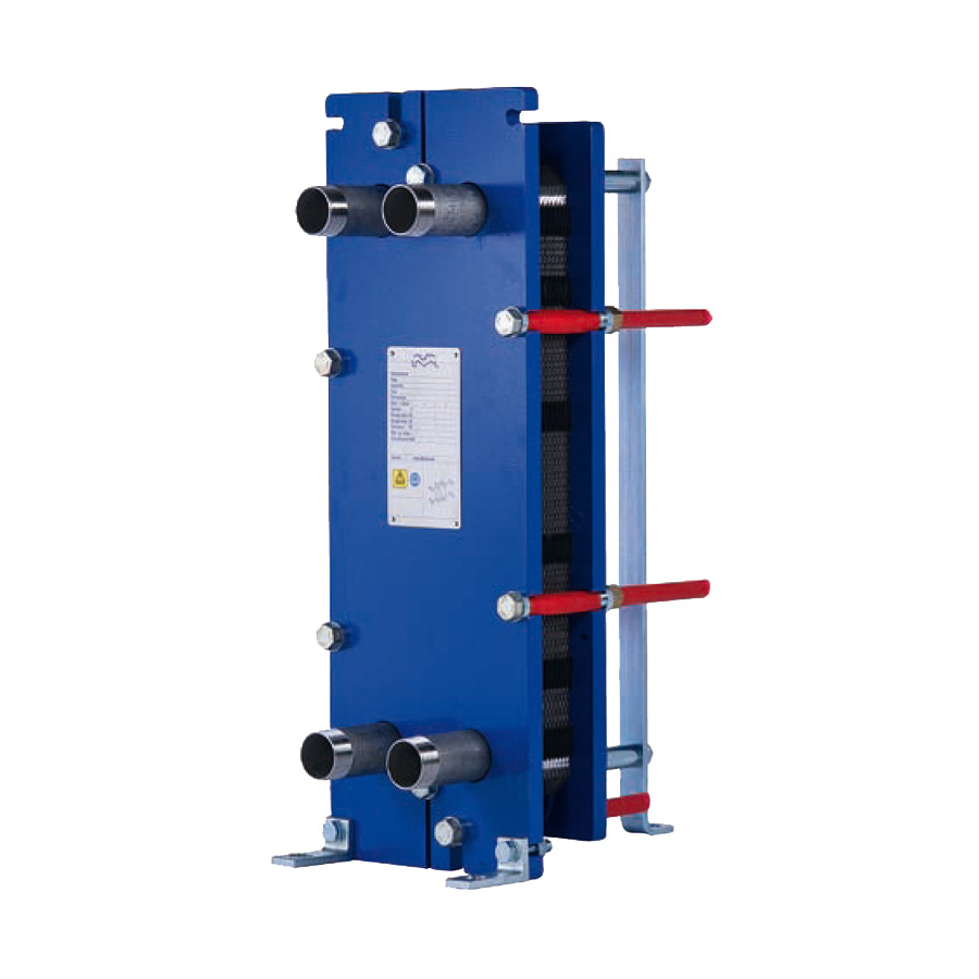
Main components
Frame plate
Tightening bolts
Press the channel
plates together.
Connections
Holes through the frame plate,
permitting the media to enter into
the heat exchanger.
Threaded studs around the
holes secure the pipes to the ap-
paratus. Metallic or rubber-type
linings may be used to protect
the holes against corrosion.
Connections can also be pipes
for welding or threaded.
Pipe connections
Plate Heat Exchanger
Description
Carrying bar
Carries the channel plates
and the pressure plate.
Channel plates
Heat is transferred from one
medium to the other through
the thin channel plates.
The number of plates deter-
mines the total heat transfer
surface.
Protective sheets
In the USA mandatory, in
other countries optional.
Bolt
protection
Guiding bar
Keeps the channel
plates in line at their
lower end.
Pressure plate
Moveable steel plate. In some cases
pipes may be connected to the pres-
sure plate.
English
Support
column
EN
1
Advertisement
Table of Contents

Related Manuals for Alfa Laval M3


Summary of Contents for Alfa Laval M3
- Page 1 Description English Description Main components Bolt Carrying bar Support Frame plate protection Carries the channel plates column and the pressure plate. Tightening bolts Press the channel plates together. Connections Holes through the frame plate, permitting the media to enter into the heat exchanger.
- Page 2 The plate pack is assembled between a frame plate and a pressure plate and compressed by M3, M6, M10, TS6 Principle of plate pack arrangement M3, M6, M10, TS6 T2, T5...
-
Page 3: Installation
Installation English Installation Requirements Multi-pass units: Connections on the Pipes pressure plate Caution! It is important that the plate pack has been tight- ened to the correct measurement (check against Make sure the pipe connections are drawing) before the pipe is connected. locked when working on the piping. - Page 4 English Installation Lifting Warning! Never lift by the connections or the studs around them. Straps should be used when lifting. Place straps according to picture. Raising Place two timber beams on the floor. Place straps around one bolt on each side. Lift the heat exchanger off pallet using e.g.
-
Page 5: Operation
Operation English Operation Start-up If there is a valve at the exit, make sure it Note! is fully open. If several pumps are included in the system, make sure you know which one should be Open the vent and start the pump. activated first. -
Page 6: Unit In Operation
Clean and greased No leakage Always consult your local Alfa Laval Representa- tive for advice on • new plate pack dimensions if you intend to change number of plates • selection of gasket material if operating temper-... -
Page 7: Maintenance
Maintenance English Maintenance Cleaning-In-Place (CIP) The Cleaning-In-Place (CIP) equipment permits CIP performs cleaning of the plate heat exchanger without opening • cleaning of fouling and descaling of lime deposits If CIP cannot be done, cleaning must be performed • passivation of cleaned surfaces to reduce sus- manually, see section “Manual cleaning”. -
Page 8: Manual Cleaning
English Maintenance Manual cleaning Opening Warning! To avoid hand injuries owing to sharp Warning! edges, protective gloves should always be worn when handling plates and protective If the heat exchanger is sheets. hot, wait until it has cooled down to about 40 °C (104 °F). - Page 9 Maintenance English Mark the plate assembly on the outside by a diagonal line. Mark See also point 5 under part “Closing”. Measure and note down the dimension A. Open the plate pack by letting the pressure plate glide on the carrying bar. If plates are to be numbered, do this before removing the plates.
- Page 10 English Maintenance Manual cleaning of opened units Note! Caution! Never use hydrochloric acid with Be careful not to damage the gasket dur- stainless steel plates. Water of more ing manual cleaning. than 330 ppm Cl may not be used for the preparation of cleaning solutions.
- Page 11 Maintenance English Cleaning agents – Incrustation, scaling Concentration max 4 % Temperature max 60 °C (140 °F) Incrustation – Scaling Sediment Cleaning agent Calcium carbonate Corrosion products Nitric acid Calcium sulphate Metal oxides Sulfamic acid Silicates Silt Citric acid Alumina Phosphoric acid Diatomic organisms and Complexing agents (EDTA, NTA)
- Page 12 English Maintenance Closing Check that all the sealing surfaces are Press the plate assembly together. Tight- clean. ening is done in two steps, see figures be- low. Be careful so that the frame plate and the pressure plate are always in parallel. Brush the threads of the bolts clean, using a steel wire brush.
-
Page 13: Pressure Test After Maintenance
Maintenance English Finally the middle pair of bolts, and upper Pressure test after maintenance and lower bolts are tightened. Before start-up of production, whenever plates or gaskets have been removed, inserted or exchanged, it is strongly recommended to perform a pressure test to confirm the internal and external sealing func- tion of the PHE. - Page 14 English Maintenance Regasketing Glued gaskets Open the plate heat exchanger according to page 8, and remove the plate that is to Separate gluing instructions will be delivered togeth- have a new gasket. er with the glue. Remove the old gasket. Assure that all sealing surfaces are dry, clean and free of foreign matter.
Need help?
Do you have a question about the M3 and is the answer not in the manual?
Questions and answers