Sign In
Upload
Download
Table of Contents
Contents
Add to my manuals
Delete from my manuals
Share
URL of this page:
HTML Link:
Bookmark this page
Add
Manual will be automatically added to "My Manuals"
Print this page
×
Bookmark added
×
Added to my manuals
Manuals
Brands
Alfa Laval Manuals
Industrial Equipment
CIP 200L
Original manual
Alfa Laval CIP 200L Original Manual
Hide thumbs
1
2
Table Of Contents
3
4
5
6
7
8
9
10
11
12
13
14
15
16
17
18
19
20
21
22
23
24
25
26
27
28
29
30
31
32
33
34
35
36
37
38
page
of
38
Go
/
38
Contents
Table of Contents
Troubleshooting
Bookmarks
Table of Contents
Table of Contents
Introduction
Field of Application
Safety Instructions and Warning
General Safety Regulations
Safety Regulations During Installation
Safety Regulations During Operation and Maintenance
Noise Emission
Modifications and Reconstruction
Installation and Commissioning Guidelines
Unpacking
Lifting Instructions
Electrical Installation
Commissioning Instruction
Commissioning Preparation Work
Storage Guidelines
General Technical Data
Technical Specification
Equipment List
Valve List
Operating Instructions
Operating Precautions
Operating Principle
Start-Up Preparation
General Operating Procedure
Operating Procedures
Start-Up, Mixing and Pre-Heating of Cleaning Liquids
CIP-Cleaning of the Heat Exchanger
Reverse Flow
Neutralization
Use of Pump for Emptying HE Back to CIP Tank
Draining of PHE Externally through Pump
Self Draining
Self Draining of the Heat Exchanger Only
Disconnecting the CIP-Unit
Maintenance
Introduction
Control Panel
Maintenance Interval
Trouble Shooting
10.0.0 Spare Parts
10.1.0 Ordering Spare Parts
10.2.0 Alfa Laval Service
11.0.0 Revision History
Appendix 1: Ec Declaration of Conformity
Advertisement
Quick Links
1
Introduction
2
Field of Application
3
Technical Specification
4
Cip-Cleaning of the Heat Exchanger
Download this manual
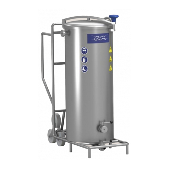
Operating & Maintenance Manual
Cleaning In Place Unit
Model
XX
Valid for
Manufacturing numbers :
Original Manual - English
Alfa Laval Support Services Pvt Ltd
<
:
CIP 200L & 400L
:
CIP 200L & 400L
969951-00, 969951-01, 969951-10,
969951-11, 969952-00, 969952-01
Document No: 130021 R08
Table of
Contents
Previous
Page
Next
Page
1
2
3
4
5
Advertisement
Table of Contents
Need help?
Do you have a question about the CIP 200L and is the answer not in the manual?
Ask a question
Questions and answers
Related Manuals for Alfa Laval CIP 200L
Industrial Equipment Alfa Laval LKDC Instruction Manual
Access tank cover (20 pages)
Industrial Equipment Alfa Laval CPM-2 Instruction Manual
Constant-pressure modulating valve (36 pages)
Industrial Equipment Alfa Laval CB Series Instruction Manual
Brazed plate heat exchangers (26 pages)
Industrial Equipment Alfa Laval AC Series Instruction Manual
Brazed plate heat exchangers (26 pages)
Industrial Equipment Alfa Laval CB Instruction Manual
Brazed and gas-to-liquid plate heat exchangers (33 pages)
Industrial Equipment Alfa Laval AC Instruction Manual
Brazed and gas-to-liquid plate heat exchangers (33 pages)
Industrial Equipment Alfa Laval CIP 400L Original Manual
(38 pages)
Industrial Equipment Alfa Laval CPM-I-D60 Instruction Manual
Constant-pressure modulating inlet valve (40 pages)
Industrial Equipment Alfa Laval COMPABLOC CP15 Installation, Operation And Maintenance Manual
(39 pages)
Industrial Equipment Alfa Laval COMPABLOC CP120 Installation, Operation And Maintenance Manual
(39 pages)
Industrial Equipment Alfa Laval CF100 Installation And Operating Instructions Manual
Separation system (63 pages)
Industrial Equipment Alfa Laval CLARA 80 Operator's Manual
(42 pages)
Industrial Equipment Alfa Laval MBPX404 Installation And Operating Instructions Manual
Separation system (55 pages)
Industrial Equipment Alfa Laval M15 Instruction Manual
Gasketed plate-and-frame heat exchangers (46 pages)
Industrial Equipment Alfa Laval AlfaNova 14 Instruction Manual
Fusion plate heat exchangers (12 pages)
Industrial Equipment Alfa Laval T2 Instruction Manual
Heating insulation for gasketed plate heat exchangers (27 pages)
This manual is also suitable for:
Cip 400l
969951-00
969951-01
969951-10
969951-11
969952-00
...
Show all
969952-01
Table of Contents
Save PDF
Print
Rename the bookmark
Delete bookmark?
Delete from my manuals?
Login
Sign In
OR
Sign in with Facebook
Sign in with Google
Upload manual
Upload from disk
Upload from URL


Need help?
Do you have a question about the CIP 200L and is the answer not in the manual?
Questions and answers