Sign In
Upload
Download
Table of Contents
Contents
Add to my manuals
Delete from my manuals
Share
URL of this page:
HTML Link:
Bookmark this page
Add
Manual will be automatically added to "My Manuals"
Print this page
×
Bookmark added
×
Added to my manuals
Manuals
Brands
Alfa Laval Manuals
Industrial Equipment
T35
Instruction manual
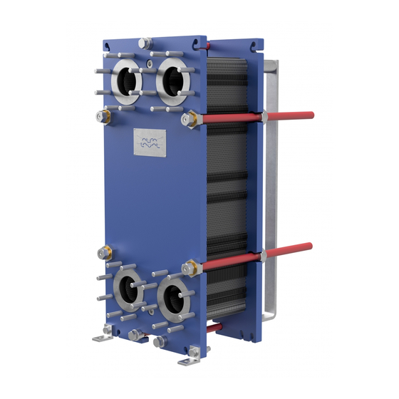
Alfa Laval T35 Instruction Manual
Industrial line, gasketed plate-and-frame heat exchangers
Hide thumbs
1
2
3
4
Table Of Contents
5
6
7
8
9
10
11
12
13
14
15
16
17
18
19
20
21
22
23
24
25
26
27
28
29
30
31
32
33
34
35
36
37
38
39
40
41
42
43
44
45
46
47
48
page
of
48
Go
/
48
Contents
Table of Contents
Bookmarks
Table of Contents
Table of Contents
1 Preface
Conditions and Requirements
Environmental Compliance
2 Safety
Safety Considerations
Definitions of Expressions
3 Description
Components
Name Plate
Function
Multi-Pass
Identification of Plate Side
4 Installation
Before Installation
Requirements
Securing the Heat Exchanger before Lifting
Lifting
Raising
5 Operation
Start-Up
Unit in Operation
Shut-Down
6 Maintenance
Cleaning - Non-Product Side
Opening
Bolt Configuration
Opening Procedure
Manual Cleaning of Opened Units
Deposits Removable with Water and Brush
Removal, Lifting and Insertion of Plates in the Field
Deposits Not Removable with Water and Brush
Closing
Pressure Test after Maintenance
Regasketing
Clip-On / Clipgrip
Base-Ad Gaskets
Glued Gaskets
7 Storage of the Heat Exchanger
Storage in Packing Box
Taken out of Service
Advertisement
Quick Links
1
Conditions and Requirements
2
Components
3
Description
4
Name Plate
5
Requirements
6
Maintenance
Download this manual
Gasketed plate-and-frame heat exchangers
Industrial line - T35, TS35, TL35, T45, T50, TS50, WideGap 350
Instruction Manual
Lit. Code 200000421-1-EN-GB
Table of
Contents
Previous
Page
Next
Page
1
2
3
4
5
Advertisement
Table of Contents
Need help?
Do you have a question about the T35 and is the answer not in the manual?
Ask a question
Questions and answers
Related Manuals for Alfa Laval T35
Industrial Equipment Alfa Laval M15 Manual
(19 pages)
Industrial Equipment Alfa Laval Toftejorg TJ20G Instruction Manual
Rotary jet head (48 pages)
Industrial Equipment Alfa Laval BaseLine M Instruction Manual
Gasketed plate-and-frame heat exchangers (46 pages)
Industrial Equipment Alfa Laval T2 Instruction Manual
Heating insulation for gasketed plate heat exchangers (27 pages)
Industrial Equipment Alfa Laval M3 Manual
(15 pages)
Industrial Equipment Alfa Laval FrontLine WideGap 100 Instruction Manual
Plate heat exchangers (30 pages)
Industrial Equipment Alfa Laval T6 Instruction Manual
Cooling insulation for gasketed plate heat exchangers (26 pages)
Industrial Equipment Alfa Laval Toftejorg TZ-79 Instruction Manual
Covering standard machines, machines delivered with atex certification in accordance with directive 94/9/ec (48 pages)
Industrial Equipment Alfa Laval Toftejorg TZ-67 Instruction Manual
(46 pages)
Industrial Equipment Alfa Laval RODEM Toftejorg TZ-74 Instruction Manual
Brew kettle (47 pages)
Industrial Equipment Alfa Laval M15 Instruction Manual
Gasketed plate-and-frame heat exchangers (46 pages)
Industrial Equipment Alfa Laval M15 Instruction Manual
Plate heat exchangers (21 pages)
Industrial Equipment Alfa Laval TE75P231 Manual
(55 pages)
Industrial Equipment Alfa Laval T6-BZM Instruction Manual
Gasketed plate-and-frame heat exchangers (40 pages)
Industrial Equipment Alfa Laval T6 BZM Instruction Manual
Gasketed plate heat exchangers (62 pages)
Industrial Equipment Alfa Laval TJ40G Instruction Manual
Rotary jet head (52 pages)
This manual is also suitable for:
Ts35
Tl35
T45
Ts50
Widegap 350
T50
Table of Contents
Print
Rename the bookmark
Delete bookmark?
Delete from my manuals?
Login
Sign In
OR
Sign in with Facebook
Sign in with Google
Upload manual
Upload from disk
Upload from URL


Need help?
Do you have a question about the T35 and is the answer not in the manual?
Questions and answers